8 basic DIY regulator circuits. Top 6 brands of regulators from China. 2 schemes. 4 Most asked questions about voltage regulators.+ TEST for self-test
A voltage regulator is a specialized electrical device designed to smoothly change or adjust the voltage supplying an electrical device.
Voltage regulator
Important to remember! Devices of this type are designed to change and adjust the supply voltage, not the current. The current is regulated by the payload!
TEST:
4 questions on the topic of voltage regulators
- Why do you need a regulator:
a) Change in voltage at the output of the device.
b) Breaking the electric current circuit
- What does the regulator power depend on:
a) From the input current source and from the actuator
b) From the size of the consumer
- The main parts of the device, which you can assemble yourself:
a) Zener diode and diode
b) Triac and thyristor
- What are 0-5 volt regulators for?
a) Supply the microcircuit with a stabilized voltage
b) Limit the current consumption of electric lamps
Answers.
a, a, b, a.
How to avoid 3 common mistakes when working with a triac.
- The letter after the triac code indicates its maximum operating voltage: A – 100V, B – 200V, C – 300V, D – 400V. Therefore, you should not take a device with the letters A and B to adjust 0-220 volts - such a triac will fail.
- A triac, like any other semiconductor device, gets very hot during operation; you should consider installing a radiator or an active cooling system.
- When using a triac in load circuits with high current consumption, it is necessary to clearly select the device for the stated purpose. For example, a chandelier with 5 bulbs of 100 watts each will consume a total current of 2 amperes. When choosing from the catalog, you need to look at the maximum operating current of the device. Thus, the MAS97A6 triac is designed for only 0.4 amperes and will not withstand such a load, while the MAS228A8 is capable of passing up to 8 A and is suitable for this load.
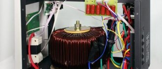
Principle of operation
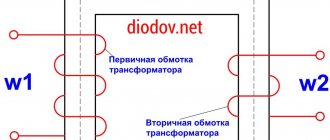
Booster transformers have one winding connected in series with the line in which the voltage is regulated. This winding is powered from a control (supply) transformer, and the primary winding of the latter is supplied from the network or an external current source. Depending on the connection diagram of the windings, booster transformers can create an additional EMF that is phase-shifted relative to the main voltage or coincides with it. In Fig. Figure 2 shows a schematic diagram of connecting a booster transformer.
Figure 2 – Schematic diagram of connecting a booster transformer
- main transformer
- series transformer
- control transformer
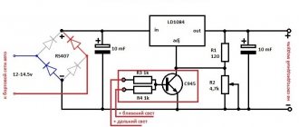
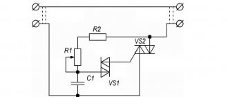
RN on 2 transistors
This type is used in circuits of particularly powerful regulators. In this case, the current to the load is also transmitted through a triac, but the key terminal is controlled through a cascade of transistors. This is implemented like this: a variable resistor regulates the current that goes to the base of the first low-power transistor, which, through the collector-emitter junction, controls the base of the second high-power transistor and it opens and closes the triac. This implements the principle of very smooth control of huge load currents.
SNiP 3.05.06-85
Answers to the 4 most frequently asked questions regarding regulators:
- What is the permissible deviation of the output voltage? For factory instruments of large companies, the deviation will not exceed + -5%
- What does the regulator power depend on? The output power directly depends on the power source and on the triac that switches the circuit.
- What are 0-5 volt regulators for? These devices are most often used to power microcircuits and various circuit boards.
- Why do you need a 0-220 volt household regulator? They are used for smooth switching on and off of household electrical appliances.
Overcurrent and reverse current limiters
When filling a heavily discharged battery or turning on all consumers of the car at the same time, the excitation winding or armature may be destroyed. In the usual case, the current does not exceed 18 - 20 A, which at a voltage of 12 V is equivalent to a power of just over 200 W. The protection circuit is carried out according to an electromechanical pattern. This is a spring-loaded relay, at the moment the current exceeds the maximum threshold, it transfers contacts, drawing in the core with the magnetic field of inductance.
A resistor is included in the excitation winding circuit, extinguishing part of the potential difference across its resistance. This causes a decrease in current. Then the consumption naturally decreases, the contacts close again. The relay works similarly to the previous one, but is configured differently and functions less frequently.
Homemade device
Such protection can fail in the event of a short circuit or a sharp increase in speed. The electronic circuit of current limiters is eliminated from these disadvantages.
The reverse current relay blocks the discharge of the battery through the generator windings. Disconnects the battery when the generator voltage is too low (11.8 - 13 V). As long as the generator is running, current flows through the parallel winding. When the voltage exceeds the threshold, the battery is connected to charge. The relay is cleverly designed and contains two windings:
- The serial one is connected in the circuit between the generator and the wiring branch to the battery.
- The parallel winding is connected after the tap, but before the load.
As a result, when the generator is turned on, the battery is separated from it by an open contact. As the current flowing through both windings increases, the field of the coils increases. When the threshold value is reached, the relay closes and battery charging begins. If the voltage drops, the battery is discharged. Moreover, in the series winding the current is now directed towards the generator (there the potential is lower), and in the parallel winding it flows in the same direction. As a result, half the force is not able to hold the core, and it breaks the connection with the generator. The on-board power supply comes from batteries.
As momentum gains, the situation repeats itself again. At some point, the generator potential exceeds the battery voltage, and the network begins to be powered from here. The full forward load current flows through both windings, the contacts are closed, and the battery is charged. And so on. In addition to the above disadvantages inherent in electromechanical relays, the regulator is affected by the variability of the battery voltage. The voltage drops sharply when the starter is started for obvious reasons.
A negative effect is observed when driving around the city. Opening the relay requires a current of 6 A, which is one third of the total cost. As a result of frequent operation, the battery discharges extremely quickly. This reduces battery life.
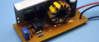
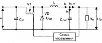
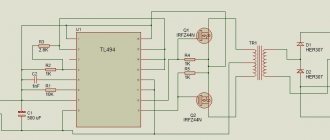
SHI stabilizer
Pulse-width stabilizers are characterized by more stable operation, that is, an almost constant voltage is supplied to the vehicle network, and small deviations within the normal range are smooth. The device circuit uses the same parts as in the original, but at the same time the K561TL1 microcircuit is included. This made it possible to assemble a multivibrator and a short pulse shaper on the 1st node. The output switch control unit has also been simplified due to the use of a field-effect transistor with increased power.
Stabilizer operation cycle
When the ignition is turned on, a low logic level appears at the output of trigger DD1.1. As a result, transistor VT1 opens with the charging current of the capacitor SZ. It, in turn, begins to supply a high level to the inputs of element DD1.2, simultaneously discharging capacitor C4. When a low level appears at the output, DD1.2 opens the field-effect transistor VT3. The current from the stabilizer output flows through the excitation winding of the generator.
After the pulse stops, a high level is formed at the output of DD1.1 and transistor VT1 closes. Capacitor C4 is charged by the current passing through resistor R5 from the generator, which is controlled by transistor VT2. While the voltage on capacitor C4 drops to the lower switching limit of trigger DD1.2, it will switch. A high level will appear at its output, which will close transistor VT3. In order to protect the input circuits of the DD1 microcircuit, the voltage of capacitor C4 is limited by the diode VD4, which, when it is subsequently charged, will not lead to switching DD1.2. When a low-level pulse is again formed at the output of the generator, the process begins to repeat.
Thus, stabilization is carried out by the duration of the on state of the field-effect transistor, and the process is controlled by a measuring device, as well as a current generator. When the voltage at the generator output increases, the collector current of transistor VT2 increases. As the amperage increases, capacitor C4 begins to charge faster and the duration of the on state of transistor VT3 decreases. As a result, the current that flows through the excitation winding of the generator decreases and, of course, the output voltage of the generator decreases.
When the voltage at the output from the generator decreases, the current at the collector of transistor VT2 decreases. As a result, the charging time of capacitor C4 increases. This leads to a longer period of switching on of the transistor VT3 and the current that flows through the excitation winding of the generator increases. The generator output voltage also increases.
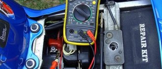
Checking an Individual Regulator
Checking the voltage regulator of the G-222 generator: 1 - battery; 2 - voltage regulator; 3 - control lamp.
As a rule, separate voltage regulators were installed on old cars, including domestic VAZs. But some manufacturers continue to do this to this day. The verification process is similar. To do this, you need to have a power supply with a voltage regulator, a 12 V light bulb, a multimeter and a directly tested regulator.
To check, you need to assemble the circuit shown in the figure. The process itself is similar to the one above. In normal condition (at a voltage of 12 V), the light bulb lights up. When the voltage value increases to 14.5 V, it goes out, and when it decreases, it lights up again. If during the process the lamp lights up or goes out at other values, it means that the regulator has failed.
This is interesting: How to replace valve guides
Checking relay type 591.3702-01
Relay test diagram type 591.3702-01
You can also still find a voltage regulator of type 591.3702-01, which was installed on rear-wheel drive VAZs (from VAZ 2101 to VAZ 2107), GAZ and Moskvich. The device is mounted separately and installed on the body. In general, the test is similar to that described above, but the differences are in the contacts used.
In particular, it has two main contacts - “67” and “15”. The first of them is a minus, and the second is a plus. Accordingly, to check it is necessary to assemble the circuit shown in the figure. The verification principle remains the same. In normal condition, at a voltage of 12 V, the light bulb lights up, and when the corresponding value increases to 14.5 V, it goes out. When the value returns to its original value, the light comes on again.
A classic regulator of this type is a device of the PP-380 brand, installed on VAZ 2101 and VAZ 2102 cars. We provide reference data regarding this regulator.
| Adjustable voltage at regulator and ambient temperature (50±3)° C, V: | |
| at the first stage | no more than 0.7 |
| on the second stage | 14,2 ± 0,3 |
| Resistance between plug “15” and ground, Ohm | 17,7 ± 2 |
| Resistance between plug “15” and plug “67” with open contacts, Ohm | 5,65 ± 0,3 |
| Air gap between armature and core, mm | 1,4 ± 0,07 |
| Distance between second stage contacts, mm | 0,45 ± 0,1 |
Testing a three-level relay
Regulated power supply
Some car owners install on their cars, instead of standard “chocolate bars,” three-level relays, which are technologically more advanced. Their difference is the presence of three voltage levels at which the battery power is cut off (for example, 13.7 V, 14.2 V and 14.7 V). The appropriate level can be set manually using a special regulator.
Such relays are more reliable and allow flexible adjustment of the cutoff voltage level. As for checking such a regulator, it is completely similar to the procedures described above. Just do not forget about the value that is set on the relay, and accordingly, check it with a multimeter.
Generator check
There is one method by which you can check the performance of a car generator equipped with a regulator relay 591.3702-01 with diagnostic elements. It is as follows:
- disconnect the wires that went to pins 67 and 15 of the voltage regulator;
- connect a light bulb to it (excluding the regulator from the circuit);
- Remove the wire from the positive terminal of the battery.
If, as a result of these actions, the engine does not stall, then we can say that the car’s generator is in order. Otherwise, it is faulty and needs to be checked and replaced.
Scheme and design
A more detailed diagram of a linear regulator, also illustrating the principle of switching contacts, is presented in Fig. 3. It shows the control transformer 1 and the series transformer 2. The primary winding 3 of the control transformer is the supply winding. It can be connected to both phase A - 0 and line voltage (A - B, A - C). The secondary winding 4 of the control transformer has the same switching device 5 as the transformer with on-load tap-changer.
One end of the primary winding 6 of the series transformer is connected to the midpoint of the secondary winding of the control transformer. The other is to the switching device. The secondary winding 7 of the series transformer is connected in series with the winding of the power transformer. The additional EMF in winding 7 adds up to the EMF of the power transformer and changes it.
Figure 3 – Operating principle of a booster transformer
In Fig. Figure 4 shows a three-phase circuit for connecting a booster transformer to the network.
Figure 4 – Scheme for connecting a voltage booster transformer to the network
Linear regulators operate according to an autotransformer circuit and are an oil-filled design that has six linear terminals for connecting the regulator to a line cut at any point. The connection diagram of the linear regulator is shown in Fig. 5.
- High voltage field winding
- Control circuit power winding
- Voltage booster winding
- Moving switch contact
- Auxiliary switch contact with active current-limiting resistance
- Fixed contacts
Figure 5 – Linear regulator connection diagram
The simplest way to check the generator voltage regulator
The simplest method of checking the regulator is to measure the voltage at the battery terminals with a multimeter. However, it is worth immediately making a reservation that the algorithm given below does not give a 100% probability of failure of the regulator. Perhaps the generator itself has failed. But the advantage of this method is that it is simple and there is no need to dismantle the device from the car. So, the algorithm for checking the generator voltage regulator with a multimeter is as follows:
- Set the tester to DC voltage measurement mode at a limit of about 20 V (depending on the specific model, the main thing is that it displays values up to 20 V as accurately as possible).
- Start the engine.
- Measure the voltage at the battery terminals in idle mode (1000...1500 rpm). If the regulator and generator are working properly, the value should be within 13.2…14 V.
- Increase speed to 2000…2500 rpm. In the normal state of the electrical circuit, the corresponding voltage will increase to 13.6 ... 14.2 V.
- When the speed increases to 3500 rpm and above, the voltage should not exceed 14.5 V.
If during the test the voltage values are very different from those given, then most likely the machine’s voltage regulator is faulty. Remember that the voltage should not fall below 12V and should not rise above 14.5V.
As mentioned above, the regulator can be separate or combined with a generator. Currently, almost all foreign cars, and most modern domestic cars, have combined relays installed. This is due to the specifics of their work and space saving.
Types of regulator relays
Before you independently repair the voltage regulation device, you must take into account that there are several types of regulators:
- external – increase the maintainability of the generator
- built-in – in the rectifier plate or brush assembly
- regulating by minus - an additional wire appears
- positive regulating – economical connection scheme
- for alternating current generators - there is no function for limiting the voltage on the excitation winding, since it is built into the generator itself
- for DC generators – an additional option for cutting off the battery when the internal combustion engine is not working
- two-level - obsolete, rarely used, adjustment by springs and a small lever
- three-level – supplemented with a special comparison device board and a matching indicator
- multi-level - the circuit has 3 - 5 additional resistors and a tracking system
- transistor - not used in modern cars
- relay – improved feedback
- relay-transistor - universal circuit
- microprocessor - small dimensions, smooth adjustment of the lower/upper threshold of operation
- integral - built into brush holders, therefore they are replaced after the brushes wear out
Attention: Without modification of the circuit, the “plus” and “minus” voltage regulators are not interchangeable devices.
DC generator relay
Thus, the connection diagram for the voltage regulator when operating a DC generator is more complicated. Since in the parking mode of the car, when the internal combustion engine is turned off, it is necessary to disconnect the generator from the battery.
During diagnostics, the relay is checked to perform its three functions:
- Battery cut off when the car is parked
- limiting the maximum current at the generator output
- voltage adjustment for field winding
Any malfunction requires repair.
Alternator relay
Unlike the previous case, diagnosing the alternator regulator yourself is a little simpler. The design of the “automotive power station” already includes the function of cutting off power from the battery while parked. All that remains is to check the voltage at the excitation winding and at the output from the generator.
If the car has an alternating current generator, it is impossible to start it by accelerating down a hill. Since there is no residual magnetization on the exciting winding here by default.
Built-in and external regulators
It is important for a car enthusiast to know that they measure and begin to regulate the relay voltage at a specific location where they are installed. Therefore, built-in modifications act directly on the generator, while external modifications “do not know” about its presence in the machine.
For example, if a remote relay is connected to the ignition coil, its work will be aimed at regulating the voltage only in this section of the on-board network. Therefore, before you learn how to test a remote-type relay, you should make sure that it is connected correctly.
Control by “+” and “–”
In principle, the control circuits for “minus” and “plus” differ only in the connection diagram:
- when installing the relay in the “+” gap, one brush is connected to “ground”, the other to the regulator terminal
- if you connect the relay to the “–” gap, then one brush needs to be connected to the “plus”, the other to the regulator
However, in the latter case, another wire will appear, since the voltage relay is an active type device. It requires individual nutrition, so “+” must be supplied separately.
Two-level
At the initial stage, mechanical two-level voltage regulators with a simple operating principle were installed in the machines:
- Electric current passes through the relay
- the resulting magnetic field attracts the lever
- the comparison device is a spring with a given force
- When the voltage increases, the contacts open
- less current flows to the exciting winding
Mechanical two-level relays were used in VAZ 21099 cars. The main disadvantage was working with increased wear of mechanical elements. Therefore, these devices have been replaced by electronic (contactless) voltage relays:
- voltage divider made of resistors
- The zener diode is the master device
Complex wiring and insufficient voltage control have led to a decrease in demand for these devices.
Three-level
However, two-level regulators, in turn, also gave way to more advanced three-level and multi-level devices:
- the voltage goes from the generator to a special circuit through a divider
- the information is processed, the actual voltage is compared with the minimum and maximum threshold values
- the mismatch signal regulates the current flowing to the exciting winding
Relays with frequency modulation are considered more advanced - they do not have the usual resistances, but the frequency of operation of the electronic key is increased. Control is carried out by logical circuits.