Types of stabilizers
Stabilizers may differ in:
- output power;
- by number of phases;
- by the method of converting and stabilizing the potential difference;
- at a cost that directly depends on the first three points.
There are four types of stabilizers:
Relay is the most inexpensive. Modes are switched using relays that are activated by the electronic control unit. A significant drawback of such devices is their noise, because the relay mechanically disconnects the contact that is connected to one or another winding of the transformer. Switching operating modes is also not instantaneous, so equalization of the potential difference occurs with some delay.
Electromechanical - capable of smoothly regulating the voltage in the network, but the performance of such a device cannot but upset those who experience sudden changes in the network. The principle of operation is that the electronic control unit analyzes the voltage in the network and, if there is a significant deviation, gives a command to move a special slider that moves along the transformer. With this stabilization method, the degree of voltage transformation is regulated by turning on more turns of the transformer. To protect electrical equipment that is connected to the stabilizer from an excessively high potential difference, to which this device will not have time to respond properly. A relay is installed in the electrical circuit of this device, which stops the supply of electric current in the event of such a critical situation.
Read also: Sharpening angles for wood saw blades
Ferroresonant - used extremely rarely due to low efficiency, high noise level, large dimensions and high price. The advantage of such stabilizers lies only in their high durability and reliability.
Electronic is the most expensive device for stabilizing the voltage in the network. The high cost of such equipment is due to the use of thyristors and semistors in its design as keys. Electronic stabilizers switch operating modes almost instantly, which is an important characteristic of such electronic devices, because a voltage surge will not have time to cause damage to the protected equipment. Thyristor potential difference stabilizers have the longest service life, and despite the high cost of such products, the installation of such devices is more economical and justified due to the advantages that these electrical devices have over similar devices.
Operating principle of ferroresonance stabilizers
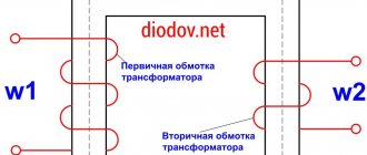
The primary winding, which receives the input voltage, is located on the magnetic core. It has a large cross-section, which allows the core to be kept in an unsaturated state. At the input voltage forms magnetic fluxes.
The output voltage is generated at the terminals of the secondary winding. A load is connected to this winding, which is located on the core, has a small cross-section and is in a saturated state. In case of anomalies in the mains voltage and magnetic flux, its value is not actually modified, and the EMF indicator also remains unchanged. During an increase in the magnetic flux, some of it will be closed on the magnetic shunt.
The magnetic flux takes on a sinusoidal shape and, as it approaches the amplitude indicator, a separate section of it goes into saturation mode. The increase in magnetic flux stops. The flow through the magnetic shunt will be closed only when the magnetic flux is equal to the amplitude.
The presence of a capacitor allows the ferroresonant stabilizer to operate with an increased power coefficient. The stabilization indicator depends on the level of slope of the horizontal curve with respect to the abscissa. The slope of this area is significant, so it is impossible to achieve a high level of stabilization without auxiliary equipment.
Stabilizer selection
To select a 220 volt stabilizer for your home, first of all, you should decide under what conditions this device will be used.
To make the right choice, you need to accurately determine the following parameters:
- The type of device used also depends on how many phases are connected to the home electrical network. With a three-phase power supply, the device selected, as a rule, is of high power, sufficient to power all electrical appliances in the house. In fact, a three-phase transformer consists of three single-phase voltage stabilization circuits, which necessarily have built-in protection against phase loss. As a result, the price of this device is at least three times higher than the cost of a high-quality single-phase stabilizer. If single-phase voltage is supplied to the house, then a conventional transformer for single-phase networks is selected. This device can be installed both on the electrical panel and directly in front of those electrical devices that require stabilization of the potential difference.
- The choice of stabilizer depends on the total power consumption of the devices connected to it. If the voltage stabilizer will be used only with devices that convert electrical energy into heat, then in this case it is enough to calculate the total power of the connected devices, plus a margin of 20%. If the device is used to normalize the voltage for the operation of household appliances, which, when turned on, consume significantly more current than during their standard operation, then it is necessary to purchase devices with increased power that can provide energy consumers with the necessary reserve of starting current. For example, a refrigerator with a power of 300 W consumes at least 1200 W when the compressor is turned on; this fact should be taken into account when calculating the power of the purchased device to normalize the electric current.
- If it is necessary to install a stabilizer in a residential area, the noise level generated by switching operating modes and vibration of the coils will negatively affect the well-being of people in the immediate vicinity of the device. Today, electronic models are the quietest, and when a device with exactly these characteristics is required, there is no alternative to them.
- If the device for normalizing voltage is planned to be installed in a room with very limited free space , for example, in the kitchen, then preference in the choice should be given to models that have a minimum size.
There are “mini” class models, they are ideal for installation in such places, but the power of these devices is not enough to power powerful electricity consumers, as well as energy consumers with a very high starting current.
Installation and connection
Two connection options are possible:
- Installing the device at the entrance of the electrical network to the house, thus normalizing the potential difference of absolutely all electricity consumers connected to the home electrical network. Such installation, as a rule, is carried out only by powerful single-phase or three-phase devices.
- Connection to only one consumer or group of electrical devices. In this case, it is enough to connect the stabilizer to an outlet, and connect the plug from the household appliance to the output of the stabilizer. The device can be mounted either on the floor or on a wall, it all depends on the specific operating conditions and the availability of free space for one or another installation method.
How to make transformers T1 and T2?
The first transformer T1 with a power of 3 kW is manufactured using a magnetic core with a cross-sectional area (CSA) of 187 sq. mm. And three wires PEV-2:
- For the first wrapping, the PPS is only 0.003 square meters. mm. Number of turns – 8669;
- For the second and third windings, the PPS is only 0.027 sq. mm. The number of turns is 522 on each.
If you don’t want to wind the wire, then you can purchase two TPK-2-2×12V transformers and connect them in series, as in the figure below.
To make an autotransformer with a second power of 6 kW, you will need a toroidal magnetic core and PEV-2 wire, from which a wrap of 455 turns will be made. And here we need bends (7 pieces):
- Wrapping 1-3 bends from wire with PPS 7 sq. mm;
- Wrapping 4-7 bends from wire with PPS 254 sq. mm.
Taps are made on turns (counting from bottom to top): 203, 232, 266, 305, 348, 398. From the network, voltage should be supplied to turn No. 266.
Operating rules
- A stabilizer is a device whose efficiency is not 100%, so during its operation heat is generated, which must be removed from the device body. For this purpose, there are holes of various sizes on the surface of the stabilizer to utilize thermal energy. It is strictly forbidden to cover operating devices with materials that impede the free circulation of air through these openings.
- The device should not be installed in places where water may enter the device housing.
- The stabilizer must be connected only to the load for which this device is designed. Otherwise, overheating and premature failure of the device is possible.
The electrical network in many of our homes cannot boast of high quality, this is especially true for rural areas that are far from the city. Therefore, voltage surges often occur. Local manufacturers of electrical appliances take this circumstance into account and provide a safety margin. But many people mainly use foreign technology, for which such jumps are destructive. Therefore, it is necessary to use special devices. And you don’t have to buy them in stores; you can make a 220V voltage stabilizer with your own hands according to the diagram. This task is not entirely difficult if you do everything according to the instructions.
Just before assembly, you need to familiarize yourself with the existing types of such devices and find out what their operating principle is.
Operating conditions of the device
During the current conversion process, it is necessary to protect the device from moisture, dust, overheating and mechanical damage. The device cannot be put into operation if condensation has formed in the housing due to a change in ambient temperature ; to protect the stabilizer from a short circuit, it is necessary to wait until the moisture has completely evaporated from the internal elements of the equipment.
A self-made current rectifier made in a private workshop can only be used in dry rooms where there are no rodents, insects, explosive or flammable materials. To stabilize the frequency of current fluctuations, the device must be installed in an open space, at a distance of at least 50 mm from the wall, and a neutral or phase cable must be used.
- Author: admin
Rate this article:
- 5
- 4
- 3
- 2
- 1
(1 vote, average: 1 out of 5)
Share with your friends!
Necessary measure
Ideally, the electrical network can operate efficiently with minor voltage drops - no more than 10%, both higher and lower than the nominal 220V. However, as real operating conditions show, these changes are sometimes quite significant. And this already threatens the failure of connected devices.
And to avoid such troubles, a device such as a voltage stabilizer was created. And if the current goes beyond the permissible value, the device will automatically de-energize the connected electrical appliances.
What else could cause the need for such a device and why do some people think about making a homemade 220V voltage stabilizer according to the circuit? The presence of such an assistant is justified due to the following possibilities:
- Household appliances are guaranteed to work for a long time.
- Mains voltage monitoring.
- The specified voltage level is maintained automatically.
- Current surges do not affect electrical appliances.
If such electrical “anomalies” happen frequently where you live, you should think about purchasing a good stabilizer. As a last resort, assemble it yourself.
Read also: Heating time of polypropylene pipes during soldering table
Characteristics of the current stabilizer
A household electric current rectifier, which you can assemble yourself in a private workshop, equalizes the current provided a current of 130-270 V is supplied. The device does not respond to the oscillation frequency of electricity coming from the central power line. Electrical appliances with a total power of up to 6 kW can be connected to the device.
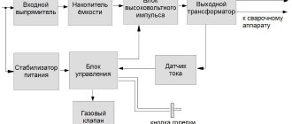
The electronic voltage equalizer automatically switches loads within 10 ms. The principle of operation of the device is to carry out two processes:
- Converting alternating mains current into consumer direct current.
- Conversion of consumer direct current into network alternating current.
Types of stabilizers
The main component of any such protective electrical device is its adjustable autotransformer. Currently, many manufacturers produce several types of devices that have their own voltage stabilization technology. These include two main 220V voltage stabilizer circuits for the home:
There are also ferroresonant analogues, which are practically not used in everyday life, but they will be discussed a little later. Now it’s worth moving on to a description of existing models.
Manufacturing of power transformer
The power supply transformer T1, as mentioned above, is one of the main elements of the voltage stabilizer, so its manufacture should be taken responsibly. But making it yourself is very problematic.
Therefore, for greater simplicity, you can purchase 2 finished products of the TPK-2-2 brand. The output voltage of each converter is 12 V, to obtain 24 V, the transformers must be connected in series. The connection diagram is shown below (Figure 3).
Unfortunately, the T2 transformer cannot be purchased, but only made independently. To do this you will need:
- toroidal magnetic core (which can be used as a 10 kW motor stator);
- PEV-2 wire with a diameter of at least 4.2 mm.
The conclusions of the autotransformer, starting from the bottom, are made from: 150, 164, 180, 196, 218 and 246 turns.
Electromechanical (servo-drive) devices
The mains voltage is adjusted using a slider that moves along the winding. At the same time, different numbers of turns are used. We all studied at school, and some of us may have dealt with a rheostat in physics lessons.
An electromechanical voltage stabilizer works on this similar principle. Only the slider is moved not manually, but using an electric motor called a servo drive. It is simply necessary to know the structure of these devices if you want to make a 220V voltage stabilizer with your own hands according to the diagram.
Electromechanical devices are highly reliable and provide smooth voltage regulation. Characteristic advantages:
- Stabilizers work under any load.
- The resource is significantly greater than that of other analogues.
- Affordable cost (half lower than electronic devices)
Unfortunately, with all the advantages there are also disadvantages:
- Due to the mechanical design, the response delay is very noticeable.
- Such devices use carbon contacts, which are subject to natural wear and tear over time.
- The presence of noise during operation, although it is practically inaudible.
- Small operating range 140-260 V.
It is worth noting that, unlike the 220V inverter voltage stabilizer (you can make it with your own hands according to the circuit, despite the apparent difficulties), there is also a transformer. As for the operating principle, voltage analysis is performed by an electronic control unit. If it notices significant deviations from the nominal value, it sends a command to move the slider.
The current is adjusted by connecting more turns of the transformer. In case the device does not have time to react in a timely manner to excessive voltage, a relay is provided in the stabilizer device.
Electronic stabilizers
The operating principle of electronic devices is a little different. There are several schemes underlying this:
- thyristor or seven-storage;
- relay;
- inverter
Such devices operate silently, with the exception of relay stabilizers. They switch modes using power relays controlled by an electronic control unit. Since they mechanically disconnect the contacts, noise can be heard from time to time during operation of such devices. For some, this may be a serious disadvantage.
Therefore, the best choice would be to purchase or make a 220V inverter voltage stabilizer with your own hands, the circuit diagram of which is not difficult to find.
Other electronic analogues have special switches, thyristors and semistors, and therefore they operate in silent mode. This also allows the stabilizers to operate almost instantly. Other advantages include:
- no heating;
- the operating range is 85-305 V (for relay devices it is 100-280 V);
- compact dimensions;
- low cost (again applicable to relay stabilizers).
A common disadvantage of electronic devices is the step-by-step circuit for regulating the mains voltage. In addition, thyristor devices have the highest cost, but at the same time they have a very long service life.
Electronic voltage stabilizer circuit
Choosing a voltage stabilizer for your home
Let's take a closer look at how to make an electronic voltage stabilizer with your own hands for 220V, assembling the circuit and setting it up. The circuit of such a stabilizer is simple and in demand among consumers, time-tested.
Main technical characteristics:
- Network input voltage range – 160-250V;
- The output voltage after stabilization is 220V;
- The permissible power consumed by the load is 2 kW;
This power is quite enough to connect one or more valuable household appliances that are sensitive to voltage surges through the stabilizer. The weight and dimensions of the device depend on the case; the main elements, transformer and board can be placed in a ready-made box or case from other electrical equipment.
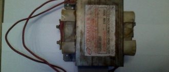
Practice shows that a homemade voltage stabilizer has some difficulties during assembly: one of the labor-intensive processes in assembling a stabilizer circuit is the manufacture of a transformer, but in our case this work can be simplified. For this circuit, transformers of the TS180-TS320 brand are ideal for a 220V voltage stabilizer; they may not be available in retail chains, but you can buy them on old TVs and in markets for 300-500 rubles.
Appearance of transformer TS-180
Transformers of the TN and TPP series also showed their performance well as part of this circuit. The secondary windings of these transformers produce voltages from 24 to 36 volts and can withstand load currents of up to 8A.
Basic elements and operating principle of the circuit
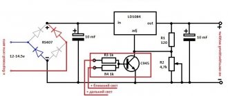
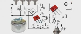
A mains voltage of 160-250V is supplied to the primary winding of the transformer; after transformation, a voltage of 24-36V is supplied from the output of the secondary winding to the diode bridge VD1. The key transistor VT1 is connected to the circuit through a voltage stabilizer DA1 with a variable resistance R5, which regulates the voltage at the output of the stabilizer. Parallel stabilizer DA1 and diode bridge VD2 monitor the error voltage and amplify it.
Electrical circuit diagram of the electronic stabilizer
As the network voltage increases, the voltage of the secondary winding also increases on capacitor C3, which leads to the opening of the zener diode DA1, thus shunting the voltage across resistor R7. This leads to a voltage drop at the gate of transistor VT1, it closes, and at the output contacts of the stabilized voltage XT3, XT4 its increase is limited.
When the voltage on the primary winding is reduced, a reverse reaction occurs: the voltage on the secondary winding decreases, the zener diode DA1 closes, the transistor opens, and the voltage on the secondary winding increases.
The HL1 LED shows the state of the key transistor; when it is open, additional voltage is applied to the secondary winding, and the diode lights up. Zener diode VD3 limits the voltage to the set value, protecting the transistor gate from overvoltage.
The transistor is installed on a 50x50x10 mm duralumin radiator, usually this is enough to remove heat; the power line wires must have a cross-section of at least 4 mm2, the wires in the control circuits must have a smaller cross-section.
An example of installing a transistor on a radiator
It is advisable to install fuses FU1, FU2 at 8-10 A.
Characteristics of circuit elements
| the name of detail | Brand | Nominal value | Quantity |
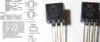
| DA1 | Voltage reference source | TL431 | * |
| VT1 | MOSFET transistor | IRF840 | * |
| VD1 | Diode bridge | RS805 | * |
| VD2 | Rectifying diode | RL102 | **** |
| VD3 | Parallel Zener diode | KS156B | * |
| C1 | Capacitor (capacitance) | 0.1 mkf \400 V | * |
| C2 | Capacitor(electrolyte) | 10 mkf \450 V | * |
| C3 | Electrolytic capacitor | 47 mkf 25 V | * |
| C3 | Capacitor | 1000 pF | * |
| C4 | Capacitor | 0.22 mF | * |
| R1 | Resistance | 5600 Ω | * |
| R2 | Resistance | 2200 Ω | * |
| R3 | Resistance | 1500 Ω | * |
| R4 | Resistance | 8200 Ω | * |
| R5 | Variable resistor | 2200 Ω | * |
| R6 | Resistance | 1000 Ω | * |
| R7 | Resistance | 1200 Ω | * |
| T1 | Transformer | TS320 | * |
| NL1 | Light-emitting diode | AL307B | * |
| FU1, FU2 | Fuse | 10 A | ** |
| SA1 | Switch | * | |
| XT1-XT4 | Grounding Plug | ** |
To install all the elements, a printed circuit board is used, the manufacture of which requires a more detailed consideration in a separate topic. If necessary, you can order the production of a board for this circuit from specialists who do this professionally on the website https://megapcb.com/.
As you can see, the 220V voltage stabilizer circuit is easy to assemble with your own hands and works reliably.
Very important! After assembly, it is necessary to adjust the output voltage stabilization limits. To do this, connect a regular 100-200 W incandescent lamp to the output of the stabilizer, then you need to set the variable resistor R5 at the output to 225V. Then connect a larger load up to 1.5 kV and increase the voltage to 220V. Measurements can be carried out with a conventional multimeter or a pointer voltmeter can be installed in the circuit. After 10 minutes of operation at maximum load, feel how hot the transistor is and, if necessary, increase the size of the radiator.
Important! Do not forget that the transistor is attached to the radiator using heat-conducting paste through a mica gasket. For safety reasons, use a three-wire cord or a cable with a plug that has a ground terminal at the input of the stabilizer. Connect the ground wire to the neutral line on the board and case, especially when it is metal.
Inverter technology
A distinctive feature of such devices is the absence of a transformer in the design of the device. However, voltage regulation is carried out electronically, and therefore it belongs to the previous type, but is, as it were, a separate class.
If you want to make a homemade 220V voltage stabilizer, the circuit of which is not difficult to obtain, then it is better to choose inverter technology. After all, the principle of operation itself is interesting here. Inverter stabilizers are equipped with double filters, which allows minimizing voltage deviations from the nominal value within 0.5%. The current entering the device is converted into direct voltage, passes through the entire device, and before exiting it again takes on its previous form.
Ferroresonance analogues
The operating principle of ferroresonant stabilizers is based on the magnetic resonance effect that occurs in a system with chokes and capacitors. In operation, they are a little similar to electromechanical devices, only instead of a slider there is a ferromagnetic core that moves relative to the coils.
This system is highly reliable, but is large in size and makes a lot of noise during operation. There is also a serious drawback - such devices operate only under load.
If previously such a 220V network voltage stabilizer circuit was popular, now it is better to abandon it. In addition, sinusoidal distortions cannot be excluded here. For this reason, this option is not suitable for modern household electrical appliances. But if the household has powerful electric motors, hand tools, and welding machines, then such stabilizers are still applicable.
Ferroresonance stabilizers were widespread in everyday life 20 or 30 years ago. At that time, old televisions were powered through them, since they had a special design that did not allow safe use of the electrical network directly. There are modern models of these stabilizers that do not have many disadvantages, but they are very expensive.
Homemade apparatus
What kind of 220V voltage stabilizer circuit can you implement with your own hands? The simplest version of the stabilizer consists of a minimum number of components:
- transformer;
- capacitor;
- diodes;
- resistor;
- wires (for connecting microcircuits).
Using simple skills, assembling the device is not as difficult as it might seem. But if you have an old welding machine, everything becomes simpler, since it is practically already assembled. However, the problem is that not every person has such a welding machine, and therefore it is better to find another method for a homemade device.
For this reason, let's look at how you can make some analogue of a triac stabilizer. This device will be designed for an input operating range of 130-270 V, and the output will be supplied from 205 to 230 V. A large difference in the input current is rather a plus, but for the output current it is already a minus. But for many household appliances this difference is acceptable.
As for power, the circuit of a 220V thyristor voltage stabilizer, made by hand, allows the connection of electrical appliances up to 6 kW. The load switches within 10 milliseconds.
How to make transformers T1 and T2?
The first transformer T1 with a power of 3 kW is manufactured using a magnetic core with a cross-sectional area (CSA) of 187 sq. mm. And three wires PEV-2:
- For the first wrapping, the PPS is only 0.003 square meters. mm. Number of turns – 8669;
- For the second and third windings, the PPS is only 0.027 sq. mm. The number of turns is 522 on each.
If you don’t want to wind the wire, then you can purchase two TPK-2-2×12V transformers and connect them in series, as in the figure below.
To make an autotransformer with a second power of 6 kW, you will need a toroidal magnetic core and PEV-2 wire, from which a wrap of 455 turns will be made. And here we need bends (7 pieces):
- Wrapping 1-3 bends from wire with PPS 7 sq. mm;
- Wrapping 4-7 bends from wire with PPS 254 sq. mm.
Taps are made on turns (counting from bottom to top): 203, 232, 266, 305, 348, 398. From the network, voltage should be supplied to turn No. 266.
Advantages of a homemade device
A stabilizer made independently has its pros and cons, which you should definitely know about. Main advantages:
- low cost;
- maintainability;
- independent diagnostics.
Read also: Production of plastic parts
The most obvious advantage is its low cost. All parts will need to be purchased separately, and this is still incomparable with ready-made stabilizers.
If any element of the purchased voltage stabilizer fails, it is unlikely that you can replace it yourself. In this case, all that remains is to call a technician to your home or take him to a service center. Even if you have some knowledge in the field of electrical engineering, finding the right part is not so easy. It’s a completely different matter if the device was made by hand. All the details are already familiar and to buy a new one, just visit the store.
If anyone has previously assembled a 220V 10kW voltage stabilizer circuit with their own hands, it means that the person already understands many of the intricacies. This means that identifying the malfunction will not be difficult.
Disadvantages to Consider
Now let's touch on some of the disadvantages. No matter how much he praises himself, he will not be able to compete with real professionals in the electrical field. For this simple reason, the reliability of a homemade stabilizer will be inferior to branded analogues. This is due to the fact that production uses high-precision instrumentation, which ordinary consumers do not have.
Another point is a wider operating voltage range. If for a store-bought version it ranges from 215 to 220V, then for a device created at home, this parameter will be exceeded 2 or even 5 times. And this is already critical for a large number of modern household appliances.
Features of home production
All elements will be placed on a printed circuit board measuring 115x90 mm. Why can you use foil fiberglass? The layout of all working components can be printed on a laser printer, and then everything can be transferred using an iron. The example itself is below.
Now you can move on to making transformers. And here everything is not so simple. In total you need to make two elements. For the first one you need to take:
- magnetic core with a cross-sectional area of 187 mm 2;
- three PEV-2 wires.
Moreover, one of the wires should be 0.064 mm thick, and the other – 0.185 mm. To begin with, a primary winding is created with the number of turns - 8669. Subsequent windings have fewer turns - 522.
The electrical circuit of the 220V voltage stabilizer provides for the presence of two transformers. Therefore, after assembling the first element, it is worth moving on to manufacturing the second. And for this you already need a toroidal magnetic circuit. The winding here is also made from PEV-2 wire, except that the number of turns will be equal to 455. In addition, seven taps should come from the second transformer. The first three require a wire with a diameter of 3 mm, and the remaining 4 will be made from tires with a cross-section of 18 mm². Thanks to this, the transformer will not heat up while using the stabilizer.
The task can be significantly simplified if you take two ready-made TPK-2-2 12V elements and connect them in series. All other necessary parts must be purchased in the store.
DIY voltage stabilizer
To collect all the necessary elements, you will have to go to the store, but you can try to make some parts yourself.
Manufacturing of transformers
This primarily applies to devices T1 and T2. To produce T1, the power of which should be 3 kW, a magnetic core with a cross-section of 1.87 cm 2 is required, as well as three PEV-2 conductors. The diameter of the “first of the last” should be 0.12 mm (section - 0.064 mm 2). It is used to create the primary winding, the number of turns is 8669. The rest are used for other windings, the diameter of both wires is 0.185 mm. The number of turns is also the same - 552 each.
An alternative is to use a pair of ready-made transformers - TPK-2-2×12V, they are connected in series:
Transformer T2 must have a power of 6 kW. For its manufacture, a toroidal magnetic circuit is used. For the winding they take the same PEV-2, the number of turns in this case is 455. 7 taps are made here. For the first three you need a wire with a diameter of 3 mm. The remaining 4 require tires with a cross section of 18 mm 2. The goal is to prevent the transformer from heating up. Bends are made at 203, 232, 266, 305, 348 and 398, counting from below. The current from the network must pass through the tap at the 266th turn.
What else will you need to buy?
All other items must be purchased in the store. The set includes:
- triac optocouplers MOC3041 - 7 parts;
- triacs BTA41-800B - also seven;
- 2 diodes DF005M (VD1 and VD2) and comparator LM339N (for DA2, DA3);
- stabilizer KR1158EN6A (DA1), fuse switch;
- capacitors: 4 oxide (for C1-3, C-5), the same number of film or ceramic (C4, C6-C8);
- resistors with different tolerance percentages: 7 pieces C2-23 for R16-22 with 1%, 30 any with 5%;
- 3 wirewound resistors for R13-14, R25 - SP5-2 or SP5-3;
- 7 current limiting resistors (16 mA) - for R41-47.
A full replacement is possible: MOC3041 with MOC3061, KR1158EN6A with KR1158EN6B, LM339N with K1401CA1. Suitable diodes would be KTs407A.
The KR1158EN6A stabilizer is mounted on a heat sink. An aluminum plate is used for this purpose. Its area is more than 15 cm2. Triacs are installed on it. All elements can be mounted on one heat sink, but it must have a fairly large cooling surface. Its area is at least 0.16 m2.
You will also need to purchase a KR1554LP5 microcircuit; it will “perform the duties” of a microcontroller. You need to purchase 9 flashing LEDs, but you can also buy regular ones that produce bright red light: for example, AL307KM or L1543SRC-E. There are usually no difficulties with purchasing parts, and spending on them can be considered a reasonable investment that will soon pay off.
Assembly process
Assembling the stabilizer begins with installing the microcircuit on the heat sink. This can be an aluminum plate with an area of at least 15 cm2, on which triacs should also be placed. For the stabilizer to operate effectively, you cannot do without a microcontroller, for which you can use the KR1554LP5 microcircuit.
Of course, this is not a 220V inverter voltage stabilizer circuit, but for domestic needs such a device is quite sufficient. At the next stage, you need to arrange the LEDs, and you need to take the blinking ones. However, you can use others, for example, AL307KM or L1543SRC-E, which have a bright red glow. If for some reason it is not possible to arrange them as required by the diagram, you can place them in any convenient place.
If anyone has been interested in similar assemblies before, then assembling your own stabilizer will not be difficult. This is not only an enriching experience, but also significant savings, since several thousand rubles will remain untouched.
Installation Tips
Some useful recommendations that will allow you to properly operate your homemade stabilizer. After the device is assembled, you need to find a suitable place where good ventilation will be provided.
It is necessary to correctly implement the connection diagram for a 220V voltage stabilizer for the home. And there are two ways:
- After the meter - suitable when you need to protect the entire electrical network of an apartment or house. A machine is placed directly at the output of the electric meter, and the voltage regulator is connected to its output. If necessary, you can also connect a circuit breaker to the stabilizer itself.
- Connection to a power outlet - in this case, only those devices that are connected to the regulator will be protected.
During operation, the device will heat up, and the cramped space will not provide adequate cooling. As a result, the stabilizer will quickly fail. The best option in this case is an open area.
If this is not possible for various reasons, you can build a niche specifically for the device. In this case, it is necessary to maintain at least 10 cm from the surface of the niche to the walls of the stabilizer. After assembling the device, you should check it and pay attention to the presence of any extraneous noise.
After you have successfully created a 220V voltage stabilizer with your own hands according to the circuit, you should not think that it all ends there. It is necessary to carry out preventive maintenance every year, which involves inspecting the stabilizer and re-tensioning the contacts if necessary. This is the only way to be sure that a homemade “product” will work as effectively as its industrial counterparts.