With the current level of development of the element base of radio-electronic components, a simple and reliable power supply with your own hands can be made very quickly and easily. This does not require high-level knowledge of electronics and electrical engineering. You will soon see this.
Making your first power source is quite an interesting and memorable event. Therefore, an important criterion here is the simplicity of the circuit, so that after assembly it immediately works without any additional settings or adjustments.
It should be noted that almost every electronic, electrical device or appliance needs power. The difference lies only in the basic parameters - the magnitude of voltage and current, the product of which gives power.
Making a power supply with your own hands is a very good first experience for novice electronics engineers, since it allows you to feel (not on yourself) the different magnitudes of currents flowing in devices.
The modern power supply market is divided into two categories: transformer-based and transformerless. The first ones are quite easy to manufacture for beginner radio amateurs. The second indisputable advantage is the relatively low level of electromagnetic radiation, and therefore interference. A significant drawback by modern standards is the significant weight and dimensions caused by the presence of a transformer - the heaviest and most bulky element in the circuit.
Transformerless power supplies do not have the last drawback due to the absence of a transformer. Or rather, it is there, but not in the classical presentation, but works with high-frequency voltage, which makes it possible to reduce the number of turns and the size of the magnetic circuit. As a result, the overall dimensions of the transformer are reduced. The high frequency is generated by semiconductor switches, in the process of switching on and off according to a given algorithm. As a result, strong electromagnetic interference occurs, so such sources must be shielded.
We will be assembling a transformer power supply that will never lose its relevance, since it is still used in high-end audio equipment, thanks to the minimal level of noise generated, which is very important for obtaining high-quality sound.
Design and principle of operation of the power supply
The desire to obtain a finished device as compact as possible led to the emergence of various microcircuits, inside of which there are hundreds, thousands and millions of individual electronic elements. Therefore, almost any electronic device contains a microcircuit, the standard power supply of which is 3.3 V or 5 V. Auxiliary elements can be powered from 9 V to 12 V DC. However, we know well that the outlet has an alternating voltage of 220 V with a frequency of 50 Hz. If it is applied directly to a microcircuit or any other low-voltage element, they will instantly fail.
From here it becomes clear that the main task of the mains power supply (PSU) is to reduce the voltage to an acceptable level, as well as convert (rectify) it from AC to DC. In addition, its level must remain constant regardless of fluctuations in the input (in the socket). Otherwise, the device will be unstable. Therefore, another important function of the power supply is voltage level stabilization.
In general, the structure of the power supply consists of a transformer, rectifier, filter and stabilizer.
In addition to the main components, a number of auxiliary components are also used, for example, indicator LEDs that signal the presence of supplied voltage. And if the power supply provides for its adjustment, then naturally there will be a voltmeter, and possibly also an ammeter.
Transformer
In this circuit, a transformer is used to reduce the voltage in a 220 V outlet to the required level, most often 5 V, 9 V, 12 V or 15 V. At the same time, galvanic isolation of high-voltage and low-voltage circuits is also carried out. Therefore, in any emergency situations, the voltage on the electronic device will not exceed the value of the secondary winding. Galvanic isolation also increases the safety of operating personnel. In case of touching the device, a person will not fall under the high potential of 220 V.
The design of the transformer is quite simple. It consists of a core that performs the function of a magnetic circuit, which is made of thin plates that conduct magnetic flux well, separated by a dielectric, which is a non-conductive varnish.
At least two windings are wound on the core rod. One is primary (also called network) - 220 V is supplied to it, and the second is secondary - reduced voltage is removed from it.
The operating principle of the transformer is as follows. If voltage is applied to the mains winding, then, since it is closed, alternating current will begin to flow through it. Around this current, an alternating magnetic field arises, which collects in the core and flows through it in the form of a magnetic flux. Since there is another winding on the core - the secondary one, under the influence of an alternating magnetic flux an electromotive force (EMF) is generated in it. When this winding is shorted to a load, alternating current will flow through it.
Radio amateurs in their practice most often use two types of transformers, which mainly differ in the type of core - armored and toroidal. The latter is more convenient to use in that it is quite easy to wind the required number of turns onto it, thereby obtaining the required secondary voltage, which is directly proportional to the number of turns.
The main parameters for us are two parameters of the transformer - voltage and current of the secondary winding. We will take the current value to be 1 A, since we will use zener diodes for the same value. About that a little further.
Diode bridge
We continue to assemble the power supply with our own hands. And the next order element in the circuit is a diode bridge, also known as a semiconductor or diode rectifier. It is designed to convert the alternating voltage of the secondary winding of the transformer into direct voltage, or more precisely, into rectified pulsating voltage. This is where the name “rectifier” comes from.
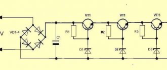
There are various rectification circuits, but the bridge circuit is the most widely used. The principle of its operation is as follows. In the first half-cycle of the alternating voltage, current flows along the path through the diode VD1, resistor R1 and LED VD5. Next, the current returns to the winding through open VD2.
A reverse voltage is applied to the diodes VD3 and VD4 at this moment, so they are locked and no current flows through them (in fact, it only flows at the moment of switching, but this can be neglected).
In the next half-cycle, when the current in the secondary winding changes its direction, the opposite will happen: VD1 and VD2 will close, and VD3 and VD4 will open. In this case, the direction of current flow through resistor R1 and LED VD5 will remain the same.
A diode bridge can be soldered from four diodes connected according to the diagram above. Or you can buy ready-made. They come in horizontal and vertical versions in different housings. But in any case, they have four conclusions. The two terminals are supplied with alternating voltage, they are designated by the sign “~”, both are the same length and are the shortest.
The rectified voltage is removed from the other two terminals. They are designated “+” and “-”. The “+” pin has the longest length among the others. And on some buildings there is a bevel near it.
Capacitor filter
After the diode bridge, the voltage has a pulsating nature and is still unsuitable for powering microcircuits, and especially microcontrollers, which are very sensitive to various kinds of voltage drops. Therefore it needs to be smoothed out. To do this, you can use a choke or a capacitor. In the circuit under consideration, it is enough to use a capacitor. However, it must have a large capacitance, so an electrolytic capacitor should be used. Such capacitors often have polarity, so it must be observed when connecting to the circuit.
The negative terminal is shorter than the positive one and a “-” sign is applied to the body near the first one.
Voltage stabilizer LM7805, LM7809, LM7812
You probably noticed that the voltage in the outlet is not equal to 220 V, but varies within certain limits. This is especially noticeable when connecting a powerful load. If you do not apply special measures, then it will change in a proportional range at the output of the power supply. However, such vibrations are extremely undesirable and sometimes unacceptable for many electronic elements. Therefore, the voltage after the capacitor filter must be stabilized. Depending on the parameters of the powered device, two stabilization options are used. In the first case, a zener diode is used, and in the second, an integrated voltage stabilizer is used. Let's consider the application of the latter.
In amateur radio practice, voltage stabilizers of the LM78xx and LM79xx series are widely used. Two letters indicate the manufacturer. Therefore, instead of LM there may be other letters, for example CM. The marking consists of four numbers. The first two - 78 or 79 - mean positive or negative voltage, respectively. The last two digits, in this case instead of two X's: xx, indicate the value of the output U. For example, if the position of two X's is 12, then this stabilizer produces 12 V; 08 – 8 V, etc.
For example, let's decipher the following markings:
LM7805 → 5V positive voltage
LM7912 → 12 V negative U
Integrated stabilizers have three outputs: input, common and output; designed for current 1A.
If the output U significantly exceeds the input and the maximum current consumption is 1 A, then the stabilizer gets very hot, so it should be installed on a radiator. The design of the case provides for this possibility.
If the load current is much lower than the limit, then you don’t have to install a radiator.
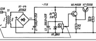
Power supply diagram
The classic design of the power supply circuit includes: a network transformer, a diode bridge, a capacitor filter, a stabilizer and an LED. The latter acts as an indicator and is connected through a current-limiting resistor.
Since in this circuit the current-limiting element is the LM7805 stabilizer (allowable value 1 A), all other components must be rated for a current of at least 1 A. Therefore, the secondary winding of the transformer is selected for a current of one ampere. Its voltage should not be lower than the stabilized value. And for good reason, it should be chosen from such considerations that after rectification and smoothing, U should be 2 - 3 V higher than the stabilized one, i.e. A couple of volts more than its output value should be supplied to the input of the stabilizer. Otherwise it will not work correctly. For example, for LM7805 input U = 7 - 8 V; for LM7805 → 15 V. However, it should be taken into account that if the value of U is too high, the microcircuit will become very hot, since the “extra” voltage is extinguished at its internal resistance.
The diode bridge can be made from 1N4007 type diodes, or take a ready-made one for a current of at least 1 A.
Smoothing capacitor C1 should have a large capacity of 100 - 1000 µF and U = 16 V.
Capacitors C2 and C3 are designed to smooth out high-frequency ripple that occurs when the LM7805 operates. They are installed for greater reliability and are recommendations from manufacturers of stabilizers of similar types. The circuit also works normally without such capacitors, but since they cost practically nothing, it is better to install them.
Reviews about the service
Manuals Reference Programs Homemade radios Medical equipment Library Power supply diagram for a computer Here you can download a fairly decent collection of schematic diagrams of ATX computer power supplies and already outdated AT sources, learn how to check a computer source, get practical advice on repairing it and possible options for upgrading it into the desired amateur radio designs . Sergeev B. The filter consists of a group of capacitors and a choke. This block consists of voltage equalization diodes and a ripple filter.
These power supplies use a special inductor with an inductance higher than that at the input. With a delay of 0, Design features Various connectors are provided for connecting components of a personal computer to the power supply unit. Most often, when a computer power supply breaks down, there are no signs of life in the system unit, the LED indication does not light up, there are no sound signals, and the fans do not spin.
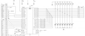
But if you carry out operational control of these parameters, for example, using a controller with a stabilizer function, then the block diagram shown above will be quite suitable for use in computer technology.
Power supply load - thermal control circuit. Sergeev B. Transistors Q 1 and Q 2 open out of phase for equal time intervals t1 and t2 Fig. In power supplies for the ATX design in the future, the source has a changed connector for connecting power to the system board.
Using a multimeter, we check the base-emitter and base-collector junctions, the technique is the same as when checking diodes. Block diagram of a computer power supply. Diagram of a computer power supply. Click to enlarge. ATX power supply repair manual part 1
DIY power supply for 78L05, 78L12, 79L05, 79L08
Often it is necessary to power only one or a pair of microcircuits or low-power transistors. In this case, it is not rational to use a powerful power supply. Therefore, the best option would be to use stabilizers of the 78L05, 78L12, 79L05, 79L08, etc. series. They are designed for a maximum current of 100 mA = 0.1 A, but are very compact and no larger in size than a regular transistor, and also do not require installation on a radiator.
The markings and connection diagram are similar to the LM series discussed above, only the location of the pins differs.
For example, the connection diagram for the 78L05 stabilizer is shown. It is also suitable for LM7805.
The connection diagram for negative voltage stabilizers is shown below. The input is -8 V, and the output is -5 V.
As you can see, making a power supply with your own hands is very simple. Any voltage can be obtained by installing an appropriate stabilizer. You should also remember the transformer parameters. Next we will look at how to make a power supply with voltage regulation.
Simple UPS based on an electronic transformer
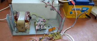
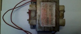
Recently, an electronic transformer for halogen lamps caught my eye in a store. Such a transformer costs a penny - only $2.5, which is several times cheaper than the cost of the components used in it. The block was purchased for experiments. As it turned out later, it did not have protection and during a short circuit there was a real explosion... The transformer was quite powerful (150 watts), so a fuse was installed at the input, which literally burst. After checking, it turned out that half of the components burned out. Repairs will be expensive, and there is no need to waste your nerves and time, it is better to buy a new one. The next day, three transformers for 50, 105 and 150 watts were purchased at once.
It was planned to modify the unit, since it was a UPS - without any filters or protections.
After modification, the result should have been a powerful UPS, the main feature of which was its compactness. To begin with, the unit was equipped with a surge protector.
The inductor was unsoldered from the DVD player's power supply and consists of two identical windings, each containing 35 turns of 0.3mm wire. Only passing through the filter, voltage is supplied to the main circuit. To smooth out low-frequency interference, 0.1 µF capacitors were used (select with a voltage of 250-400 volts). The LED indicates the presence of mains voltage.
I didn’t replace anything on the board, only there is a diode rectifier with filters at the output. Schottky diodes were used (from a computer power supply). To build a bridge we need 4 diode assemblies, there is nothing new in the connection diagram, it was given in one of my articles (link to article)
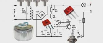
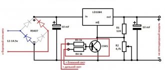
Voltage regulator
A circuit using only one transistor was used. This is the simplest circuit available, contains a couple of components and works very well. The disadvantage of the circuit is that the transistor overheats under heavy loads, but it’s not that bad. In the circuit you can use any powerful bipolar low-frequency transistors of reverse conduction - KT803,805,819,825,827 - I recommend using the last three. The trimmer can be taken with a resistance of 1...6.8k, we take an additional protective resistor with a power of 0.5-1 Watt. The regulator is ready, let's move on.
Protection
Another simple scheme, essentially this is protection against overturning. Literally any relay for 10-15 Amps. You can also use any rectifier diode with a current of 1 ampere or more (the widely used 1N4007 does an excellent job). The LED indicates incorrect polarity. This system turns off the voltage if there is a short circuit at the output or the device being tested is incorrectly connected. The power supply can be used to test the functionality of homemade ULFs, converters, car radios, etc., without having to worry about accidentally mixing up the power polarity.
In the future we will look at some more simple modifications of the electronic transformer, but for now we have a simple, compact and powerful UPS that can be used as a laboratory unit for a beginner.
List of radioelements
| Designation | Type | Denomination | Quantity | Note | Shop | My notepad |
| T1 | Bipolar transistor | KT827A | 1 | Search in the Otron store | To notepad | |
| VD1 | Rectifier diode | 1N4007 | 1 | Search in the Otron store | To notepad | |
| Diode bridge | 1 | Search in the Otron store | To notepad | |||
| C1, C2 | Capacitor | 0.1 µF | 2 | Search in the Otron store | To notepad | |
| C3 | Capacitor | 0.22 µF | 1 | Search in the Otron store | To notepad | |
| C4-C5 | Electrolytic capacitor | 3300 µF | 2 | Search in the Otron store | To notepad | |
| R2 | Resistor | 480 Ohm | 1 | Search in the Otron store | To notepad | |
| R3 | Variable resistor | 1 kOhm | 1 | Search in the Otron store | To notepad | |
| R4 | Resistor | 2.2 kOhm | 1 | Search in the Otron store | To notepad | |
| R5 | Resistor | 1 MOhm | 1 | Search in the Otron store | To notepad | |
| UPS | 1 | Search in the Otron store | To notepad | |||
| L1-L4 | Inductor | 4 | Search in the Otron store | To notepad | ||
| Rel1 | Relay | 10 A | 1 | Search in the Otron store | To notepad | |
| Add all | ||||||
Attached files:
- 5-254.lay (30 Kb)
Tags:
- IIP
- Sprint-Layout