Current, voltage, etc. d.s.
self-induction. When an inductance current (an inductor in which losses can be neglected) is connected to an alternating current circuit (Fig. 178, a), the changing current continuously induces e.
d.s. self-induction
eL= -L ?i / ?t(68)
where ?i/?t is the rate of change of current.
Considering the graph of changes in current strength i (Fig. 178, b), we can establish that the rate of its change ?i/?t will be greatest at times when the angle ?
equals 0; 180 and 360°. Therefore, in these minutes of time e. d.
With. is of greatest importance. At times when the angle ?t is equal to 90° and 270°, the rate of change of current ?i/?t = 0 and therefore e.
d.s. eL= 0.
E.
d.s. According to Lenz's rule, self-induction e is directed so as to prevent the current from changing.
Therefore, in the first quarter of the period, when the current i increases, e. d.s.
eL has a negative value (directed against the current); in the second quarter of the period, when the current i decreases, e. d.s.
eL has a positive value (coincident in direction with the current). In the third quarter of the period, the current i changes its direction and increases, therefore e. d.
With. self-induction eL is directed against the current and has a positive value. In the fourth quarter of the period, the current i decreases and e.
d.s. self-induction eL tends to maintain the previous direction of the current, i.e.
e. has a negative value. Thus, e.
d.s. self-induction eL lags in phase from current i by an angle of 90°.
Since there is no active resistance in the circuit where the inductance L is connected (an ideal inductor is considered), then according to Kirchhoff’s second law u+eL=0, i.e. u = -eLConsequently, the source voltage is always equal in magnitude and opposite in direction e.
d.s. self-induction.
From the consideration of curves (see
rice. 178, b) it is clear that the voltage curve is shifted relative to the current i curve by a quarter of the period, i.e.
at an angle of 90°. In this case, the voltage reaches its highest and zero values earlier than the current. Hence,
Rice.
178. Scheme for connecting inductance to an alternating current circuit (a), curves of current I, voltage and, e.g.
d.s. eL(b) and vector diagram (c)
when an inductance is connected to an alternating current circuit, the current i lags in phase with the voltage by an angle of 90° or, what is the same, the voltage advances the current in phase by an angle of 90° (Fig. 178, c).
Inductive reactance. The resistance of a coil or conductor to alternating current caused by the action of e. d.s.
self-induction is called inductive reactance. It is designated XL and measured in ohms. The physical nature of inductive resistance is completely different from that of active resistance.
E.m.f.
self-induction eL is directed against the applied voltage u, which causes the current to change; according to Lenz's law, it prevents the change in current i, i.e., it provides a certain resistance to the passage of alternating current.
The larger the e. d.
With. self-induction eL is induced in a conductor (coil), the greater they have inductive resistance XL. E.
d.s. self-induction according to formula (68) is directly proportional to the inductance L and the rate of change of current ?i/?t, i.e.
i.e. the frequency of its change f (value?). Therefore the inductive reactance
XL= ?L
Therefore, inductive reactance does not depend on the material from which the conductor (coil) is made, and on the cross-sectional area of the conductor.
Ohm's law for a circuit with inductance
I = U / xL= U / (?L)
Electric power. Let's consider how electrical power changes in an alternating current circuit with inductance. The instantaneous value of power p, equal to the product of the instantaneous values of current i and voltage u, can be obtained graphically by multiplying the ordinates of the current and voltage curves at different angles ?t.
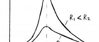
The instantaneous power curve p (Fig. 179, a) is a sinusoid that changes with double frequency 2? compared to the frequency of changes in current i and voltage i.
When examining this curve, it is clear that the power p can have positive and negative values.
During the first quarter of the period, the current and voltage are positive and the power p = ui is also positive. In the second quarter of the period, the current is positive and the voltage is negative; therefore, the power p will be negative. During the third quarter of the period the power becomes positive again, and during the fourth quarter it becomes negative.
The concept of positive and negative electrical power physically determines the direction of energy flow. The positive sign of power means that electrical energy W is transferred from the source to the receiver; the negative sign of power means that electrical energy W is transferred from the receiver to the source. Consequently, when an inductance is connected to an alternating current circuit, a continuous oscillatory process of energy exchange occurs between the source and the inductance, in which no work is created.
In the first and third quarters of the period, the power is positive, i.e. the inductance receives energy W from the source (see
arrows W) and accumulates it in its magnetic field. In the second and fourth quarters of the period, the inductance releases the accumulated energy W to the source. In this case, the flow of current through the circuit is maintained due to the action of e.
d.s. self-induction eL.
Thus, in general, no electrical energy enters the inductive reactance during the period (this is indicated by the fact that the average power value over the period is zero). In order to emphasize this feature of inductive reactance, it is classified as a group of reactances, i.e.
resistances, which in the alternating current circuit as a whole do not consume electrical energy over a period. It should be noted that real inductors receive some energy from the AC source due to the presence of active resistance of the wires from which these coils are made. This energy turns into heat.
Rice. 179. Curves of current i, voltage u and power p when an inductor (a) and a capacitor (b) are connected to the alternating current circuit
Rice. 180. Serial (a) and parallel (b) connections of inductors
Since the average value of power in a circuit with inductance is zero, the concept of reactive power of inductance was introduced to characterize the process of energy exchange between the source and inductance:
QL=ULI
where UL is the voltage applied to the inductance L (rms value).
Reactive power is measured in vars (var) and kilovars (kvar). The name of the unit comes from the first letters of the words volt-ampereactive. Reactive power can also be expressed as
QL= U2L/XL or QL= I2XL
Methods of connecting inductors. In alternating current circuits it is necessary to connect inductors in series and parallel. When connecting inductors in series, the equivalent inductance L is equal to the sum of the inductances; for example, with three coils with inductances L1, L2 and L3 (Fig. 180, a)
Lek = L1+ L2+ L3
In this case, the equivalent inductive reactance
XLek = XL1+ XL2+ XL3
When connecting inductors in parallel (Fig. 180,b), for the equivalent inductance we have:
1 /Lek= 1 /L1+ 1 /L2+ 1 /L3
for equivalent inductive reactance
1 /XLek= 1 /XL1+ 1 /XL2+ 1 /XL3
When current flows through a conductor, a magnetic field always arises around the moving charges. For the case when there is a place in the circuit with several turns, around them the resulting magnetic field penetrates its own conductor, acting as an additional EMF in addition to the main power source. Under the influence of this EMF, an inductive current occurs in the conductor, which in the case of an alternating voltage network also has an alternating character.
In accordance with Lenz's rule, the force of self-induction in all cases counteracts the sieve that caused it.
Since the self-inductive emf, according to this condition, counteracts changes in the circuit, in an alternating current network this factor is taken into account and designated as inductive reactance (XL), measured similarly to active resistance in Ohms.
The magnitude of the inductive reactance is determined by the magnitude of the self-inductive emf, which in turn depends on the inductance of the coil and the frequency of voltage changes in the coil.
XL=ωL,
where L is the inductance of the coil, measured in Henri (H);
ω is the angular frequency of alternating current (rad/sec).
In other words, the higher the frequency of the flowing alternating current and the greater the number of turns in the coil, the greater the inductive reactance.
Inductors in alternating current circuits create toxa-induction, which is in phase ahead of the voltage in the circuit by an angle of 90°. At the same time, during different periods of change in the base voltage, energy is first accumulated in the coil (as the voltage increases in any direction), and then it is released back into the network (during the voltage decreases towards zero). Thus, if we neglect the own active resistance of the coil conductor, on average it does not consume electricity, but only changes the characteristics and nature of the passing current in the circuit over time. That is, all the energy stored in the coil in the first period is then given back to the electrical network. This property has made it possible to widely use inductors in electrical engineering for many purposes: - in as the main accumulating element in stabilizers, which allows you to convert voltage levels; - several inductively interconnected coils form a transformer; - as electromagnets; - in radio communications for receiving and emitting electromagnetic waves (ring antenna, magnetic antenna); - for detecting magnetic fields ;— for heating conductive materials in induction furnaces, and much more. When choosing a coil (inductance) suitable for certain purposes, it is necessary to take into account the frequency in the network, the coil’s own characteristics (resonant frequency, inductance, permissible current, accumulated power, etc. .).In a circuit containing inductance L (Fig.
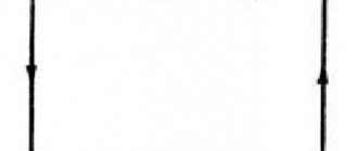
1), the electric current is determined by the combined action of voltage and the energy source and the self-inductive emf e arising in the circuit due to changes in current: Circuit diagram of an alternating current circuit. I = (u + e) : rHence, u = (- e) + ir Let us turn to the simplest conditions , when r = 0. In this case: u= -e = L (?i : ?t)where ?i : ?trate of change of current over time. Figure 1 Curves of instantaneous voltage and current values in a circuit containing only inductance L. Let's consider how the voltage at the inductance terminals must change over time in order for a sinusoidal alternating current to pass through it:i= Imsin?tFor a sinusoidal current, the quantity ?i: ?t has a certain pattern of change over time. It is also sinusoidal, but in phase it is ahead current for a quarter of a period. This can be proven as follows. At moment t, the current strength is: i = Imsin?t and after a very short period of time ?t, the current strength will be: I + ?i = i = Imsin? (t + ?t)change in current:?i = Im Graphs of voltage u and current i in an alternating current circuit with a phase shift. Sine of the sum: sin (?t + ??t) = sin ?t cos ?
?t + cos ?t sin ? ?tMoreover, the cosine of a very small angle, which is ??t, is equal to one: cos??t = 1, and the sine of a very small angle is equal to the corresponding arc, therefore: sin??t= ??tbased on this:?i = Im ( sin ?t + ??t cos ?t – sin ?t) = Im? ?t xcos ?tThus, the rate of change of sinusoidal current:?i : ?t = Im?
cos ?t is the voltage across the inductance proportional to it: u = L (?i : ?t) = Im?cos ?tConsequently, the sinusoidal current in the inductance is also created by a sinusoidal voltage, only this voltage is ahead of the current in phase by a quarter of the period, which corresponds to an arc: (? : 2) or an angle of 90° Thus, the voltage at the inductance terminals is ahead of the current in phase, or, otherwise, the inductive current is a current that is lagging in phase from the voltage. On the right side of the equation, only cos?t depends on time, the largest value of which is cos ?t = 1. Therefore, the maximum value of the voltage across the inductance: Um = Im? L Substitute their effective values into these formulas instead of the maximum values: We get: U = I ? L or I = (U : ? L) This will be Omadl’s law for the circuit (or a section of a circuit) with one inductance. The quantity ?L has the dimension of resistance, since the dimension ?= (1: sec), and the unit of inductance gn = ohm x sec.
The quantity ?L is called inductive reactance and is often abbreviated as x or xL= ?L Essentially, this quantity is a conditional resistance by means of which we take into account the resistance of the self-inductive emf to changes in alternating current, in other words, the reaction (reaction) of inductance to periodic changes in sinusoidal current. Inductive reactance is proportional to the frequency of alternating current, so at direct current it is zero. Many devices and machines of alternating current cannot be switched on at direct voltage, since with alternating current they have a large inductive reactance, and for direct current their resistance is relatively small and the strength of the direct current can be destructive for them (for example, the primary winding of a transformer in a radio receiver). Share a useful article: Home > Theory > Conductor inductance Inductance is one of the concepts of electrical engineering that relates the interaction of electric current in a conductor and a magnetic field. If we take an analogy with mechanics , then inductance can be compared with mechanical inertia. This concept characterizes the electromotive force of self-induction of a conductor.
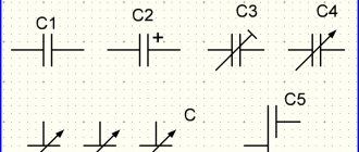
This phenomenon manifests itself in the fact that when the magnitude of the current through the conductor changes, the magnetic flux it creates changes, and it, in turn, causes the appearance of an emf that compensates for the change in current. Inductance on an electrical circuit Any segment of an electrical circuit has inductance, and the longer the conductor, the higher parameter value. In practice, this led to the development of inductors, where the conductor is made in the form of a winding of a number of turns. Inductance is measured in Henry (H), in honor of the scientist who carried out much research in this field. In the diagrams it is indicated by the letter L.
Calculation
Accurate calculation of the inductance value of conductors is quite complex and is performed by means and methods of higher mathematics. It is important to take into account that the inductance of a conductor depends on its location in space in relation to other conductors and dielectrics. This is due to the fact that any substance has a certain effect on the magnetic field, strengthening or weakening its effect, distorting the shape of magnetic lines.
Magnetic field of the winding
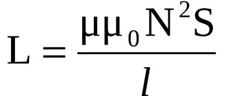
Practical calculations come down to the adoption of simplified models, with a number of tolerances. For example, the magnetic flux in a multi-turn coil in the center and at the edges is very different, therefore, to simplify the calculations of a long coil (solenoid), it is assumed that its length is many times greater than its diameter, and the thickness of the winding is, accordingly, less than the diameter. But even in this case, only an approximate result is obtained.
Calculation methods
There are several basic ways to determine the inductance of a coil. All formulas that will be used in the calculations can be easily found in reference books or on the Internet. The whole calculation process is quite simple and will not be difficult for people with basic mathematical and physical knowledge.
Through current
This calculation is considered the simplest way to determine the inductance of a coil. The formula through current follows from the term itself. What is the inductance of the coil can be determined by the formula: L=Ф/I, where:
- L - circuit inductance (in Henry);
- F is the magnitude of the magnetic flux, measured in webers;
- I is the current strength in the coil (in amperes).
Inductors
The need for circuit elements with large parameter values prompted the creation of coils.
They all represent pieces of insulated wire wound into a spiral with a certain number of turns. The shape of the winding can be different, depending on the requirements for other parameters of the coils. These parameters include:
- Good quality. Characterizes energy losses in the inductor; Own (parasitic) capacitance. For the most part, an undesirable characteristic, since it makes it difficult to configure the circuits and affects phase shifts; The dependence of the inductance value on temperature is the temperature coefficient.
The quality factor is related to the ohmic resistance.
High-frequency voltage causes the appearance of a skin effect, the essence of which is that the current is displaced closer to the surface of the conductor. To minimize the skin effect, the winding is made with Litz wire, in a stranded wire, in which each core is insulated from one another. Also, high-frequency coils are made of silver-plated wire, since silver has less resistance than copper.
Litzendrath
To reduce parasitic capacitance, the windings are performed in a certain way:
- A progressive method, in which the winding pitch on the coils smoothly changes from turn to turn; “Universal” winding; “Pile winding” with a chaotic arrangement of turns; Sectioning, with winding sections with a small number of turns and spacing the sections at a distance from each other.
Winding "Universal"
For coils with a large inductance value, their significant dimensions become a problem. You can increase the inductance without winding a large number of turns by placing a core made of ferromagnetic material inside the winding. Depending on the purpose, requirements for field strength, operating frequency, the following core materials are used:
- Ferrite; Carbonyl iron; Alsifer; Permalloy.
For example, a voltage with a frequency of 50 Hz requires the use of a core made of permalloy in power transformers.
In the microwave range, inductance is usually required to be small, so it can be made from straight or curved pieces of wire soldered into the holes of a printed circuit board, or it can be done directly by printed wiring in the idea of strip lines.
Strip line
Since accurate calculation is practically impossible, most coils in the circuit elements responsible for inductance have the ability to be adjusted. At low frequencies this is regulated by the position of the core, and at high frequencies by changing the relative position and configuration of the turns. What inductance coil should be included in the circuit is calculated based on the parameters of the circuit, and the required value is set during the adjustment process.
Inductor in an AC circuit
In an alternating current circuit, the following process occurs in the inductor:
- the current excites an electromagnetic field in the coil. Since it is variable, the parameters of the electromagnetic field change over time, that is, it is also variable;
- an alternating magnetic field, in accordance with the law of electromagnetic induction, excites an EMF in the coil itself. That's what they call it - self-induced emf. It always goes against the direction of change in current strength. Consequently, in the first half of the half-cycle, when the current increases, the coil restrains this increase. In this case, part of the electrical energy accumulates in the magnetic field generated by the coil;
- in the second half of the half-cycle, the coil, on the contrary, resists the decrease in current strength, returning the energy accumulated in the form of a magnetic field to the circuit.
Thus, the induction coil resists the AC source. This resistance has a different nature than active resistance, which converts electrical energy into heat.
The coil resistance does not consume energy, but only accumulates it and then returns it to the circuit again, changing the nature of the current flow in it. It is called inductive. In contrast to active, it, like the capacitance of a capacitor, is reactive.
The effect is more pronounced the higher the frequency of the alternating current, which is confirmed by the formula for calculating inductive reactance: XL = w*L = 2 π * f * L, where:
- XL —inductive reactance, Ohm;
- W —circular frequency of alternating current, rad/s;
- F —alternating current frequency, Hz;
- L is the inductance of the coil, H.
Inductive reactance, despite a different principle of operation, is measured in the same units as active - Ohm. Thus, in AC circuits, the inductor acts as a current limiter and, unlike in a DC circuit, there is no need to introduce a load.
The dependence of the inductive reactance of the coil on the current frequency allows this element to be used, among other things, to filter high-frequency interference or signals. For example, when installing it in a speaker circuit, the latter reproduces only low frequencies, that is, it plays the role of a subwoofer.
The source consumes part of the power to overcome inductive reactance - this is reactive power (Wр). The rest is called active or useful power (Wa) - it produces useful work. Together, reactive and active power form the total: Wр + Wa = Wpol.
Graph of processes occurring in an inductor
The share of active power is characterized by the cosϕ parameter: cosϕ = Wa / W pos. Total power is usually measured in volt-amperes (VA). It is these units that are indicated in the characteristics of uninterruptible power supplies (UPS) and diesel electric generators. Active power is measured in conventional watts (W).
All of the above is relevant to consumers with electric motors and transformers, since the windings of these elements are essentially inductors. That is, if the nameplate of a computer’s switching power supply indicates that its power is 400 W and cosϕ = 0.7, then from the uninterruptible power supply this device will draw power Wpol = Wa / cosϕ = 400 0.7 = 571.4 VA.
With a large number of such consumers, the cost of reactive power significantly overloads power plant generators, which is why power grids use reactive power compensation (RPC) units.
When the inductor is connected to a DC circuit, the process described in paragraphs 1-3 also takes place, only not all the time, but at the moment of switching on/off.
If you assemble the simplest circuit from a switch, a coil and a lamp installed in series, you can see that the lamp lights up when the circuit is closed with a delay and also goes out with a delay after opening.
This is explained by the fact that the current at the moment of switching on changes from zero value to the maximum, and at the moment of switching off its value changes, albeit very quickly, from maximum to zero. In the first case, the coil accumulates part of the energy in the form of a magnetic field, in the second, it transfers it to the lamp, which is why it burns after the circuit is opened.
Properties
The inductor in an alternating current circuit has distinctive properties that have found their practical application:
Passing through the turns, the alternating voltage leads the current by 90 degrees; Impedance (reactance) increases in direct proportion to the frequency; The current lag and self-induction create the opportunity for energy storage.
When the current flow stops, for example, when the circuit opens, the coil returns stored energy to the circuit, trying to maintain current in the circuit. The faster the current decreases, the more energy will be released. This is expressed in the value of the self-induced emf.
Current and voltage graph
The inductor in a DC circuit has a purely ohmic resistance, which for coils made of thick wire and with a small number of turns can be very small, and the current in the coil can exceed the permissible value.
What have we learned?
An inductor in an alternating current circuit has a reactance proportional to frequency. For the first half of the period, it stores the energy of the electric current in the form of a magnetic field, and for the second half of the period it returns this energy to the electric current. In this case, the current fluctuations in the inductor lag behind the voltage fluctuations by a quarter of a period.
Previous
Physics: Self-oscillations - brief examples from life, formulas for forced oscillations, definition (grade 11)
Next
PhysicsThe postulates of the theory of relativity in brief - the formulas of the second postulate (11th grade physics)
Mutual induction
Coils located next to each other have mutual influence.
The magnetic field created by one of the coils causes the appearance of an emf in the adjacent one. The closer the turns are located, the stronger the mutual influence (this is called the mutual induction coefficient). The greatest influence is observed when the turns are located along one axis or on one magnetic circuit.
AC transformers and coupling coils are based entirely on the phenomenon of mutual induction.
By placing a moving winding close to (inside or outside) a stationary winding, we obtain elements whose mutual and self-inductance can be controlled. Such elements are called variometers.
Sensors
Non-contact sensors based on inductance coils have become widespread. They are based on a sharp change in inductance when any material with certain ferromagnetic properties is introduced into the active zone of the sensor. The consequences of such actions may be:
- Change in resonance frequency of the oscillatory circuit; Change in generation frequency; Disruption of generator oscillations; Change in impedance.
The signal from the sensor is sent to an amplifier or directly to a tracking or actuator device.
Methods for Reducing Unwanted Inductance
In some cases, the inductance of the conductor cannot be neglected; there it is of an undesirable nature. An example would be high-resistance wirewound constant and variable resistors in alternating current circuits.
To reduce inductance, the winding is made using the bifilar method - in two wires. The resulting windings are connected back to back. Thus, in adjacent conductors, current flows towards each other, thus compensating for the formation of an electromagnetic field.
In electrical networks with large inductive load values, the alternating current voltage receives large distortions, which requires the installation of reactive power compensators.
Inductor reactance
Using simple conclusions, physicists derived the formula:
P is constant and equal to approximately 3.14
In this experiment, we received a low-pass filter (LPF). As you have seen yourself, at low frequencies the inductor has almost no resistance to voltage, therefore the amplitude and power at the output of such a filter will be almost the same as at the input. But as the frequency increases, the amplitude decreases. By applying such a filter to a speaker, we can say with confidence that only the bass, that is, the low frequency of the sound, will be amplified.
Video about the inductor:
Application
Inductive elements are used in many areas of radio and electrical engineering:
- In frequency-dependent circuits (oscillatory circuits, filters); In antennas for receiving and emitting radio waves; In pulsed DC voltage stabilizers as a storage element; In electromagnets; For filtering power and limiting current in the circuit. In this capacity, inductors are called chokes.
Currently, there is a trend towards reducing the use of bulky elements. Inductors are practically not amenable to miniaturization and, if possible, they try to replace them with equivalent circuits (gyrators) or use circuit solutions that use other elements. Designing inverter power supplies operating at higher frequencies is one example of miniaturization, since the overall dimensions of transformers, chokes and filters directly depend on the frequency, since the higher the frequency, the lower the required inductance, the smaller the dimensions.