Capacitor in AC circuit
Direct current cannot exist in a circuit containing a capacitor. The movement of electrons is prevented by a dielectric located between the plates. But alternating current can exist in such a circuit, as evidenced by experience with a lamp (see figure below).
Even if such a circuit is actually open, but if alternating current flows through it, the capacitor is either charged or discharged. The current flowing when the capacitor is recharged heats the lamp filament, and it begins to glow.
Let's find how the current strength changes in a circuit containing only a capacitor, if the resistance of the wires and plates of the capacitor can be neglected (see figure above). The voltage across the capacitor will be equal to:
u=φ1−φ2=qC..
Let's take into account that the voltage across the capacitor is equal to the voltage at the ends of the circuit:
qC..=Umaxcos.ωt
Consequently, the charge of the capacitor changes according to the harmonic law:
q=CUmaxcos.ωt
Then the current strength, which is the time derivative of the charge, will be equal to:
i=q´=−CUmaxsin.ωt=CUmaxcos.(ωt+π2..)
Consequently, current fluctuations are ahead of voltage fluctuations across the capacitor by π2.. (see graph below). This means that at the moment when the capacitor begins to charge, the current is maximum and the voltage is zero. After the voltage reaches its maximum, the current becomes zero, etc.
The amplitude of the current is:
Imax=UmaxCω
Let's assume that:
1Cω..=XC
We will also use the effective values of current and voltage. Then we get that:
Definition
I=UXC..
The value of XC, equal to the inverse product of the cyclic frequency and the electrical capacitance of the capacitor, is called capacitance . The role of this quantity is similar to the role of active resistance R in Ohm's law.
Note that during the quarter period when the capacitor is charged to its maximum voltage, energy enters the circuit and is stored in the capacitor in the form of electric field energy. In the next quarter of the period (when the capacitor is discharged), this energy is returned to the network.
Example No. 1. The maximum charge on the capacitor plates of the oscillatory circuit is qmax=10−6 C. The amplitude value of the current in the circuit is Imax = 10−3 A. Determine the period of oscillation (neglect losses due to heating of the conductor).
According to the law of conservation of energy, the maximum value of the energy of the electric field of the capacitor is equal to the maximum value of the magnetic field of the coil:
q2max2C..=LI2max2..
From here:
LC=q2maxI2max..
√LC=qmaxImax..
T=2π√LC=2πqmaxImax..=2·3.1410−610−3..≈6.3·10−3 (s)
Formulas for calculating current in a capacitor
The capacitance of a capacitor connected to an alternating current circuit is calculated by the formula: C = q / U, where:
- C - capacity;
- q is the charge of one of the plates;
- U is the voltage inside.
Capacitance
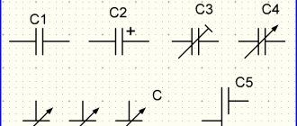
Capacitors come in different shapes, so they are calculated using several formulas:
- flat - C = E × E0 × S / d;
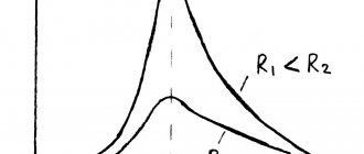
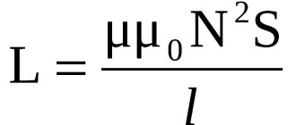
- cylindrical - C=2 π × E × E0 × l / ln(R2 / R1);
- spherical - C = 4 π × E × E0 × R1 × R2 / R2 - R.
Note! The resistance in a variable circuit that a resistor connected to an electrical circuit can provide cannot be calculated, since it is considered infinitely large. However, in this case, this can be done using the formula: Xc = 1 / 2πvC = 1 / wC.
You might be interested in Magnetic starter
The capacitor voltage in an AC circuit is calculated using the following formula: Wp = qd E / 2.
The voltage is calculated using a certain formula
To calculate the voltage across a capacitor in an AC circuit, you need to use current formulas.
Inductor in an AC circuit
Let's assemble two electrical circuits consisting of an incandescent lamp, an inductor and a power source: in the first case, constant, in the second - alternating (see figures “a” and “b” below).
Experience will show that a lamp in a direct current circuit glows brighter compared to one connected in an alternating current circuit. This indicates that the current in the DC circuit is higher than the effective value of the current in the AC circuit.
The result of the experiment is easily explained by the phenomenon of self-induction. When the coil is connected to a constant current source, the current increases gradually. The vortex electric field, which increases with increasing current strength, slows down the movement of electrons. Only after some time does the current reach its maximum value corresponding to a given constant voltage.
If the voltage changes quickly, the current does not have time to reach its maximum value. Therefore, the maximum value of current in an AC circuit with an inductor is limited by the inductance. The greater the inductance and the greater the frequency of the applied voltage, the smaller the amplitude of the alternating current .
Let us determine the current strength in a circuit containing a coil whose active resistance can be neglected (see figure below). To do this, we will find the connection between the voltage on the coil and the self-induction emf in it.
If the coil resistance is zero, then the electric field strength inside the conductor at any time must be zero. Otherwise, according to Ohm's law, the current would be infinitely large. The field strength being equal to zero is possible because the strength of the vortex electric field →Ei generated by the alternating magnetic field at each point is equal in magnitude and opposite in direction to the strength of the Coulomb field →Ek created in the conductor by charges located at the terminals of the source and in the wires of the circuit .
From the equality →Ei=−→Eк it follows that the specific work of the vortex field (i.e. self-induction emf ei ) is equal in magnitude and opposite in sign to the specific work of the Coulomb field .
Considering that the specific work of the Coulomb field is equal to the voltage at the ends of the coil, we can write:
ei=−u
Let us recall that the strength of alternating current varies according to the harmonic law:
i=Imaxsin.ωt
Then the self-induction emf is equal to:
ei=−Li´=−LωImaxcos.ωt
Since u=−ei, the voltage at the ends of the coil is equal to:
u= LωImaxcos.ωt=LωImaxsin.(ωt+π2..)=Umax(ωt+π2..)
The voltage amplitude is:
Umax=LωImax
Consequently, voltage fluctuations on the coil lead current fluctuations by π2.., or current fluctuations lag behind voltage fluctuations by π2.., which is the same thing.
At the moment when the voltage across the coil reaches its maximum, the current is zero (see graph below).
But at the moment when the voltage becomes zero, the current strength is maximum in magnitude. The amplitude of the current in the coil is equal to:
Imax=UmaxLω..
Let us introduce the notation:
Lω=XL
We will also use the effective values of current and voltage instead of amplitudes. Then we get:
Definition
I=UXL..
The quantity XL , equal to the product of the cyclic frequency and inductance, is called inductive reactance . Inductive reactance depends on frequency. Therefore, in a direct current circuit in which there is no frequency, the inductive reactance of the coil is zero.
Example No. 2. A coil with inductive reactance XL = 500 Ohm is connected to an alternating voltage source whose frequency is ν = 1000 Hz. Effective voltage value U = 100 V. Determine the amplitude of the current Imax in the circuit and the inductance of the coil L. Neglect active resistance.
The inductive reactance of the coil is expressed by the formula:
XL=Lω=2πνL
From here:
Since the voltage amplitude is related to its effective value by the relation Umax=U√2, then for the current amplitude we obtain:
Operating principle of a capacitor
Connecting the device to a constant source leads to the fact that at the initial moment there is an accumulation in the plates due to electrostatic induction, and the resistance at this moment is equal to zero. Electrical induction provokes a field to attract opposite charges onto different plates located opposite each other.
You might be interested in: Classes of circuit breakers
This property is called capacitance, which is characteristic of all types of materials, including dielectrics, but in the case of conductors it is significantly greater. That is why the plates are made of conductor. An increase in capacity contributes to the accumulation of more charges on the plates.
Important! When charges accumulate, the field weakens and the two-terminal network increases.
Principle of operation
This happens due to a decrease in space in the plates and the influence of charges of the same name on each other. At the same time, the voltage is equal to the current source. The cessation of electricity in the circuit occurs after the plates are completely filled with electricity. Because of this, induction disappears and only a field remains that holds and does not allow charges to pass through.
Dielectric between plates
The electric current will have nowhere to go, and on a two-terminal network the voltage is equal to the EMF. When the EMF increases, the field acts more strongly on the dielectric due to the lack of space in the plates. If the internal capacitor voltage is higher than the limit values, then the dielectric will break through.
The capacitor is converted into a conductor, and charges are released, causing an electric current to flow. To use a two-terminal network at high voltage, increase the size of the dielectric and increase the distance between the plates while reducing the capacitance. The dielectric is located between the plates and does not allow the constant to pass through, performing a barrier function in relation to it.
Electrical induction
Note! It is direct voltage that can form electrostatic induction, but only in the case of a short circuit at the time of charging the capacitor. Thanks to this mechanism, energy is saved until the consumer is connected to it.
Capacitor in DC circuit
To understand how a storage device works in a DC circuit, you need to add a light bulb to the circuit, which will light up only during charging, during which the voltage remains from the electric current, as if catching up with it due to a smooth increase. Charges of electricity take some time to move to the plates; this is precisely the charging time, the duration of which is determined by the frequency and voltage capacitance. When charging is complete, the light goes out and no constant current flows through the passive electronic component.
Capacitor in AC circuit
If the polarity of the source is changed, this will lead to the discharge of the capacitor in the alternating current circuit and its recharging. A constant electrostatic induction is formed with an alternating one. Whenever electricity changes its direction, the charging and discharging mechanism is triggered, which is why it passes the variable. An increase in frequency leads to a decrease in the capacitive reactance of a two-terminal network.
You might be interested in DIF or RCD
Capacitor in a constant circuit
§51. Inductance in AC circuit
Current, voltage, etc. d.s. self-induction . When an inductance current (an inductor in which losses can be neglected) is connected to an alternating current circuit (Fig. 178, a), the changing current continuously induces e. d.s. self-induction
eL = -L ?i / ?t (68)
where ?i/?t is the rate of change of current.
Considering the graph of changes in current strength i (Fig. 178, b), we can establish that the rate of its change ?i/?t will be greatest at times when the angle ? equals 0; 180 and 360°. Therefore, in these minutes of time e. d.s. is of greatest importance. At times when the angle ?t is equal to 90° and 270°, the rate of change of current ?i/?t = 0 and therefore e. d.s. eL = 0.
E.m.f. According to Lenz's rule, self-induction e is directed so as to prevent the current from changing. Therefore, in the first quarter of the period, when the current i increases, e. d.s. eL has a negative value (directed against the current); in the second quarter of the period, when the current i decreases, e. d.s. eL has a positive value (coincident in direction with the current). In the third quarter of the period, the current i changes its direction and increases, therefore e. d.s. self-induction eL is directed opposite the current and has a positive value. In the fourth quarter of the period, the current i decreases and e. d.s. self-induction eL tends to maintain the previous direction of the current, i.e. it has a negative value. Thus, e. d.s. self-induction eL lags in phase from current i by an angle of 90°.
Since there is no active resistance in the circuit where the inductance L is connected (an ideal inductor is considered), then according to Kirchhoff’s second law u+eL=0, i.e. u = -eL Therefore, the source voltage is always equal in value and opposite in value direction e. d.s. self-induction.
From an examination of the curves (see Fig. 178, b) it is clear that the voltage curve is shifted relative to the current i curve by a quarter of the period, i.e., by an angle of 90°. In this case, the voltage reaches its highest and zero values earlier than the current. Hence,
Rice. 178. Scheme for connecting inductance to an alternating current circuit (a), curves of current I, voltage and emf. eL (b) and vector diagram (c)
when an inductance is connected to an alternating current circuit, the current i lags in phase with the voltage by an angle of 90° or, which is the same, the voltage advances the current in phase by an angle of 90° (Fig. 178, c).
Inductive reactance. The resistance of a coil or conductor to alternating current caused by the action of e. d.s. self-induction is called inductive reactance. It is designated XL and is measured in ohms. The physical nature of inductive resistance is completely different from that of active resistance. E.m.f. self-induction eL is directed against the applied voltage u, which causes the current to change; according to Lenz's law, it prevents the change in current i, i.e., it provides a certain resistance to the passage of alternating current.
The larger the e. d.s. self-induction eL is induced in the conductor (coil), the greater the inductive resistance XL they have. E.m.f. self-induction according to formula (68) is directly proportional to the inductance L and the rate of change of current ?i/?t, i.e., the frequency of its change f (value ?). Therefore the inductive reactance
XL = ?L
Therefore, inductive reactance does not depend on the material from which the conductor (coil) is made, and on the cross-sectional area of the conductor.
Ohm's law for a circuit with inductance
I = U / xL = U / (?L)
Electric power. Let's consider how electrical power changes in an alternating current circuit with inductance. The instantaneous value of power p, equal to the product of the instantaneous values of current i and voltage u, can be obtained graphically by multiplying the ordinates of the current and voltage curves at different angles ?t. The instantaneous power curve p (Fig. 179, a) is a sinusoid that changes with double frequency 2? compared to the frequency of changes in current i and voltage i.
When examining this curve, it is clear that the power p can have positive and negative values. During the first quarter of the period, the current and voltage are positive and the power p = ui is also positive. In the second quarter of the period, the current is positive and the voltage is negative; therefore, the power p will be negative. During the third quarter of the period the power becomes positive again, and during the fourth quarter it becomes negative.
The concept of positive and negative electrical power physically determines the direction of energy flow. The positive sign of power means that electrical energy W is transferred from the source to the receiver; the negative sign of power means that electrical energy W is transferred from the receiver to the source. Consequently, when an inductance is connected to an alternating current circuit, a continuous oscillatory process of energy exchange occurs between the source and the inductance, in which no work is created. In the first and third quarters of the period, the power is positive, that is, the inductance receives energy W from the source (see arrows W) and accumulates it in its magnetic field. In the second and fourth quarters of the period, the inductance releases the accumulated energy W to the source. In this case, the flow of current through the circuit is maintained due to the action of the emf. With. self-induction eL.
Thus, in general, no electrical energy enters the inductive reactance during the period (this is indicated by the fact that the average power value over the period is zero). In order to emphasize this feature of inductive reactance, it is classified as a group of reactive resistances, i.e. resistances that, in an alternating current circuit as a whole, do not consume electrical energy over a period. It should be noted that real inductors receive some energy from the AC source due to the presence of active resistance of the wires from which these coils are made. This energy turns into heat.
Rice. 179. Curves of current i, voltage u and power p when an inductor (a) and a capacitor (b) are connected to the alternating current circuit
Rice. 180. Serial (a) and parallel (b) connections of inductors
Since the average value of power in a circuit with inductance is zero, the concept of reactive power of inductance was introduced to characterize the process of energy exchange between the source and inductance:
QL = ULI
where UL is the voltage applied to the inductance L (rms value).
Reactive power is measured in vars (var) and kilovars (kvar). The name of the unit comes from the first letters of the words volt-ampereactive. Reactive power can also be expressed as
QL = U2L/XL or QL = I2XL
Methods for connecting inductors. In AC circuits, inductors have to be connected in series and in parallel. When inductors are connected in series, the equivalent inductance Lek is equal to the sum of the inductances; for example, with three coils with inductances L1, L2 and L3 (Fig. 180, a)
Lek = L1+ L2 + L3
In this case, the equivalent inductive reactance
XLek = XL1+ XL2 + XL3
When connecting inductors in parallel (Fig. 180,b), for the equivalent inductance we have:
1 /Lek = 1 /L1 + 1 /L2 + 1 /L3
for equivalent inductive reactance
1 /XLek = 1 /XL1 + 1 /XL2 + 1 /XL3