Capacitor formulas
For any capacitor the formula is valid:
where C is the capacitance of the capacitor; q is the charge value of one of the capacitor plates; – potential difference between its plates.
The capacitance of a capacitor with a dielectric between its plates (C) (the dielectric constant of which is several times greater than the capacitance of the same air capacitor ():
To calculate the capacitance of a flat capacitor, use the formula:
where is the electrical constant; S – area of each (or smallest) plate; d – distance between plates.
The capacitance of a flat capacitor containing N layers of dielectric (the thickness of the i-th layer is equal to , the dielectric constant of the i-th layer is defined as:
The electrical capacitance of a cylindrical capacitor is calculated as:
where l is the height of the cylinders; – radius of the outer lining; – radius of the inner lining.
The capacitance of a spherical (ball) capacitor is found by the formula:
where are the radii of the capacitor plates.
What is ESR?
ESR - Equivalent Series Resistance - is one of the parameters of a capacitor that characterizes its active losses in an alternating current circuit. In equivalent, it can be represented as a resistor connected in series with a capacitor, the resistance of which is determined mainly by dielectric losses, as well as the resistance of the plates, internal contact connections and leads. In the Russian abbreviation - Equivalent Series Resistance - EPS.
Losses in the dielectric, caused by the peculiarities of its polarization, constitute the main part of the losses in the capacitor and are determined by the material, as well as the thickness of the dielectric layer.
Polarization is a limited displacement of bound dielectric charges in an electric field.
There is no need to consider in detail the processes of all types of polarization here, but it can be briefly explained as follows: Dielectric particles with a charge, under the influence of an alternating electric field, are forced to perform involuntary mechanical vibrations due to their reorientation and displacement (polarization). In the dielectric layers close to the plates, charges, without leaving their bonds, actively participate in all processes of voltage and current formation in the capacitor, just like conductors. In essence, the thickness of the actual dielectric layer is reduced. As a result, the capacitance of the capacitor increases significantly, but, due to the inertia and internal friction of the associated particles, the processes are accompanied by the release of heat and energy losses in the conductive layers of the dielectric. That is, these polarized layers have active resistance to electric current. With increasing frequency, dielectric losses increase proportionally for the same reason - the mechanical inertia of polarized charges.
The resistance of the conductive layers of the dielectric is added in series with the resistance of the plates, leads and contact connections. As a result, a total active resistance R
— Equivalent Series Resistance (ESR). In essence, it is a resistor connected in series with a capacitor.
In this case, the phase angle between current and voltage will not be 90°, as in an ideal capacitor, but somewhat smaller. Angle tangent δ
, which makes up this difference from 90°, is called the loss tangent.
The tangent of the angle is determined by the ratio of active resistance to reactive resistance R/Xc
, as a trigonometric function of the ratio of the two legs of the resistance triangle shown in the figure above.
In electrolytic capacitors, a significant part of the ESR is the resistance of the liquid electrolyte, which is used as one of the plates to ensure maximum contact area with the dielectric. The active resistance of the electrolyte in real capacitors is usually comparable to tenths or even hundredths of an Ohm at 20°C, but for high-capacity capacitors used in SMPS rectifier filters at an operating frequency of the order of 100 kHz, when its reactance is measured in thousandths of an Ohm, this value may account for the main losses, and will decrease significantly as it warms up. At operating temperature, the magnitude of dielectric losses at such frequencies is usually several times greater.
The resistance of the electrolyte depends on temperature due to changes in the degree of its viscosity and ion mobility.
During operation, the dielectric and electrolyte are heated by alternating current, due to which the resistance of the electrolyte is significantly reduced, then the ESR of the capacitor will be determined primarily by its dielectric losses, which will continue to heat the capacitor within the limits allowed by calculations. But, in cases of heating to the boiling point, the electrolyte loses its original properties and upon subsequent cooling it becomes more viscous, which impairs the mobility of ions and increases the active resistance. Further operation will cause even greater heating and deterioration of the quality of the electrolyte, which will subsequently lead to the unsuitability of the capacitor for further operation. Faulty capacitors in which the electrolyte has boiled are usually identified visually by a swollen and depressurized housing.
For the reliable operation of electrolytic capacitors, the correct choice of its type, rating and maximum voltage is very important, depending on the modes and operating conditions. For rectifier filters in converters operating at frequencies of tens or hundreds of kilohertz, manufacturers produce special capacitors with low ESR and indicate the AC impedance (impedance Z) for all ratings in the tables. The type of such capacitors is accompanied by a mark in the technical documentation - Low impedance or Low ESR.
To analyze the state of the electrolyte and internal connections of electrolytic capacitors, ESR meters or probes are used, which can be made based on different measurement principles and error requirements. Most simple ESR probes and testers are based on the principle of impedance measurement. They have their own significant advantage - a low-impedance input, which allows you to test capacitors without removing them from the board. More information about measurement methods can be found on the page - ESR measurement.
Along with the deterioration of the quality of the electrolyte, the active resistance in capacitors often increases due to deterioration of the contacts of the plates with the terminals, up to a complete break. In electrolytic ones this happens more often, in metal-ceramic ones less often; television technicians are well aware of all these cases. And repairmen of the older generation, who saw Soviet tube TVs, well remember paper capacitors, which were sometimes pressed with pliers to seal the contact connections inside, and they still worked for some time.
What is the table for? Most probes and testers, usually LED or pointer type, measure impedance - the total resistance of the capacitor (active and reactive). It is more difficult to measure the active separately, but it is the loss - the ESR value. When measuring capacitances less than 100 microfarads, the reactive component is already commensurate with, and sometimes greater than, the ESR value, and significantly affects the result. And in capacitors less than 10 µF, the ESR value is many times smaller and its share is insignificant in the total reading. It is impossible to accurately measure their ESR with such probes, but it is possible to identify faulty capacitors. In other words, the reactance in the readings of such devices is an inconvenient error depending on the capacitance of the capacitor. It must be taken into account when assessing the quality of a capacitor for different capacities. In addition, ESR depends on the thickness of the electrolyte and dielectric layers. For high voltage and large capacitors, these values are taken into account by manufacturers depending on the application. There is no proportional dependence of ESR on other parameters of the capacitor, therefore tables are used in practice to assess its quality.
All existing tables are conditional and do not always objectively determine acceptable values for all meters. They are often published to popularize sites, so it is important to understand the essence of the meanings in the tables. Moreover, different probes operate on different principles or frequencies (from 10 to 100 kHz), the difference in readings by 5 or 10 times may differ from the tabulated ones only for this reason. It is very useful to measure the ESR values yourself for new capacitors from different manufacturers and create your own table for your probe. These will already be real indicators. Then they can be compared with faulty capacitors and with the values of their reactance in order to draw some conclusions about criticality. In power supply converters, parasitic tenths, sometimes hundredths of an Ohm heat the capacitor, and if your meter can show them, that’s not bad. The pulse current in capacitors reaches tens of Amperes and active tenths of an Ohm for 10 Amps are already real Watts - heating. The dimensions of the capacitor are also significant; they will cool the electrolyte; this must be taken into account when choosing the type of capacitor in powerful converters. Practice has shown that thin Low ESR capacitors, installed when replacing power supplies instead of large conventional ones, often do not last long there, overheat, boil and swell, sometimes after just a few months of operation.
For the most popular capacitor in SMPS, 1000uF x 25V, tables often indicate 0.08 Ohm as the norm. And in other tables it is 0.8 Ohm. Which device measures what, who determined its norm and for which circuits are mysteries. Use your device to compare this new capacitor from different manufacturers, including those marked Low ESR, then the assessment will be more objective.
Bob Parker's table for the K7214 ESR meter
| uF\V | 10V | 16V | 25V | 35V | 50V | 160V | 250V |
| 1 uF | 14 | 16 | 18 | 20 | |||
| 2.2 uF | 6 | 8 | 10 | 10 | 10 | ||
| 4.7 uF | 15 | 7.5 | 4.2 | 2.3 | 5 | ||
| 10uF | 6 | 4 | 3.5 | 2.4 | 3 | 5 | |
| 22uF | 5.4 | 3.6 | 2.1 | 1.5 | 1.5 | 1.5 | 3 |
| 47 uF | 2.2 | 1.6 | 1.2 | 0.5 | 0.5 | 0.7 | 0.8 |
| 100 uF | 1.2 | 0.7 | 0.32 | 0.32 | 0.3 | 0.15 | 0.8 |
| 220 uF | 0.6 | 0.33 | 0.23 | 0.17 | 0.16 | 0.09 | 0.5 |
| 470 uF | 0.24 | 0.2 | 0.15 | 0.1 | 0.1 | 0.1 | 0.3 |
| 1000 uF | 0.12 | 0.1 | 0.08 | 0.07 | 0.05 | 0.06 | |
| 4700 uF | 0.23 | 0.2 | 0.12 | 0.06 | 0.06 |
Let's calculate the rounded reactance for popular ratings at an average probe frequency of 20 kHz in order to at least have an idea of the order of their ideal values.
Let me remind you once again that there can be no proportion between ESR and these values. Moreover, taking into account the design features of electrolytic capacitors for different dimensions and voltage. I repeat. This is just reactance, which has more
value when measuring
smaller
, as is the actual error for impedance-based probes. That is, the net ESR value of a 100 µF and 1 µF capacitor can be the same, but the device will show a difference of tens of times, because it will add a capacitive value, which will be decisive for the device readings at the measured frequency for small capacitors.
Reactance of capacitors, frequency 20 kHz: 1000 µF - 0.008 Ohm. 470 uF - 0.017 Ohm. 220 uF - 0.036 Ohm. 100 uF - 0.08 Ohm. 47 uF - 0.17 Ohm. 22 uF - 0.36 Ohm. 10 uF - 0.8 Ohm. 4.7 uF - 1.7 Ohm. 2.2 uF - 3.6 Ohm. 1 µF - 8 ohms. 0.47 uF - 17 Ohms. A calculator for calculating the reactance of capacitors will help.
More sophisticated digital devices are able to measure exact values while charging a capacitor with direct current, and calculate its capacitance and ESR without the reactive component. But DC measurement does not take into account dielectric losses, which directly depend on frequency. In addition, capacitors need to be desoldered from the board for such measurements.
Testers usually quickly check capacitors for malfunctions without desoldering them, and this is a significant gain in efficiency for the repairman. He does not always need accurate readings from complex instruments; more often it is important to timely and correctly identify the faulty part in the device. Masters simply get used to errors in reactivity in practice when they use the same probe for years.
Thank you for your attention!
Comments and suggestions are accepted and welcome!
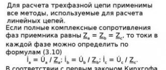
What is a capacitor?
A capacitor consists of two conducting plates located very close to each other and separated by a dielectric. Applying a constant voltage to the plates will cause current to flow and the appearance on both covers of charges equal in magnitude, but opposite in sign: negative on one and positive on the other. Disabling the power source will result in the charge not disappearing instantly, ignoring the phenomenon of its gradual leakage. Then, if the part covers are connected to some kind of load, for example, to a flash, the capacitor will discharge itself and return all the energy accumulated in it to the flash.
Capacitor designation
Capacitors are passive components that store electrical charge. This simple function is used in various cases:
- With alternating current.
- At constant current.
- In analog networks.
- In digital circuits.
Examples of using devices: synchronization systems, signal shaping, communications, filtering and signal smoothing, setting up televisions and radios.
Application in practice
The properties of a capacitor are used in the design of various filters. The effect of capacitance in this case depends on the method of connecting the part:
- If it is connected in parallel with the load, you will get a filter that blocks high frequencies. As they increase, the resistance of the capacitor decreases. Accordingly, the load at high frequencies is shunted more than at low frequencies.
- If the part is connected in series with the load, you will get a filter that delays low frequencies. This circuit also does not allow DC voltage to pass through.
- Another area of application is separating the variable component from the constant one. For example, in the final stages of audio amplifiers. The higher the capacitance, the lower the frequency the connected speaker can reproduce.
In power supply filters, along with capacitance, the property of accumulating and releasing charge is also used. When the load increases, the charged filter capacity is discharged, releasing additional energy. It also suppresses ripple and other parasitic signals by passing them through itself and connecting them to a common wire. Thus, smoothing and maintaining the load voltage within specified limits is ensured, and unwanted inter-stage connections that cause unstable operation are eliminated.
Capacitor resistance measurement.
Capacitor charge formula
To perform charging, the capacitor must be connected to a DC circuit. A generator can be used for this purpose. Every generator has internal resistance. When the circuit is closed, the capacitor is charged. A voltage appears between its plates equal to the electromotive force of the generator: Uc = E.
The plate connected to the positive pole of the generator is charged positively (+q), and the other plate receives an equal charge with a negative value (-q). The amount of charge q is directly proportional to the capacitance of the capacitor C and the voltage on the plates Uc. This dependence is expressed by the formula: q = C x Uc.
During the charging process, one of the capacitor plates gains and the other loses a certain number of electrons. They are transferred through an external circuit under the influence of the electromotive force of the generator. This movement is an electric current, also known as charging capacitive current (Icharge).
The charging current flows in the circuit in almost thousandths of a second, until the moment the capacitor voltage becomes equal to the electromotive force of the generator. The voltage increases smoothly and then gradually slows down. Further, the capacitor voltage value will be constant. During charging, a charging current flows through the circuit. At the very beginning, it reaches its maximum value, since the capacitor voltage has a zero value. According to Ohm's law, Izar = E/Ri, since the entire emf of the generator is applied to the resistance Ri.
Capacitor resistance.
Let's close the circuit. The capacitor began to charge and immediately became a source of current, voltage, E.M.S.. The figure shows that the E.M.S. of the capacitor is directed opposite the current source charging it.
We advise you to study Antenna for car radioThe opposition of the electromotive force of a charged capacitor to the charge of this capacitor is called capacitance.
All the energy expended by the current source to overcome capacitance is converted into the energy of the electric field of the capacitor. When the capacitor is discharged, all the energy of the electric field will return back to the circuit in the form of electric current energy. Thus, capacitance is reactive, i.e. not causing irreversible energy losses.
Why doesn't direct current pass through the capacitor, but alternating current does?
Let's turn on the DC circuit. The lamp will flash and go out, why? Because a capacitor charging current passed through the circuit. As soon as the capacitor is charged to the battery voltage, the current in the circuit will stop.
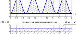
Now let's close the AC circuit. In the first quarter of the period, the voltage on the generator increases from 0 to maximum. The circuit carries a capacitor charging current. In the second quarter of the period, the voltage on the generator decreases to zero. The capacitor is discharged through the generator. After this, the capacitor is charged and discharged again. Thus, the charge and discharge currents of the capacitor flow through the circuit. The light will remain on continuously.
In a circuit with a capacitor, current flows throughout the entire closed circuit, including the dielectric of the capacitor. An electric field is generated in a charging capacitor which polarizes the dielectric. Polarization is the rotation of electrons in atoms in elongated orbits.
The simultaneous polarization of a huge number of atoms produces a current called displacement current.
Thus, current flows in the wires and in the dielectric of the same magnitude.
capacitor is determined by the formula
At active resistance, the voltage U act and current I are in phase. At capacitive reactance, the voltage Uc lags behind the current I by 90 0. The resulting voltage applied by the generator to the capacitor is determined by the parallelogram rule. This resulting voltage lags behind the current I by some angle φ, always less than 90 0.
Formula for the capacitance of a cylindrical capacitor
Now let's talk about how to find the capacitance of a cylindrical capacitor. These include capacitors consisting of two metal cylinders inserted into one another. A dielectric is placed between them to separate them. The formula for the capacitance of a capacitor is as follows:
Here we see several new variables:
- l – height of the cylinder;
- R1 and R2 – radius of the first and second (outer) cylinders;
- ln is not a variable, but a mathematical symbol for the natural logarithm. Some calculators have it.
You should always remember that all quantities must be converted to a single system; the table below shows the international systems of units (SI).
It shows that all distances must be reduced to a meter.
It is also worth paying attention to the quality of the dielectric. If the thickness of the dielectric affects only the capacitance of the capacitor, then its quality affects energy conservation. In other words, a capacitor with a high-quality dielectric will have less self-discharge.
Quality can be determined by the number next to the substance; the larger it is, the better the quality. The comparison is made using vacuum, the value of which is equal to unity.
What determines the resistance of capacitors in AC circuits?
Its indicators depend not only on the capacitive characteristics of the latter, but also on the frequency characteristics of the electric current flowing through the circuit. When we talk about the resistance of a resistor, we are talking about the parameters of the resistor itself, for example, material, shape, but there is absolutely no relationship between its resistance and the frequency indicators of the circuit electricity (we are talking about an ideal resistor, the parasitic parameters of which are not typical). When it comes to a device for storing energy and charging an electric field, everything is different. A capacitor of the same capacitance at different current frequencies has different levels of resistance. The amplitude of the electricity flowing through it at a constant voltage amplitude has a different value.
Considering this formula for the resistance of a capacitor in an alternating current circuit, what conclusions can be drawn? As the signal frequency increases, the electrical resistance of the capacitor decreases.
As the capacitive characteristics of the device for accumulating charge and energy of the electric field Xc of alternating electricity passing through it increase, it will tend downward.
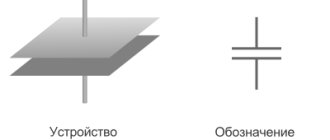
The graph displaying this capacitor value for a variable circuit current has the shape of a hyperbola
The moment the frequency values approach zero marks on the axis (when the alternating electric current becomes similar in its parameters to constant), is accompanied by an increase in Xc of the capacitor to unlimited values. This is true: it is known that a DC mains capacitor is actually an open circuit. The actual electrical resistance, of course, is not infinite; it is limited by the level of capacitor leakage. But its values remain at a high level, which cannot be ignored.
As the frequency digits increase to the level of infinite values, the capacitance of the electric capacitor tends to zero. This characterizes ideal models. In real conditions, a capacitor has unpleasant characteristics (such as inductance and leakage resistances), so the capacitance decreases up to certain values, after which it increases.
Note! When a capacitor is connected to an electrical circuit with variable parameters, its power is not wasted, because the phase characteristics of voltage and current are shifted by 90° in relation to each other. In one quarter of the period, the electric capacitor is charged (energy is stored in its electric field), the next time it is discharged, the energy goes back into the circuit. Its electrical resistivity is watt-free and reactive.
Capacitor resistance to alternating voltage
When a capacitor is connected to an alternating current circuit, current flows freely through the capacitor. This can be explained very simply: a process of constant charging and discharging of the capacitor occurs. In this case, they say that the circuit contains capacitive reactance of the capacitor, in addition to active resistance.
And so, a capacitor, which is connected to an alternating current circuit, behaves as a resistance, that is, it affects the current flowing in the circuit. We denote the value of capacitance as , its value is related to the frequency of the current and is determined by the formula:
where is the frequency of alternating current; — angular frequency of current; C is the capacitance of the capacitor.
If a capacitor is connected to an alternating current circuit, then no power is expended in it, because the phase of the current is shifted relative to the voltage by . If we consider one period of current oscillation in the circuit (T), then the following happens: when the capacitor is charged (this amounts to ), energy is stored in the capacitor field; in the next period of time (), the capacitor discharges and releases energy into the circuit. Therefore, capacitive reactance is called reactive (watt-free).
It should be noted that in every real capacitor, real power (loss power) is still spent when alternating current flows through it. This is caused by changes occurring in the state of the dielectric of the capacitor. In addition, there is some leakage in the insulation of the capacitor plates, so a small active resistance appears, which is, as it were, connected in parallel with the capacitor.
How to calculate Xc
The current strength of a circuit with constant voltage readings at the time of operation of the electric capacitor is equal to 0. Its value in a circuit with alternating voltage after connecting the capacitor I? 0. As a result, the capacitor imparts less Xc to a chain with a variable voltage than to a chain with a constant voltage.
Formula for calculating voltage in one second
Formula for calculating the amount of electric current in an instant
It turns out that voltage changes differ in phase from current changes by π/2.
According to the law formulated by Ohm, the strength of the electric current is directly proportional to the magnitude of the circuit voltage. Formula for calculating the largest values of voltage and current:
The highest values of voltage and current can be calculated using the formula
The final formula for calculating capacitance in an AC circuit
f is an indicator of the frequency of intermittent current, measured in hertz;
ω is an indicator of the angular frequency of the current;
About real capacitor
A real capacitor has two resistances at the same time: active and capacitive. They should be considered connected in series.
The voltage applied by the generator to the active resistance and the current flowing through the active resistance are in phase.
We advise you to study Lithium ion battery
The voltage applied by the generator to the capacitance and the current flowing through the capacitance are shifted in phase by 90. The resulting voltage applied by the generator to the capacitor can be determined using the parallelogram rule.
At the active resistance, the voltage Uact and current I are in phase. At capacitive reactance, the voltage Uc lags the current I by 90. The resulting voltage applied by the generator to the capacitor is determined by the parallelogram rule. This resulting voltage lags behind the current I by some angle φ, always less than 90.
How is capacitive electrical resistance measured?
R is represented by the ratio of voltage to current in a closed electrical circuit, according to Ohm's law. Units of measurement are Ohms. Xc, as its variant, is also measured in Ohms.
Capacitors are used in the manufacture of filters. When connected in parallel to a circuit, it is capable of delaying high frequencies, and when connected in series, it removes low frequencies. They are also used to cut off the variable part from the constant part. It is indispensable in radio engineering, in the production of proximity sensors, and for monitoring production processes. Technologies with the properties described above are used in all areas of industry.
Methods of connecting elements
Mounting the product on the board can be vertical or horizontal. When using several products, they can be connected to each other in different ways.
Parallel connection
To organize it, you need to connect a group of parts to an electrical circuit so that the plates of all parts are connected directly to the switching points. Since all components receive charge from the same current source, they will have the same potential difference. But since the charge accumulates on each product separately, the amount of electricity on the group can be expressed as the sum of the quantities on its parts.
This is also true for capacitive data - the value for the configuration is equal to the sum of the values of each unit. Therefore, such a group can be considered equal to one capacitor, the capacitive parameter of which is equal to the sum of those for all parts.
Serial connection
This scheme involves connecting devices one after another, when only the two outermost products are connected to the connection points in the circuit. The amount of electricity for each part will be the same. In this case, the less capacitive the device, the higher the voltage value will be observed on it.
Important! The capacitance value of such a system will be even less than that of a device with the lowest value. The relationship looks like this: 1/C = 1/C1 + 1/C2 + 1/C3 + ... Based on it, we can directly derive formula C. For two elements: C = C1*C2 / C1+C2.
Serial connection
Mixed compound
Such a complex structure contains fragments with the above two types of connections. To calculate the total capacity, the circuit is divided into simple blocks, consisting only of parts connected in one way. Find equivalent values for each block and then draw the diagram again in a simplified form. Calculate data for the resulting system.
To be able to select a suitable capacitor set, you need to be able to find out the capacitance data. It is also important to know how the indicator is calculated for a configuration of several parts connected to each other in one way or another.
Unit and calculation formulas
Capacitance, an electrical property capable of storing charges, is measured in farads (F) and is designated C. The value is named after the English physicist Michael Faraday. A capacitor with a capacity of 1 farad is capable of storing a charge of 1 coulomb on the plates with a voltage of 1 volt. The value of C is always positive.
Mathematical expression for farad
The capacitance of a capacitor is a constant value indicating the potential ability to store energy. The amount of charge stored at any given moment is determined by the equation Q=CV, where V is the applied voltage. Thus, by adjusting the voltage on the plates, the charge can be increased or decreased. This capacitance formula in the form C=Q/V in unit values determines how the capacitance of a capacitor is measured in SI and is the mathematical expression for the farad.
Electronics experts consider the unit of one farad not very practical, since it represents a huge value. Even 1/1000 F is a very large capacity. Typically, the following values are used for actual electrical components:
- picofarad - 10-12 F;
- nanofarad - 10-9 F;
- microfarad - 10-6 F.
You might be interested in the material from which the artificial ground electrode should be made
The dielectric constant
The factor by which an insulator determines the capacitance of a capacitor is called dielectric constant. The generalized formula for calculating the capacitance of a parallel plate capacitor is represented by the expression C= ε (A / d), where:
- A is the area of the smaller plate;
- d is the distance between them;
- ε is the absolute permeability of the dielectric material used.
The dielectric constant of vacuum ε0 is a constant and has a value of 8.84x10⁻¹² farads per meter. Typically, the conductive plates are separated by a layer of insulating material rather than a vacuum. To find the capacitance of a capacitor whose plates are in the air, you can use the value ε0. The difference in dielectric constant of the atmosphere and vacuum can be neglected, since their values are very close.
In practice, formulas for finding the capacitance of a capacitor use relative dielectric constant as a coefficient, meaning how much the electric field between charges decreases in a dielectric compared to a vacuum. Some values of this value for various materials:
- 1.0006 - air;
- 2.5—3.5 — paper;
- 3—10 — glass;
- 5-7 - mica.
Since the efficiency of a capacitor depends on the insulator used in it, its quality as a storage device can be determined through its specific capacitance - a value equal to the ratio of the capacitance to the volume of the dielectric.
Device characteristics
The most important characteristic of a storage device is capacity. The charging time depends on it when the device is connected to a power source. The discharge time is directly related to the value of the load resistance: the higher it is, the faster the process of releasing the accumulated energy occurs. This capacity is determined by the following expression:
C = E*Eo*S / d, where E is the relative dielectric constant of the medium (reference value), S is the area of the plates, d is the distance between them.
In addition to capacity, the capacitor is characterized by a number of parameters, such as:
- specific capacitance - determines the ratio of the capacitance to the mass of the dielectric;
- operating voltage - the nominal value that the device can withstand when applied to the plates of the element;
- temperature stability - the range in which the capacitance of the capacitor practically does not change;
- insulation resistance - characterized by the self-discharge of the device and determined by the leakage current;
- equivalent resistance - consists of losses generated at the terminals of the device and the dielectric layer;
- absorption - the process of the emergence of a potential difference on the plates after the device is discharged to zero;
- capacitance - a decrease in conductivity when alternating current is supplied;
- polarity - due to the physical properties of the material used in manufacturing, the capacitor can operate correctly only if a potential with a certain sign is applied to the plates;
- equivalent inductance is a parasitic parameter that appears on the contacts of the device and turns the capacitor into an oscillating circuit.
We advise you to study the Ground Loop
Practical measurements
The capacitance value of the capacitor is indicated on the case in fractional farads or using a color code. But over time, components can lose their qualities, so for some critical cases the consequences may be unacceptable. There are other circumstances that require measurements. For example, the need to know the total capacity of a circuit or piece of electrical equipment. There are no devices that directly read the capacitance, but the value can be calculated manually or by processors integrated into the measuring devices.
To detect the actual capacitance, an oscilloscope is often used as a means of measuring the time constant (t). This value indicates the time in seconds during which the capacitor is charged by 63%, and is equal to the product of the circuit resistance in ohms and the circuit capacitance in farads: t = RC. An oscilloscope makes it easy to determine the time constant and makes it possible to use calculations to find the required capacitance.
There are also many models of amateur and professional electronic measuring equipment equipped with functions for testing capacitors. Many digital multimeters have the ability to determine capacitance. These devices are capable of charging and discharging a capacitor in a controlled manner with a known current and, by analyzing the increase in the resulting voltage, produce a fairly accurate result. The only drawback of most of these devices is the relatively narrow range of measured values.
More complex and specialized tools are bridge meters, which test capacitors in a bridge circuit. This indirect measurement method provides high accuracy. Modern devices of this type are equipped with digital displays and the ability to be used automatically in a production environment, they can be interfaced with computers and export readings for external monitoring.
Capacitor Energy Determination
To find out what the accumulative characteristics will depend on, you can apply two methods. The first is to determine the work that is done to distribute the charges on the plates. It is understood that this will require spending some energy. In the second option, they use the attraction of unlike charges. To move the plates to direct contact, appropriate work must be done.
Field energy of a parallel plate capacitor
How to choose a capacitor
To simplify, we can consider an example with the movement of oppositely charged plates. The generated attractive force (F) will be measured by the magnitude of the charge (q) and the field strength (E) between the corresponding plates:
F = q * E.
Since E = q/(2*e0*S), it is easy to obtain an expression for the value of force interaction:
F = q2/(2*e0*S),
Where:
- e0 is the electrical constant = 8.854 * 10-12 F*m-1;
- S is the area of the plates.
Work (A) is equal to the product of force and distance traveled (d), so W (energy of a parallel-plate capacitor) = A = F * d = d *q2/(2*e0*S). Capacitance © is defined as C = d /(e0*S). The following transformations can be used to obtain the final expression:
- W = q2/(2*C);
- q = C * U;
- capacitor energy formula:
W = ½ *C * U2.
Capacitance of a solitary conductor
Let us assume that the charged conductor is located so far from all other bodies that the interaction of the charges of the conductor with surrounding bodies can be ignored. In this case, the conductor is called solitary.
The potential of all points of our conductor, as we know, has the same value, which is called the potential of the conductor. It turns out that the potential of a solitary conductor is directly proportional to its charge. The proportionality coefficient is usually denoted by , so
The quantity is called the electrical capacitance of the conductor and is equal to the ratio of the charge of the conductor to its potential:
(1)
For example, the potential of a solitary sphere in a vacuum is equal to:
where is the charge of the ball and is its radius. Hence the capacity of the ball:
(2)
If the ball is surrounded by a dielectric medium with dielectric constant , then its potential decreases by a factor of:
Accordingly, the capacity of the ball increases by several times:
(3)
The increase in capacitance in the presence of a dielectric is the most important fact. We will meet him again when considering capacitors.
From formulas (2) and (3) we see that the capacity of the ball depends only on its radius and the dielectric constant of the environment. The same will happen in the general case: the capacitance of an isolated conductor does not depend on its charge; it is determined only by the size and shape of the conductor, as well as the dielectric constant of the medium surrounding the conductor. Capacitance also does not depend on the conductor substance.
What is the meaning of the concept of capacity? The capacitance shows how much charge needs to be imparted to the conductor in order to increase its potential by V. The greater the capacitance, the correspondingly more charge must be placed on the conductor for this.
The unit of measurement for capacitance is farad (F). From the definition of capacity (1) it is clear that Ф = C/V.
For fun, let's calculate the capacity of the globe (it is a conductor!). We consider the radius to be approximately equal to km.
µF.
As you can see, F is a very large capacity.
The unit of measurement of capacitance is also useful because it allows you to greatly save on the designation of the dimension of the dielectric constant. In fact, let us express from formula (2):
Therefore, the dielectric constant can be measured in F/m:
F.
It's easier to remember that way, isn't it?
Alternating current
Gentlemen, today’s article can be considered in some way a continuation of the previous one. At first I even wanted to put all this material in one article. But it turned out to be quite a lot, there were new projects on the horizon, and I ended up splitting it into two. So, today we will talk about the resistance of a capacitor to alternating current
. We will obtain an expression by which we can calculate the resistance of any capacitor connected to an alternating current circuit, and at the end of the article we will consider several examples of such calculations.
I’ll immediately mention one important thing. Generally speaking, a real capacitor has, in addition to capacitive
resistance is also
resistive
and
inductive
.
In practice, all this must be taken into account, because situations are possible (usually associated with an increase in the signal frequency) when the capacitor ceases to be a capacitor and turns... into some kind of inductor. When designing circuits, this point must be kept in mind. Agree, gentlemen, it is extremely unpleasant to put a capacitor in a circuit and then face the fact that, due to the high frequency, it behaves not like a capacitor at all, but like a real inductor. This is, of course, a very important topic, but today we will not talk about it. In today's article we will talk directly about capacitance
of a capacitor. That is, we will consider it ideal, without any parasitic parameters such as inductance or active resistance.
Let's imagine that we have a capacitor that is connected to an alternating current circuit. There are no more components in the circuit, just one capacitor and that's it (Figure 1).
Figure 1 – Capacitor in an AC circuit
Some alternating voltage U(t) I(t) flows through it . Knowing one, you can easily find another. To do this, you just need to remember the previous article about a capacitor in an alternating current circuit, where we talked about all this in some detail. We will assume that the current through the capacitor varies according to a sinusoidal law like this
In the last article we came to the conclusion that if the current changes according to this law, then the voltage on the capacitor should change as follows
So far we have not recorded anything new; this is all a verbatim repetition of calculations from the previous article. And now is the time to transform them a little, give them a slightly different look. To be specific, we need to move on to a complex representation of signals! Remember there was a separate article on this topic? In it I said that it is needed to understand some points in further articles. The moment has just come when it’s time to remember all these cunning imaginary units. To be specific, now we need an indicative
writing a complex number. As we remember from the article about complex numbers in electrical engineering, if we have a sinusoidal signal of the form
then it can be represented in exponential form like this
Why this is so, where it came from, what the letter means here - everything has already been discussed in detail. To repeat, you can follow the link and read everything again.
Let's now apply this complex representation to our capacitor voltage formula. We'll get something like this
Now, gentlemen, I would like to tell you about one more interesting point, which probably should have been described in an article about complex numbers in electrical engineering. However, I somehow forgot about it at the time, so let's look at it now. Let's imagine that t=0 . This will lead to the exclusion of time and frequency from the calculations, and we move on to the so-called complex amplitudes
signal.
Of course, this does not mean that the signal changes from variable to constant. No, it still continues to change in the sine direction with the same frequency. But there are times when the frequency is not very important to us, and then it is better to get rid of it and work only with amplitude
.
Now is just such a moment. Therefore, we set t=0 and get the complex voltage amplitude.
Let's open the brackets in the exponential and use the rules for working with exponential functions.
So we have three factors. We will deal with everything in order. Let's combine the first two and write the following expression
What did we even write down? That's right, the complex amplitude of the current
through a capacitor. Now the expression for the complex voltage amplitude takes the form
The result we are striving for is already close, but there remains one more not very pleasant exponential factor. What to do with him? And it turns out it’s very simple. And again, an article on complex numbers in electrical engineering will come to our aid; it’s not for nothing that I wrote it. Let's transform this factor using Euler's formula:
Yes, this whole tricky exponent with complex numbers in the exponent turns into just an imaginary one, preceded by a minus sign. I agree, it may not be so easy to realize this, but nevertheless, mathematics says that it is so. Therefore, our resulting formula takes the form
Let's express the current from this formula and bring the expression to a form corresponding to Ohm's law. We get
As we remember from the article about Ohm's law, our current was equal to voltage divided by resistance. So, it’s almost the same here! Well, except that our current and voltage are variable and are represented through complex amplitudes. In addition, do not forget that the current flows through the capacitor. Therefore, the expression that appears in the denominator can be considered as the capacitive
resistance of the capacitor to alternating current
:
Yes, the expression for the capacitor resistance looks like this. It is, as you can see, complex.
.
This is evidenced by the letter j in the denominator of the fraction. What does this complexity mean? What does it influence and what does it show? And it shows, gentlemen, only a phase shift of 90 degrees
between the current and voltage on the capacitor.
Namely, the current is 90 degrees ahead of the voltage. This conclusion is not news to us; all this was described in detail in the previous article. In order to better understand this, we must now mentally go from the resulting formula up to the moment where this j arose for us. As you climb, you will see that the imaginary unit j arose from Euler's formula due to the fact that there was a component there.
Our Euler formula arose from a complex representation of a sinusoid. And in the original sinusoid there was precisely a phase shift of 90 degrees of current relative to voltage. Something like this. It seems that everything is logical and nothing unnecessary has arisen. Now two completely logical questions may arise: how to work with such a representation and what are its benefits? And in general, so far there are only some wildly abstract letters and it’s not clear at all how to take and evaluate the resistance of a specific capacitor that we bought in a store and plugged into the circuit. Let's figure it out gradually.
As we have already said, the letter j in the denominator only tells us about the phase shift of current and voltage. But it does not affect the amplitudes of current and voltage. Accordingly, if the phase shift does not interest us
, then we can exclude this letter from consideration and obtain a simpler expression absolutely without any complexity:
Agree, life has become a little easier. This expression allows you to calculate the capacitor resistance for a specific capacitance and signal frequency. Please note, gentlemen, an interesting fact. The resistance of a capacitor, it turns out, depends not only on the capacitor itself (namely its capacitance), but also on the frequency of the flowing current.
If we recall ordinary resistors, then in them the resistance depended only on the resistor itself, material, shape and all that other stuff, but did not depend on frequency (of course, we are now talking about ideal resistors, without any parasitic parameters). Everything is different here. The same capacitor at different frequencies will have different resistance and current of different amplitudes will flow through it at the same voltage amplitude.
What else can we tell by looking at this formula? For example, the higher the signal frequency, the lower the capacitor resistance for it. And the larger the capacitance of the capacitor, the lower its resistance to alternating current.
By analogy with resistors, the resistance of capacitors is still measured in Ohms. However, you should always remember that this is a slightly different resistance, it is called reactive
.
And it is different primarily because of that notorious j in the denominator, that is, because of the phase shift. “Ordinary” (which are called active
) Ohms do not have such a shift; there the voltage is clearly in phase with the current. Let's plot a graph of capacitor resistance versus frequency. To be specific, let’s take the capacitor capacitance as fixed, say, 1 µF. The graph is presented in Figure 2.
Figure 2 (clickable) – Dependence of capacitor resistance on frequency
In Figure 2 we see that the capacitor's resistance to alternating current decreases according to the hyperbola law.
As the frequency approaches zero
(that is, in fact, as the alternating current tends to direct), the resistance of the capacitor tends to infinity. This is logical: we all remember that for direct current, a capacitor is actually an open circuit. In practice, it is, of course, not infinite, but limited by the leakage resistance of the capacitor. However, it is still very large and is often considered infinitely large.
As the frequency approaches infinity
, the capacitor's resistance tends to zero. This is all in theory, of course. In practice, a real capacitor has a number of parasitic parameters (in particular, parasitic inductance and leakage resistance), due to which the resistance decreases only up to a certain frequency, and then begins to increase on the contrary. But more on this another time.
There is one more issue that I would like to discuss before starting to look at the examples. Why even write the letter j in the denominator of resistance? Isn’t it enough to just always remember about the phase shift, and use numbers without this imaginary unit in the recording? It turns out not. Let's imagine a circuit where a resistor and a capacitor are present at the same time. Let's say they are connected in series. And this is where the imaginary unit next to the capacitance will not allow you to simply add up the active and reactance into one real number. The total resistance of such a chain will be complex, consisting of both a real part and an imaginary part. The real part will be due to the resistor (active resistance), and the imaginary part will be due to the capacitance (reactance). However, this is all a topic for another article; we won’t go into it now. Let's move on to examples.
Let us have a capacitor with a capacity, say C=1 µF . It is required to determine its resistance at frequency f1=50 Hz and at frequency f2=1 kHz . In addition, the amplitude of the current should be determined taking into account the fact that the amplitude of the voltage applied to the capacitor is Um=50 V. Well, build graphs of voltage and current.
Actually, this task is elementary. We substitute the numbers into the formula for resistance and get for frequency f1=50 Hz a resistance equal to
And for frequency f2=1 kHz the resistance will be
Using Ohm's law, we find the current amplitude for frequency f1=50 Hz
Similarly for the second frequency f2=1 kHz
Now we can easily write down the laws of change in current and voltage, and also draw graphs for these two cases. We believe that our voltage changes according to the sine law for the first frequency f1=50 Hz as follows
And for the second frequency f2=1 kHz like this
Next, we remember that the current in the capacitor leads the voltage by .
Therefore, taking this into account, we can write down the law of change in current through capacitors for the first frequency
f1=50 Hz
and for frequency f2=1 kHz
Current and voltage graphs for frequency f1=50 Hz are presented in Figure 3
Figure 3 (clickable) – Voltage on the capacitor and current through the capacitor, f1=50 Hz
Graphs of current and voltage for frequency f2=1 kHz Hz are presented in Figure 4
Figure 4 (clickable) – Voltage on the capacitor and current through the capacitor, f2=1 kHz
So, gentlemen, today we became acquainted with such a concept as the resistance of a capacitor to alternating current, learned to calculate it and reinforced the acquired knowledge with a couple of examples. That's all for today. Thank you for reading, great luck everyone and bye!
Join our VKontakte group
Questions and suggestions to the admin: This email address is being protected from spambots. You need JavaScript enabled to view it.
Social button for Joomla