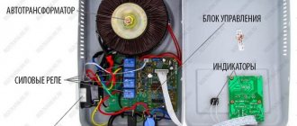
What is grounded in electrical installations?
The requirements and rules for using protective grounding are compiled into a single document that regulates and determines the standardization of the entire process - GOST. Grounding, which ensures the protection of personnel and consumers from electric shock, is carried out strictly in accordance with the requirements of the PUE and the relevant GOST. Protective grounding of electrical installations provides for the electrical connection of the metal parts of electrical installations with the ground, and in its absence - with a conductor that replaces the ground. It should also be noted that those parts of the installations that have no other protection are grounded.
Thus, the metal casings of electrical units, devices, machines, cable couplings, lamps, sockets and switches, as well as the armor of cables and wires are grounded.
Connection methods
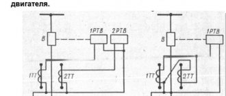
The peculiarity of the functioning of high-voltage systems is that when a line is damaged or broken, a separate wire is shorted to ground. At the same time, leakage currents are represented by impressive values. What is distinctive are the security measures that apply to such networks. They are incomparable with similar activities carried out in the end consumer chains. In networks with 6 - 35 kV, the following types of neutral grounding are used as standard:
- Direct connection with a grounding device (GD), which is installed near a high-voltage support, substation with a transformer. Such a scheme is usually called a solidly grounded neutral.
- The connection is made using special devices - compensators or arc suppression reactors.
- The process uses a grounding system, which involves connecting the described neutral point via a resistor.
- Creation of an isolated neutral bypassing the connection of the charger within the serviced facility, the protected high-voltage line.
When certain inductance values are reached, the current at the point of closure of the ground electrode used reaches zero values. A more efficient effect of such grounding with parallel induction is ensured by including a resistor. Such a device ensures the flow of active current, which is necessary for the operation of the high-voltage protective relay.
Without connecting the designated devices into the circuit, it is impossible to create effective protective functions. If an accidental breakdown of the neutral conductor occurs, operating power installations at substations will be unprotected.
It is worth mentioning another option for grounding the neutral connected to networks from 6 to 35 kV. The common point is connected to the supply circuit, which makes it possible to effectively use the ground electrode. This creates optimal conditions for the flow of active current. A significant disadvantage of the method is its high cost; for this reason, it is used only in the areas of supply substations where input voltages reach 110 kV or more.
Advantages and disadvantages of an isolated neutral
The undoubted advantage of the isolated neutral mode is that there is no need to quickly disconnect the first single-phase ground fault. In addition, a small current is generated in places of damage, provided that the current capacitance to the ground is small.
However, this mode has a number of significant disadvantages, due to which its use is significantly limited.
The main disadvantages of an isolated neutral:
- Possible arc overvoltages of an intermittent nature of a small current arc at the site of a single-phase ground fault.
- Damage can occur in many places due to insulation breakdown at other connections where arcing surges occur. For this reason, many cables, electric motors and other equipment fail at once.
- Arc surges affect insulation over a long period of time. As a result, defects gradually accumulate in it, which leads to a decrease in service life.
- All electrical equipment must be isolated for line voltage relative to ground.
- Damage locations are quite difficult to detect.
- There is a real danger of electric shock to people in the event of a prolonged ground fault.
- With single-phase faults, the correct operation of relay protection cannot always be ensured, since the value of the real fault current is completely related to the operating mode of the network, in particular, to the number of connected connections.
Thus, a large number of disadvantages cover all the advantages of this grounding mode. However, under certain conditions, this method is considered quite effective and does not contradict the requirements of the PUE.
Protecting people from electric shock in a network with a solidly grounded neutral
Now we move on to a direct explanation of why the transformer neutral is grounded and how it works.
Theoretically, for any point in the electrical network, the potential of the neutral conductor relative to the ground is zero. The consumer's re-grounding circuit makes this equality even stronger, especially if the supply substation is far away.
Electrical shock to people is possible in the following cases:
- Insulation failures inside electrical equipment when its body is energized;
- Violations of the insulation of wires and cables, when the metal structures along which they are laid become energized;
- Violation of the insulation of live parts or breakdown of electrical equipment, when potential zones are formed on the surface of the ground or floor that are dangerous for people passing by (step voltage);
- Errors during repair and operation leading to direct contact with electrical equipment components under phase voltage.
To eliminate the situations described in paragraphs 1 and 2, all housings of electrical appliances and metal structures are connected to a ground loop. At enterprises, for this purpose, a steel strip is laid along the perimeter of rooms with electrical equipment, to which all metal parts are attached. Thus, their potential is forcibly equated to the potential of the earth.
If a short circuit of phase conductors occurs to a body grounded in this way, even if the protection fails to operate, the fault current will flow through the grounding conductors to the grounding loop. The resistance relative to the ground of the body of a person who touches the emergency housing is much greater than the resistance between the ground and the housing. Therefore, a current exceeding dangerous values will not flow through the human body.
The second principle of protection is quick shutdown of emergency mode. After all, the current will not just go to the circuit, it will go towards the neutral of the transformer. A short circuit is created, the current of which is of great importance. The protective equipment will respond successfully to it: a fuse or a circuit breaker. The accident will be eliminated almost instantly, the damaged area will be switched off.
Now let's move on to point 3 and step voltage protection. It is dangerous to approach an exposed wire lying on a wet concrete floor. Life-threatening potential radiates from him in waves, like ripples on water. If your feet are placed on areas of the floor with different potentials, you may also receive an electric shock.
If such a situation is possible in a room, a potential equalization system is installed inside the floor: a metal mesh is walled up. The grid is connected to the ground loop in several places. Thus, the legs of a passer-by are shunted by the metal bars of the grid, and most of the current will flow past him.
Precautionary measures
The task and features of grounding transformers.
Now let’s look at why the transformer neutral is grounded, and the physics of how such an electrical network works.
In theoretical physics, the potential of the neutral conductor with respect to the ground should not exceed zero. Repeated grounding at the consumer's receiving device helps to achieve this value with an even higher degree of probability, especially if there is a sufficient distance to the TS.
Electric shock is possible in the following situations:
- Damage to the insulation of live parts, failure of electrical equipment. A step voltage is generated - a potential appears on the floor plane that is unsafe for a walking person;
- Damage to the insulation of electrical equipment. In this case, there may be dangerous voltage on the housing;
- Damage to the protective insulation of the cables. Here the voltage appears on the metal shelves, with the cable lines lying down;
- Violation of the work technology, which led to touching live parts under phase voltage.
It is not recommended to approach a plugged-in wire lying on a wet floor. This situation creates potential that is dangerous for humans. When trying to take a step, the legs are exposed to different potential values. Electric shock guaranteed. To avoid such a development of events, before pouring concrete, a metal frame is laid, connected to the ground loop at at least 2 points. Due to this, if a potential occurs on the floor, the legs of a walking person will be shunted, and electric shock will be avoided.
To prevent the appearance of voltage on non-current-carrying parts of the electrical system, the PUE requires grounding absolutely all metal parts located in the switchgear of transformer substations and consumers, as well as the housings of electrical appliances. In industrial workshops where there is electrical equipment (machines, production lines), a steel strip is laid around the perimeter to connect all metal-containing parts without exception. Thus, the potentials of the ground and metal parts located in the room are equalized.
If a breakdown occurs on a grounded body, the electric current will follow the path of least resistance, i.e. along the grounding conductors to the grounding loop, and not through the highly resistant human body, even if the protection does not work.
Precautions when working in a network with a solidly grounded neutral
For this reason, the current through the ground loop will be directed towards the neutral of the power transformer. This results in a short circuit with a large amount of electric current. If the specified parameter is exceeded, a protective switching device will have to react: a fuse link or a circuit breaker. Due to this, the damaged section of the circuit will be taken out of operation. Thus, rapid localization of emergency conditions is organized.
Installation of networks with a completely grounded neutral
As can be seen from Figure 2, a characteristic feature of TN type power networks is the neutral grounding. Note that in this case we are not talking about protective grounding, but about the working connection between the neutral and the grounding circuit. According to current standards, the maximum resistance of such a connection is 4 Ohms (for 0.4 kV networks). In this case, the neutral wire coming from the solidly grounded middle point must maintain its integrity, that is, not be switched and not equipped with protective devices, for example, fuses or circuit breakers.
In overhead lines up to 1 kV, used in systems with a solidly grounded neutral, neutral wires are laid on supports, like phase wires. In places where a tap is made from power lines, as well as every 200.0 meters of the main line, it is necessary to re-ground the zero lines.
Example of a TN-CS network device
If cables are routed from transformer substations to the consumer, then when using a scheme with a solidly grounded neutral, the length of such a line cannot exceed 200.0 meters. At the input switchgear, the PE bus should also be connected to the ground loop; as for the neutral wire, the need to connect it to the ground depends on the design.
PUE requirements
In the Rules, Chapter 1.7 is devoted to the standards and requirements for solidly grounded systems; we present the most significant excerpts from it:
- To connect the neutral to the ground loop, you must use a special conductor.
- When choosing a location for a grounding device, you should proceed from the minimum permissible distance between it and the neutral.
- If a reinforced concrete foundation structure is used as grounding, then it should be connected to its reinforcing base at at least 2 points, this guarantees the most effective protection.
- The resistance of the grounding conductor for a three-phase electrical network circuit of 0.4 kV is limited to 4 Ohms. In exceptional cases, this standard may be revised based on the characteristics of the soil.
- It is prohibited to install fuses, protective devices and other elements that could compromise the integrity of the conductor in a solidly grounded neutral line.
- The rules require that the grounding conductor be provided with reliable protection from mechanical damage.
- The overhead line must be equipped with redundant grounding switches; they are installed at the beginning and end of the line, on branches, and also every 200 m.
- Duplicate grounding must also be carried out at the consumer input and must be indicated in the ASU panel diagram.
- When organizing household single-phase networks from the ASU, wiring must be carried out with three wires, one of which is phase, the second is zero (N) and the third is protective (PE).
- The response speed of circuit breakers installed in single-phase networks with a solidly grounded neutral should not last longer than 0.40 seconds.
Grounding and grounding
Due to the fact that the process neutral of the transformer windings is grounded, there is confusion in the use of N and PE conductors.
We advise you to study the division of circuit breakers according to time-current characteristics
The rules for electrical installations clearly define that the process neutral - wire N - can be connected to the housings of electrical appliances only in a three-phase network. It is in this case that no current flows through it and therefore it is called a neutral conductor, and the method of connecting it is grounding.
When supplying single-phase consumers, current flows through wire N. Therefore, it should absolutely not be connected to the body of an electrical appliance. Firstly, it is dangerous due to the possibility of electric shock to people. Secondly, power will not be supplied to the consumer, since there is no electrical connection between its circuit and the body.
A similar error is connecting the protective conductor PE to the N terminal of the RCBO or RCD. If PE is connected to the input and output, then the protection will not operate. And with opposite switching, for example, wire N at the input and PE at the output, on the contrary, a constant disconnection will occur.
A solidly grounded neutral is not a guaranteed protection against electric shock to people. It only reduces the severity of the consequences. Therefore, compliance with electrical safety rules is mandatory in any case.
Solidly grounded neutral
Solidly grounded neutral - the neutral of a transformer or generator, connected to a grounding device directly or through low resistance.
Solidly grounded neutral - the neutral of a generator or transformer connected directly to a grounding device.
A solidly grounded neutral is obtained when it is connected to the ground by a system of conductors and electrodes located in the ground near the installation site of the generator or transformer. From the neutral there is a wire called zero, which is connected to the body of each energy receiver. Systems with a solidly grounded neutral are used to power most industrial and household electrical receivers.
Solidly grounded neutral - the neutral point of the winding of a transformer or generator, connected directly to the grounding device.
A solidly grounded neutral is the neutral of a transformer or generator, connected to a grounding device directly or through a high resistance.
A solidly grounded neutral is the neutral of a transformer or generator that is directly connected to a grounding device.
Since a solidly grounded neutral is a special case of an effectively grounded neutral, it has, to one degree or another, the advantages and disadvantages of an effectively grounded neutral.
With a solidly grounded neutral (solidly grounded neutral is mandatory in four-wire AC networks), grounding is carried out by connecting the metal structures of the crane and crane tracks with a grounded neutral through the neutral wire of the line feeding the crane.
With a solidly grounded neutral, the ground fault current and the current passing through a person do not depend on the value of the insulation resistance.
With a solidly grounded neutral, grounding is carried out by connecting the metal structures and rail tracks of the crane with a grounded neutral through the neutral wire of the line feeding the crane.
With a solidly grounded neutral, the task of protective grounding is to ensure, through the neutral wire (grounding), rapid automatic disconnection of the damaged area using a fuse or circuit breaker.
With a solidly grounded neutral, grounding is carried out by connecting the metal structures and rail tracks of the crane with a grounded neutral through the neutral wire of the line feeding the crane.
With a solidly grounded neutral of a network with a voltage of up to 1 kV, the conductors of the protective grounding network must have a conductivity sufficient to disconnect the protective device in the event of a single-phase short circuit. To ensure the necessary strength and durability, the cross-section of grounding conductors is standardized by the PUE.
B with a solidly grounded neutral, in which the neutral point is connected to the ground through a small active resistance.
Electrical installations with a solidly grounded neutral are widely used in industrial enterprises. This is largely explained by the advantages of solid grounding of the neutral from a safety point of view, which manifest themselves when one of the phases of the electrical installation is short-circuited to ground and when the higher voltage passes to the low side in the supply transformer.
Properties of networks with solidly grounded neutral and effectively grounded neutral
Electrical networks with a voltage of 220 kV and higher operate with a solidly grounded neutral. Networks with a voltage of 110 kV operate with an effectively grounded neutral.
Let us consider the properties of such networks.
In networks with a voltage of 220 kV and above, the neutrals of all transformers are grounded (Figure 7.4). Disconnectors are not installed in the neutral circuit of transformers of class 220 kV and above
Figure 7.4 – Network with solidly grounded neutrals
In normal operation, neutral grounding does not affect the operation of the network. The influence of the neutral grounding mode only appears in the event of a ground fault.
Consider a single-phase ground fault at point K. The grounded neutral, line and ground fault location form a closed loop through the ground. When grounding the neutrals of two transformers, as shown in Figure 7.4, there will be two closed circuits through the ground in which short-circuit currents Ik1 and Ik2 flow. At the short circuit point, the currents of all circuits are summed up and the total short circuit current flows through the fault point. The magnitude of the short-circuit current is determined by the value of the equivalent resistance of the equivalent circuit relative to the short-circuit point. In this case, the total current at the site of a single-phase short circuit in complex form is determined by the expression:
(7.1)
where Z1Σ, Z0Σ, are equivalent (total) resistances, positive and zero sequence; UФ – phase voltage.
Three-phase short circuit current.
. (7.2)
Equivalent positive and zero sequence resistances in networks of 110 kV and above can be comparable in magnitude. In this case, single-phase short circuit currents can be close in magnitude to three-phase short circuit currents. Therefore, networks of 110 kV and above are called networks with high ground fault currents. Large currents during a short circuit to ground are the main property of networks with solidly grounded and effectively grounded neutrals.
This is both an advantage and a disadvantage of such networks. Advantage: with a large short circuit current, it is relatively easy to identify the damaged line, relatively easy to determine the location of the short circuit and quickly disconnect (isolate) the damaged element.
Disadvantage: with a high short circuit current, the operation of the equipment becomes more difficult. The requirements for thermal and dynamic resistance are increasing.
110 kV networks and networks with a voltage of 220 kV and higher have one important difference: overhead lines with a voltage of 220 kV and higher are made without branches and do not have intermediate power take-offs. 110 kV overhead lines, in contrast to lines with voltages of 220 kV and higher, have numerous branches to substations of industrial enterprises. At the same time, from the 110 kV overhead line through branch substations (PS-3 in Figure 7.5), consumers geographically remote from the node substations of the power system (PS-1 and PS-2 in Figure 7.5) receive power. Up to five branch substations can be connected to one 110 kV overhead line.
Figure 7.5 – Network with effectively grounded neutral
Moreover, the number of transformers in a 110 kV network can be several times greater than in networks with a voltage of 220 kV and higher. If in a 110 kV network the neutrals of all transformers are grounded, then with a single-phase short circuit to the ground there will be several circuits for short-circuit currents. This will lead to a sharp decrease in the equivalent zero-sequence resistance Z0Σ. If the zero-sequence resistance decreases to the positive-sequence resistance and the equality Z1Σ = Z0Σ is satisfied, then, in accordance with (7.1) and (7.2), the single-phase short circuit current will be equal to the three-phase short circuit current. If the zero-sequence resistance becomes less than the positive-sequence resistance Z0Σ 1Σ, then the single-phase short circuit current in accordance with (7.1) and (7.2) will become greater than the three-phase short circuit current: This is dangerous for the thermal and dynamic stability of the network and they try to avoid this. To ensure that the single-phase short circuit current does not exceed the three-phase short circuit current, the neutrals of some transformers (T3 and T4 in Figure 7.5) are grounded. In this case, the number of parallel circuits decreases and the equivalent resistance Z0Σ increases. To make it possible to disconnect the neutral, QS disconnectors are installed in the neutral circuit. Networks in which some of the neutrals are isolated from the ground, and some are grounded, are called networks with an effectively grounded neutral.
(this is only allowed in 110 kV networks).
Neutrals are usually ungrounded at branch substations, that is, at the gas substations. Only dispatchers of the regional power system can make a decision on disconnecting the neutral at a particular gas station. The number of transformers whose neutrals should be grounded is determined by calculation.
Figure 7.5 shows vector diagrams of voltages at the point of a single-phase short circuit.
Figure 7.6 – Vector diagrams of voltages at the short-circuit point
Figure 7.5, a shows the phase voltage vectors UA, UB and UC with respect to the neutral of transformer N. In normal mode, the potential of the neutral with respect to the ground is zero. In case of a short circuit to the ground, phase A through the ground from point 3 of the ground (Figure 7.4) to the neutral of the transformer will flow a short-circuit current Ik, which lags behind the phase voltage by an angle φ. From the short-circuit current in the earth resistance between the point in the ground 3 at the fault point and the grounded neutral N, a voltage drop UЗN will appear. In this case, the phase voltages UВЗ and UСЗ of undamaged phases B and C in relation to the ground will differ from the phase voltages in relation to the neutral: UВЗ is not equal to UВ and UСЗ is not equal to UС.
The ratio of the potential difference between the undamaged phase and the ground during a faulty fault to the potential difference between the phase and the ground at this point before the fault is called the closure coefficient (PUE clause 1.2.4). For an electrical network with an effectively grounded neutral, the earth fault coefficient should not exceed 1.4 ( kз ≤ 1.4
). The number of transformers with an ungrounded neutral is selected so that the following condition is satisfied:
. (7.2)
If the disconnector in the neutral is disconnected, then in the event of a single-phase short circuit, phase voltage may appear on the neutral isolated from the ground. In normal operation, the voltage at the transformer neutral with respect to ground is zero. Therefore, to reduce the cost of the transformer, the insulation of the neutrals of transformers of the 110 kV class is usually weakened. The phase voltage on the neutral in relation to the ground for weakened neutral insulation is dangerous and can cause its breakdown. Schemes for protecting the transformer neutral from overvoltage are shown in Figure 7.7. As FV protective equipment, arresters (Figure 7.7, a) or surge suppressors (Figure 7.7, b) are used. To make it possible to ground the neutral (if necessary), a QS disconnector is installed parallel to the arrester. The rated voltage of the arrester is selected to be a class lower than the rated mains voltage. For example, if the network voltage is 110 kV, then the arrester is set to 55 kV. To do this, two arresters of 20 and 35 kV are connected in series.
Figure 7.7 – Transformer neutral protection circuits
Classification of networks with solidly grounded neutral
A modern power supply system has a standard marking where, in addition to the working neutral conductor, there is also a protective one, which determines the degree of protection.
- L - phase conductor;
- N—working zero;
- PE - protective neutral conductor;
- PEN - the working and neutral conductors are made of one wire.
There are several subsystems in circuits with an energy source that has a solidly grounded neutral:
- TN-C. With this system, the neutral and protective conductor from the substation are organized by one conductor; near the receiver of a single-phase circuit, its housing (or other elements to be grounded) is connected to this combined conductor - this is called grounding. This is an outdated system, it was used in old houses during the USSR, but now it is not used for household consumers, as it is unsafe. Such a system has a significant drawback, since if the PEN conductor breaks on the path from the supply transformer to the power receiver, a dangerous potential appears on the grounded equipment housings. Used only to protect industrial consumers (discussed below in the next section).
- TN-S. Has a greater percentage of safety during emergency situations. This is achieved by separating the protective and working conductors along the entire length of the supply line, from the transformer to the electrical distribution panel (to the end consumer). However, due to the fact that it is necessary to use cable products with five cores, which greatly increases the cost of installation and the budget for organizing power supply to the consumer, this system is not always used.
- TN-CS. This grounding system is the most common in our time. With this system, the neutral and protective conductors along the entire length of the line are combined into one combined conductor PEN. At the entrance to the building, this conductor is divided into protective PE and zero N, which are then distributed to consumers (apartments). With this system, if the PEN conductor burns out to the separation point, a dangerous potential will appear on the grounded housings of electrical appliances. To prevent this, repeated grounding of the PEN conductor is made along the entire length of the line and at the entrance to the building and increased requirements are imposed on the mechanical protection of this conductor.
- TT. This grounding system is practiced if the TN-CS system line is in unsatisfactory technical condition and the protective grounding provided in it does not provide sufficient safety. This grounding system provides for the installation of an individual grounding loop at the consumer, while the PEN conductor of the electrical network is used only as the neutral wire N.
Types of TN systems
How electrical installations are divided according to electrical safety conditions
There are several types of such systems:
- TN-C. All metal parts and housings of electrical appliances are connected to the neutral conductor connected to the neutral. It is called combined. The generally accepted designation is PEN. The old scheme was widespread in the Soviet Union. Unsafe. For ordinary consumers it is currently not used, because Grounding the housings of household electrical appliances is difficult to do. It has a serious drawback: if the PEN conductor breaks, an unsafe potential appears on neutralized electrical appliances;
Important! Grounding is an electrical connection between ungrounded housings, which are not under voltage in the normal state, and the neutral wire of the transformer.
Types of TN circuits
- TN-S. Safety in the event of an emergency is significantly increased. Here, the functions of the working and protective conductor are separated along the entire length, right up to the consumer switchgear. However, the use of a five-wire cable is required, which slightly increases the cost of laying a cable line;
- TN-CS. The most common grounding system in modern electrical engineering. The PEN conductor is divided into N and PE directly in the consumer's main switchboard. If the PEN conductor is damaged to the point of separation, voltage may appear on the metal structures, just as in the case of the TN-C system. To prevent this from happening, repeated grounding of the PEN conductor is made along the entire length of the cable line;
- TT. Provides for the creation of an individual grounding device for the consumer. Rarely seen.
This mode of operation of the grounded neutral protects against electric shock. In the event of an accident, the potential is equalized, so touching metal structures ceases to be dangerous.
Invite to tender
If you have a tender and need more participants:
Select from the list the type of work that interests youIndustrial safety auditIdentification and classification of hazardous production facilities, obtaining a license to operate hazardous production facilitiesDevelopment of plans, action plans, documentation related to the readiness of enterprises for civil emergency situations and fire safetyInspection and examination of the industrial safety of buildings and structuresWork on lifting structuresWork on boiler inspection and power equipment facilitiesWorks at gas supervision facilities Work at chemical and petrochemical facilities Work at facilities related to the transportation of hazardous substances Work at production facilities for the storage and processing of plant raw materials Work at metallurgical foundries Work at mining plants Conformity assessment of elevators, technical examination of elevators Development of a safety justification for a hazardous production facility Development of documentation for an industrial safety management system Development of industrial safety declarations securityWork at the facilities of the Ministry of Defense (special purpose production of military units) and the facilities of the Federal Penitentiary Service of Russia (special purpose organization of correctional institutions) Design Repair and installation work Repair of automobile lifting equipment Electrical repair and electrical measuring work Development and production of safety devices for industrial facilities Development and production of non-standard metal products and equipment Non-state examination of design documentation (engineering surveys) Pre-certification training according to safety rules and standards Vocational training (blue-collar professions) Training in labor protection, fire safety and electrical safety, heat power engineering Special assessment of working conditions (SOUT) (until 2014 certification of workplaces)Accreditation and certification in the industrial safety examination systemCertification of equipment, declaration of conformityEnergy auditDevelopment of heat supply and water supply schemesOther workAdvanced training, professional retrainingInspection of shelvingCopy the link to your tender into this field, to do this, go to the browser, open your site, highlight and copy the address line, then paste into this field. If it doesn’t work out, just write the tender number and the name of the site. personal data
We recommend studying Electrical Engineering for Beginners
Grounding and grounding
7.3.132. Explosive zones of any class indoors and outdoor explosive installations are subject to the requirements given in 1.7.38 regarding the admissibility of using a solidly grounded or insulated neutral in electrical installations up to 1 kV. With an isolated neutral, automatic control of the network insulation must be provided with an effect on the signal and monitoring of the serviceability of the breakdown fuse.
7.3.133. In hazardous areas of classes BI, B-Ia and B-II, it is recommended to use protective shutdown (see Chapter 1.7). In hazardous areas of any class, potential equalization must be performed in accordance with 1.7.47.
7.3.134. In explosive zones of any class, the following must also be grounded (grounded):
a) as amended by 1.7.33 - electrical installations at all AC and DC voltages;
b) electrical equipment installed on neutralized (grounded) metal structures, which in accordance with 1.7.48, paragraph 1 in non-explosive areas are allowed not to be neutralized (not grounded). This requirement does not apply to electrical equipment installed inside neutralized (grounded) cabinets and control panels.
Conductors specially designed for this purpose must be used as neutral protective (grounding) conductors.
7.3.135. In electrical installations up to 1 kV with a solidly grounded neutral, grounding of electrical equipment must be carried out:
a) in power networks in explosive areas of any class of a separate residential cable or wire;
b) in lighting networks in explosive zones of any class, except for class BI, - in the area from the luminaire to the nearest branch box - with a separate conductor connected to the neutral working conductor in the branch box;
c) in lighting networks in an explosive zone of class BI - with a separate conductor laid from the luminaire to the nearest group panel;
d) on the network section from the switchgear and transformer substations located outside the explosive zone to the switchboard, assembly, distribution point, etc., also located outside the explosive zone, from which power is supplied to electrical receivers located in explosive zones of any class, is allowed as For the neutral protective conductor, use the aluminum sheath of the power cables.
7.3.136. Neutral protective conductors in all parts of the network must be laid in common shells, pipes, boxes, bundles with phase conductors.
7.3.137. In electrical installations up to 1 kV and higher with an insulated neutral, grounding conductors can be laid either in a common shell with phase conductors or separately from them.
Grounding lines must be connected to grounding conductors in two or more different places and, if possible, from opposite ends of the room.
7.3.138. The use of metal building structures, industrial structures, steel electrical wiring pipes, metal cable sheaths, etc. as neutral protective (grounding) conductors is allowed only as an additional measure.
7.3.139. In electrical installations up to 1 kV with a solidly grounded neutral, in order to ensure automatic shutdown of the emergency section, the conductivity of the neutral protective conductors must be selected such that, in the event of a short circuit to the housing or neutral protective conductor, a short-circuit current occurs that is at least 4 times greater than the rated current of the fuse link of the nearest fuse and at least 6 times the current of the circuit breaker release, which has an inverse current characteristic.
When protecting networks with automatic circuit breakers that have only an electromagnetic release (without a time delay), you should be guided by the requirements regarding the short-circuit current multiplicity and given in 1.7.79.
7.3.140. A calculated check of the impedance of the phase-zero loop in electrical installations with voltages up to 1 kV with a solidly grounded neutral must be provided for all electrical receivers located in explosive zones of classes BI and B-II, and selectively (but not less than 10% of the total number) for electrical receivers located in explosive zones of classes B-Ia, B-Ib, B-Ig and BIIa and having the highest phase-zero loop resistance.
7.3.141. Passages of specially laid neutral protective (grounding) conductors through the walls of rooms with explosive zones must be made in pipe sections or in openings. The openings of pipes and openings must be sealed with non-combustible materials. The connection of neutral protective (grounding) conductors in passage areas is not allowed.
Features of networks with isolated and solidly grounded neutral
Features of networks with isolated and solidly grounded neutral
Electrical networks of industrial enterprises can operate both with a transformer neutral isolated from the ground, and with a transformer neutral connected to the ground tightly or through low resistance. [...]
A network with an isolated neutral operates effectively only if it has a reliable device for continuous monitoring of insulation with shutdown of the network when the insulation resistance decreases below a predetermined limit, as well as under the condition of continuous monitoring of the integrity of the breakdown fuse. [...]
Currently, four-wire networks with a solidly grounded neutral are most widespread in industrial enterprises, allowing the use of two operating voltages - linear and phase. The use of a simpler and more reliable system of combined power supply of power and lighting electrical receivers from common transformers reduces the cost of the installation as a whole due to the installation of fewer transformers, reduction of conductor material, etc. [...]
From a safety point of view, networks with a solidly grounded neutral, despite the existing disadvantages, are not more dangerous than networks with an isolated neutral. The presence of significant capacitance relative to the ground of branched cable networks with an isolated neutral essentially negates the known advantages of these networks. [...]
The main protective measures to ensure electrical safety are: in systems with an isolated neutral - protective grounding, and in networks with a solidly grounded neutral - grounding. [...]
When grounding, all metal non-current-carrying parts that may be energized are electrically connected to the neutral protective conductor. Thanks to this connection, any short circuit to the housing or metal structure turns into a single-phase short circuit, the nearest fuse burns out or the circuit breaker is triggered and the damaged area is switched off. [...]
The protective effect of grounding depends on the resistance of the grounding device, the reliability of the circuit between the grounding conductors and the grounded elements. For the speed and reliability of disconnecting a damaged section of an electrical installation in networks with a solidly grounded neutral, the resistance of the phase conductor - neutral protective conductor circuit is essential. All these factors depend on the accuracy of the calculation of the grounding device, the correctness of its installation and operation. Therefore, before commissioning newly installed electrical installations, as well as periodically during their operation, a thorough test of grounding devices is carried out. [...]
Return to contents
ru-safety.info
Equipment and tools for measuring ground resistance
The main instrument used to measure resistance to spreading currents is the IS-10 grounding meter. This device operates in five measurement ranges, which explains its wide application. The minimum range is 0.01 to 9.99 ohms, followed by 0.1 to 99.9 ohms, 1 to 999 ohms, 0.01 to 9.99 kohms. The maximum resistance determined by this device is in the range from 1 to 999 mOhm. In combination with the measuring device, remote current and potential electrodes are used.
It should be noted that the grounding measuring circuit is assembled according to strict rules - the connecting conductors of the device, first of all, to the current and potential electrodes, then to the device and lastly to the ground electrode.
What it is
The definition of “isolated neutral” is given in Chapter 1.7. PUE, in paragraph 1.7.6. and GOST R 12.1.009-2009. Where it is said that the neutral of a transformer or generator is called isolated when it is not connected to a grounding device at all, or when it is connected through protection, measurement, and alarm devices.
The neutral is the point at which the windings of transformers or generators are connected when switched on in a star configuration.
There is a misconception among electricians that the abbreviated name for an insulated neutral is an IT system, according to the classification of clause 1.7.3. Which is not entirely true. The same paragraph states that the designations TN-C/CS/S, TT and IT are accepted for networks and electrical installations with voltages up to 1 kV.
In the same chapter 1.7 of the PUE there is paragraph 1.7.2. where it is said that with regard to electrical safety measures, electrical installations are divided into 4 types - isolated or solidly grounded up to 1 kV and above 1 kV.
Thus, there are some differences in the safety and application of such a network in different voltage classes, and calling a 10 kV line with an isolated neutral “IT system” is at least incorrect. Although schematically it’s almost the same.
We advise you to study the Power Line Security Zone
What is the difference between an isolated neutral and a solidly grounded one? Networks with isolated neutral
PRINCIPLE OF OPERATION AND OPERATION OF INDUSTRIAL ELECTRICAL INSTALLATIONS OF AC AND DC CURRENT
Electrical installations are a set of machines, apparatus, lines and auxiliary equipment (together with the structures and premises in which they are installed) intended for the production, transformation, transformation, transmission, distribution of electrical energy and its conversion into another type of energy .
The electrical network is a set of electrical installations used for the transmission and distribution of electrical energy, consisting of switchgear substations, conductors, overhead and cable power lines. The operation of a 3-phase alternating current electrical installation with an industrial frequency of 50 Hz is largely determined by the operating mode of the neutrals of generators or transformers. There are mainly two types of central systems in practice, an insulated neutral and a grounded neutral.
An isolated neutral is a generator or transformer neutral that is not connected to a grounding device or is connected through devices with high electrical resistance (alarm devices, protection devices, arc suppression reactors). A grounded neutral is a generator or transformer neutral connected directly to a grounding device or through low electrical resistance. The operating mode of the neutrals largely determines the level of insulation of electrical installations, the choice of switching equipment, the magnitude of overvoltages and methods of limiting them, the magnitude of currents of single-phase short circuits to the ground (case), operating conditions of relay protection, etc.
An earth fault is an accidental connection of live parts of an electrical installation with structural parts that are not isolated from the ground, or directly with the ground.
A short-circuit to the frame is an accidental connection of energized parts of an electrical installation with their structural parts that are not normally energized.
Electrical installations in which the ground fault current (frame) does not exceed 500 A are considered electrical installations with low ground fault currents. Electrical installations with a ground fault current (frame) of more than 500 A are considered electrical installations with high ground fault currents.
Electrical installations with voltages up to and above 1000 V with an isolated generator or transformer neutral operate with low single-phase ground fault currents (033). These are 3-phase electrical installations with a linear voltage of 220-380-660 V and 3-35 kV, respectively.
Electrical installations with a grounded neutral (effectively grounded neutral) with a voltage of 110 kV and higher operate with large ground fault currents. 4 wire 3-phase electrical networks with voltages up to 1000 V also work with a grounded neutral, in which currents 033 may not have large values. These are electrical installations with voltages of 220/127 V, 380/220 V, 660/380 V.
Single-phase faults to ground (frame) account for up to 75% of all types of damage in electrical installations.
The operating mode of the neutral also significantly affects the electrical safety conditions of people. In electrical installations with an insulated and grounded neutral, various electrical protective measures are used, which will be discussed below. According to electrical safety conditions, electrical installations are divided into electrical installations with voltage up to 1000 V, turn on
buildys.ru
Explanation for dummies
The step-down substation in which the transformer is installed has its own ground loop. It is interconnected by steel tires and rods into one grounding circuit. A cable containing four cores is laid to consumers in the electrical panel from the substation:
- three of them are phases;
- one ground connected near the transformer to the ground loop.
If the consumer needs power from a three-phase 380 Volt circuit, then it must be connected to these three wires. In a single-phase 220 V network, power will be supplied from the neutral wire and from one of the phases. The protection of people in single-phase and three-phase circuits, if there is no grounding system, should be carried out using special residual current devices (RCDs), which are triggered by a small leakage to zero, while reliably disconnecting the consumer from the network.
Requirements for grounding devices
All devices used for grounding must comply with state-approved standards, building codes and PUE. Their task is to ensure the safety of people, the protection of electrical installations and their operating modes.
In no case is it allowed to connect several parts of an electrical installation in series with grounding conductors - each part must correspond to only one grounding cable, having a cross-sectional diameter no smaller than that specified in the PUE. Grounding conductors placed openly are protected from exposure to aggressive environments by painting them black.
The technical condition of grounding devices and testing of grounding is carried out by inspection with the naked eye of the visible part of the device, inspection with partial opening of the soil and measurement of the parameters of the grounding device. The visible part of the device is inspected once every six months.
Grounding devices
According to the PUE, to protect people from dangerous voltages, a grounding circuit is used, mounted by electrically connecting parts of the installation made of conductive materials and isolated from live parts with a ground electrode. In turn, the ground electrode is a conductor made of metal that has good electrical conductivity and a large area of contact with the soil. All together - the grounding conductor and the wires electrically connecting it to parts of electrical installations constitute a grounding device.
Depending on the type of current used in electrical installations up to 1000 V, grounding schemes with a solidly grounded neutral or isolated (alternating current), solidly grounded or isolated midpoint (direct current) are used. The neutral of a power source (generator or transformer) is called solidly grounded if it is connected directly to a grounding device, and the neutral that is not connected to it or is connected through devices with high resistance is considered isolated.
Isolated Neutral
The isolated neutral has found quite wide application in domestic energy systems. This grounding method is used for generators or transformers. In this case, their neutral points are not connected to the ground loop. In distribution networks of 6-10 kilovolts, there may be no neutral point at all, since the connection of transformer windings is carried out using the triangle method.
In accordance with the PUE, the isolated neutral mode can be limited by capacitive current, which is the current of a single-phase fault to the ground of the network. Its compensation using arc suppression reactors is provided at the following values:
- Current over 30 amperes, voltage 3-6 kilovolts;
- Current over 20 amperes, voltage 10 kilovolts;
- Current over 15 amperes, voltage 15-20 kilovolts;
- Current over 10 amperes, voltage 3-20 kilovolts, with metal and reinforced concrete supports of overhead power lines
- All electrical networks with a voltage of 35 kilovolts.
- In generator-transformer blocks with a current of 5 amperes and a generator voltage of 6-20 kilovolts.
Ground fault current compensation can be replaced by resistive grounding of the neutral using a resistor. In this case, the relay protection algorithm will be changed. For the first time, grounding in the isolated neutral mode was used in electrical installations with an average voltage value.
Differences between grounding and grounding
Grounding and grounding methods have different protective effects. Grounding ensures instantaneous operation of circuit breakers when a phase is shorted to the body. In this case, the connected consumers of electricity, for example, machines, transformers, are de-energized.
But this does not save a person from the effects of leakage current, and if the neutral conductor breaks, voltage will appear on the housings of electrical equipment. In connection with this, zeroing in its pure form is not used.
At the same time, in electrical equipment with a four-wire network with a solidly grounded neutral and a neutral wire with a voltage of up to 1000V, grounding is the main means of protection.
The implementation of grounding and grounding circuits has a number of differences. One of the main ones is that for grounding it is necessary to use cables with a separate core. The cross-section of PE conductors may be smaller than the cross-section of phase conductors, and their insulation is always yellow-green.
One of the main advantages when implementing grounding is the use of cheaper cable. The advantages of grounding are that it always works and does not require frequent monitoring of the quality of the connection; once a year is enough.
Connecting zero to ground (zeroing) in a private house or apartment is not only not necessary, but can also be unsafe. If the neutral wire burns out or breaks in the floor panel, then household devices operating on 220 V will receive a much higher voltage, which will lead to their failure, and dangerous voltage will appear on their cases.
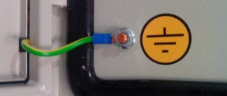
By “ground” we mean a conductor connected to the housings of electrical appliances and the grounding contacts of sockets.
To ensure the greatest safety, we can recommend a grounding and grounding device at the same time. For this purpose, the TN-CS system is implemented - grounding and zero separation at the entrance to the house, in the input common house electrical panel of the ASU.
Determination of an effectively grounded neutral
EZN is used in high-voltage networks of 110 kV and more. In the event of a phase-to-ground fault, it is a single-phase short circuit.
It is accompanied by significant currents at the site of damage, as a result of which the protection system is triggered and the voltage is cut off. Let's define what it is.
An effectively grounded neutral is a grounded neutral in three-phase voltage networks above 1000 V whose earth fault ratio is ≤ 1.4.
The figure below shows the EZN diagram:
This means that in the event of a single-phase ground fault, the voltage of other, undamaged phases will increase by an amount not exceeding 1.4.
And it is calculated using the formula below:
This is of great importance for high-voltage networks. Because with such a circuit, the voltage of undamaged phases does not significantly exceed the nominal one. This means that there is no need to increase the isolation of networks and equipment.
Operating networks with EZN will be much cheaper. It should be borne in mind that savings increase as the line voltage increases.
Operating principle of networks with solidly grounded neutral
Now we will consider in detail the purpose for which the neutral is grounded and how such an implementation ensures the proper level of electrical safety. To do this, we list the circumstances that can lead to electric shock:
- Direct contact with live elements. In this case, no grounding will help. It is necessary to limit access to such areas and be careful when approaching them.
- Formation of zones with step voltage as a result of accidents on overhead lines or other types of electrical equipment.
- Damage to the internal insulation can lead to a “breakdown” on the electrical installation body, that is, life-threatening voltage appears on it.
- As a result of a violation of the electrical insulation of current-carrying lines, cable channels, ducts and other metal structures used for routing may become energized.
Ideally, the potential difference between neutral and ground should tend to zero. Connection to the grounding circuit at the consumer input significantly contributes to the fulfillment of this condition in cases where the transformer substation is located at a considerable distance. With proper grounding, this feature can save a human life in at least the last two cases from the above list.
To avoid the harmful effects of electric current, it is necessary to ground the housings of electrical appliances, as well as other metal parts of electrical installations in buildings. This will lead to a phase-to-ground short circuit during a breakdown. As a result, there will be an automatic shutdown of the power supply to the electrical receivers, caused by the operation of the short-circuit current protection device.
Even if the protection does not work and someone touches the metal element, current will still flow through the grounding conductor, since there will be less resistance in this circuit.
Movement of current during a short circuit to the housing
Speaking about the principle of operation of grounded neutral protection, one cannot fail to note the quick exit to emergency mode when one of the phase wires is shorted to the PEN bus. In essence, this is a short circuit to the neutral, the consequence of which is a sharp increase in current, leading to a protective shutdown of the power plant or the problem section of the circuit.
Under certain conditions, it is even possible to organize protection against the formation of dangerous zones with step voltage. To do this, a metal network connected to a common grounding circuit is laid on the floor in a potentially hazardous room (if necessary, embedded in concrete).
Differences between a solidly grounded neutral and an isolated one
To explain the difference, it is necessary to briefly talk about the main features of an insulated neutral; an example of such a design is given below.
Rice. 6. Electrical installation with isolated neutral
As can be seen from the figure, with this method, the neutral is isolated from the grounding loop (in the case of a “triangle” connection of the windings, it is completely absent), therefore, the open conductive parts (hereinafter referred to as OPC) of electrical installations are grounded regardless of the network. The main advantage of such a system is that during the first single-phase fault there is no need to perform a protective shutdown. This is a definite plus for high-voltage lines, since it ensures higher reliability of power supply. Unfortunately, this grounding mode does not satisfy the electrical safety requirements for end-user networks.
The low level of electrical safety is the main, but not the only, disadvantage of an insulated neutral; a complete list of them, as well as other features of this power supply scheme, can be found on our website.