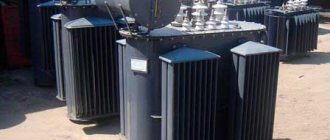
Tire arc protection
Performed in 6-10 kV switchgear chambers to protect busbars and busbars. Designed for devices with completely enclosed live parts. The work is carried out in two directions:
Device Duga-BC – protection against arc faults
Principles of construction of arc-fiber optic systems of remote sensing:
Features of constructing circuits:
Fiber optic remote sensing
Based on recording light flashes from an electric arc. The devices contain fiber optic sensors.
Location of protection in switchgear:
The electric arc is registered in all elements of the system simultaneously. Switches turn off when two factors are present:
There are two types of sensors:
Fiber optic arc fault protection
Protection benefits:
Photothyristor ZDZ
Photothyristors, which react to the brightness of light, are used to detect the phenomenon.
Photothyristors are used to protect against arc faults
Valve type protection
Allows you to protect electrical equipment from arc short circuits. It is based on the physical processes that occur during an arc fault: flashes of light, an increase in air pressure inside the switchgear chamber. This PDZ uses unloading valves with limit switches as sensors. ZDZ is installed in the camera compartments.
Why are electric arc short circuits dangerous? An electric arc for 1 second can cause equipment burnout. Cases have been recorded where short circuits led to burnout of a section of chambers.
Arc protection membrane
The action is based on the ability of the membrane switch to record changes in the electric arc pressure.
Compound:
The principle of operation is that a tube is connected to the switchgear cells. All tubes are connected to each other and combined with a switch.
Scheme of valve arc protection in switchgear 6(10) kV
In this article I will consider the valve arc protection circuit in 6(10) kV switchgear. In this case, arc protection is implemented on the limit switches of the stall pressure relief valves installed in the compartments: connections, withdrawable element (D.E.) and busbars.
Phase currents are monitored at the input switch and at higher relay protection. This is necessary due to the fact that when a short circuit occurs in the input switch cell, the current transformers may be shunted by an arc, or their secondary circuits may be damaged.
Contacts S7S, S7W, S7P are shown in the closed exhaust valve position.
Fig. 1 – Arc protection valve section 1
Fig. 2 – Arc protection valve 2 sections
The operating logic of arc protection is as follows:
In outgoing line cabinets there are 1(2) sections:
When an arc fault occurs in the busbar compartments or in the draw-out element compartment, the corresponding limit switches S7S, S7W are triggered and a command is issued via the ED1 bus to turn off the input switch of its section and the sectional switch, regardless of whether it is turned on or not.
When an arc fault occurs in the connection compartment, limit switch S7P is triggered and relay KL1 is activated, which gives the command to turn off only the switch of this connection.
In TN1(2) cabinets:
When an arc fault occurs in the compartments: connections, withdrawable element or busbars, the corresponding limit switches are triggered and a command is received through the ED1 bus to turn off the input switch of this section and the sectional switch.
In cabinets BB1(2):
When an arc fault occurs in the busbar compartments or in the draw-out element compartment, limit switches S7S and S7W are triggered, respectively, relay KL1 is triggered, which turns off the circuit breaker of this section and a command is given to turn off the CB.
When an arc fault occurs in the connection compartment, the limit switch S7P is triggered; this signal is output to the terminal block of external circuits to disconnect the upstream circuit breaker, for example a 110 kV circuit breaker.
In the SV closet:
When an arc fault occurs in the busbar compartment, the limit switch S7S is triggered, and a command is received through the ED1 bus to turn off the input switch of this section, relay KL1 turns off the CB.
When an arc fault occurs in the draw-out element compartment, limit switches S7W are triggered and commands are received through the ED1(2) bus to turn off the input switches of sections 1 and 2, relay KL1 turns off the CB.
When an arc fault occurs in the connection compartment, the limit switch S7P is triggered and a command is received through the ED2 bus to turn off the input switch of section 2, relay KL2 turns off the CB.
In the CP cabinet:
When an arc fault occurs in the sections of the busbars, draw-out element and connections, the corresponding limit switches are triggered and a signal is received through the ED2 bus to turn off the input switch of section 2 and CB.
You can also see valve arc protection circuits together with fiber-optic sensors or photothyristor sensors; this joint use of valves and sensors increases the reliability of emergency protection. These sensors are installed in each compartment, in parallel with the valve arc protection limit switches.
All the best! See you again on the Raschet.info website.
Operating principle of arc protection
6.1.1 The principle of operation of arc protection is based on tilting the covers of the arc protection valves against excess pressure that occurs during a short circuit in the limited space of the compartments of 10 kV switchgear cells and the operation of the limit switches installed on them.
6.1.2 On 10 kV switchgear cells of outgoing lines: inputs No. 1 and No. 2, TS, and DG, arc protection valves are installed above the cable compartment and above the circuit breaker compartment.
At the ends of the 10 kV switchgear sections, arc arresters are mounted, equipped with arc protection valves, which serve to protect the busbars from damage when an electric arc occurs that moves along the arc arrester busbars.
6.1.3 On the front panel of the instrument compartment of all 10 kV switchgear cells there are installed: an arc protection switch and an LED indicating the operation of the arc protection.
On the front panel of the instrument compartment of the sectional switch there are two arc protection switches /I and II sections of 10 kV switchgear/, an LED indicating the arc protection has been activated, and an arc protection release button.
The arc switch has two positions “on” and “off” and is used to disconnect the operational circuits of the arc protection of the cell from the arc protection of the bus section of the 10 kV switchgear.
In the “On” position, when arc protection is triggered at any connection, which is accompanied by a voltage drop, the switches of all connections are turned off, including sectional switch No. 1, if it was turned on.
If the arc protection switch of any cell is set to the “Off” position, then when the arc protection on this cell is triggered, only the circuit breaker of this cell will be disconnected, and when the arc protection of the 10 kV switchgear section is triggered to disconnect all connections, the circuit breaker of this cell will not turn off.
6.1.4 When the limit switch of the arc protection valve of the withdrawable element of any 10 kV switchgear cell is triggered, which is accompanied by a voltage drop on the 10 kV switchgear section, a command is sent through the arc protection switch to turn off all switches of the 10 kV switchgear and sectional switch No. 1, if it is turned on. At the same time, the indicator LED “Arc protection” installed on the front panel of the instrument compartment of this cell lights up and the “Arc protection” display of the corresponding section of the 10 kV switchgear busbars on the power plant control panel lights up.
6.1.5 When the limit switch of the arc protection valve installed on the arc arrester of section I or II of the 10 kV switchgear busbars is triggered, which is accompanied by a voltage drop, all switches of the corresponding section of the 10 kV busbars are turned off and sectional switch No. 1 is turned off, if it was turned on. In this case, the “Arc protection” display of the corresponding section on the substation control panel will light up.
Operating principle of various arc protection devices
An arc flash protection relay is a device used to reduce damage to equipment and increase personnel safety. The arc protection device detects an arc in the switchgear. When a fault is detected, the arc protection relay trips the breaker. The arc protection device works much faster than conventional protection systems (MTZ, TO, etc.).
Arc protection with arc arresters and relief valves. To protect the busbar compartment, arc arresters (AC) are installed at the ends of the switchgear section. When two sections of switchgear are placed in a single row, arc arresters are installed between the sections. When the arc occurs in the busbar compartment of the cabinet, the arc moves (without leaving any traces) along the busbars away from the power source. Having reached the end cabinet of the section, the arc enters the arc arrester. An unloading valve with a limit switch is installed on the roof of the remote control. The valve is thrown back under the influence of excess pressure of gases formed during the combustion of an electric arc, and the limit switch is triggered, giving a signal to turn off the input switch. However, for arc protection, the use of a valve in the cell significantly degrades its reliability. Valve arc protection as a mechanical device reacts not to the arc, but to the consequences of the arc, and will operate when the gas pressure reaches sufficient to trigger, therefore it has certain disadvantages: insufficient sensitivity and a significant response time.
Arc protection using photothyristors . In the switchgear section, arc protection photothyristors are installed two at a time on one bracket in the linear (cable) compartment, in the circuit breaker compartment (voltage transformer, etc.) and in the busbar compartment, depending on the switchgear design used. A photothyristor is a thyristor that is transferred to a high-conductivity state by light exposure.
The following radiation sources are suitable for controlling a photothyristor: electric incandescent lamps, pulsed gas-discharge lamps, LEDs, quantum generators, etc.
Photothyristors are installed in such a way that they can see the protected compartment. The action of photothyristors in various compartments, except for the busbar compartment, is carried out to disconnect their own circuit breaker.
To protect the busbar compartment, photothyristors are installed starting from the second cabinet, then through two cabinets on the third. When a short circuit occurs in the busbar compartment, photothyristors send a signal through the arc protection busbars to turn off the input or sectional circuit breaker. All photothyristors are connected to the arc protection busbars in parallel.
Protection based on fiber-optic sensors Fiber-optic sensors (FOS), installed in the compartments of high-voltage cabinets and having an almost circular radiation pattern, detect a light flash from an electric arc and transmit it via an optical fiber to the light detection unit of the device. At the same time, the arc protection device generates a signal to disconnect high voltage from the switchgear, thereby protecting the equipment from destruction.
Date added: 2017-04-05; views: 3327; ORDER A WORK WRITING
Find out more:
Regulatory requirements
It should be noted that the requirements and testing methods for arc resistance of switchgear equipment elements, requirements for speed and type of arc protection are not regulated today. In existing directives (Orders of RAO UES of Russia dated July 1, 1998 N 120 “On measures to improve the explosion and fire safety of energy facilities” and dated March 29, 2001 N 142 “On priority measures to improve the reliability of operation of RAO UES of Russia”) and regulatory (“ Rules for the technical operation of power plants and networks", 15th edition, clause 5.4.19) documents there are only requirements for the need for high-speed protection against arc short circuits inside switchgear cabinets.
As a result, we can formulate the following basic requirement for the protection of switchgear cells from arc faults:
The total time to eliminate a short circuit should not exceed 60 ms.
Part 8
Globally, an average of 5-6 people are admitted to burn centers every day with severe arc burns.
And 2-3 people die from electric shock. In addition to the direct impact on humans, the high temperature of the arc can serve as a source of energy to ignite materials and, as a result, cause a fire.
In this article we will analyze the principles of calculating the energy of an electric arc and talk about measures to ensure the safety of workers, including through the correct selection of personal protective equipment.
Protective clothing used to protect against the thermal component when exposed to an electric arc is described in GOST R 12.4.234-2012 Occupational Safety Standards System (OSSS). Special clothing to protect against thermal risks of electric arcs. General technical requirements and test methods.
Heat-resistant workwear consists of a suit: a jacket (or shirt) and trousers (or overalls) or overalls.
Pictogram “Work under voltage - Special clothing for protection against thermal risks of an electric arc”:
Just in case, let's clarify again. This is heat-resistant protective clothing that protects against the temperature of an electric arc. Not for protection against electric shock or for protection against metal splashes during welding operations.
The need for arc protection is caused by the imperfection of current
Despite the requirements of paragraphs of the PUE clause 3.3.31, clause 3.3.42 on the use of automatic reclosure of busbars and automatic transfer switches after the elimination of short circuits inside the switchgear compartments, today design organizations and operating enterprises reasonably doubt the need to fulfill these requirements and prefer blocking the automatic reclosure of busbars and automatic transfer switches during when the switchgear arc protection is triggered. This decision is justified by the negative experience of operating organizations in using automatic reclosure of medium-voltage busbars. Is this approach justified? Do existing protection solutions ensure that arc faults are disconnected within a time period during which no critical damage occurs inside the switchgear? Current step protections cannot be used as high-speed protection against arc faults due to the large time delays at the supply connections (usually more than 0.5 s). In order to reduce the operating time of current protection at supply connections, logical bus protection (LBP) is used, the operating principle of which is based on the transmission of blocking signals from protection devices for outgoing connections. However, in this case, the protection response time exceeds the permissible value. The LZH time delay is usually at least 100ms.
LZSH has a number of disadvantages:
Thus, LZSh also cannot be used as high-speed switchgear protection against arc faults .
Electrical Arc Protection Standards
Most countries have legislation stating that PPE must be used whenever health and safety hazards cannot be controlled by other means. Although legislation provides guidance on electrical safety measures, each industry has its own hazards and therefore PPE requirements may vary. To reliably ensure electrical safety in the workplace, it is necessary to develop requirements for each type of work. For example, normal work clothing will not be sufficient when performing electrical work where there is a risk of exposure to an electric arc. The following is a summary of the legal requirements in the two major regions where arc exposure standards apply.
In the United States, the primary government regulation is the Occupational Health and Safety Act of 1970, which can be found at 29 (Labor) US Code, Chapter 15 (Occupational Health and Safety), and provides a general duty on employers and employees. comply with this law. There is also OSHA regulation 29 CFR 1910.132 (General PPE Requirements), which provides a general requirement to ensure safety and provide employees with proper training and PPE when their health is at risk.
In Europe, PPE legislation consists of two parts. One part defines the responsibilities of employers and workers, and the other defines the sale of PPE in the EU.
The EU PPE User Directives (89/656) and relevant national PPE legislation (e.g. the Personal Protective Equipment at Work Regulations 2002 in the UK) state that where possible health and safety hazards cannot be eliminated by other means, use PPE. The responsibility for providing such equipment rests with the employer or self-employed worker.
The PPE Regulations also require that PPE must:
- be properly assessed to ensure their suitability for intended use
- properly stored and maintained
- accompanied by instructions for safe use
- used correctly by employees
In addition, all PPE purchased must be CE marked (see Figure 1). CE marking means that PPE complies with the essential health and safety requirements of PPE legislation (whether that be the current Directive 89/686 until 20 April 2021 or Regulation 2016/425 after 21 April 2018). For Category II and III PPE, the CE marking also indicates that the PPE has been tested and certified by an independent body.
Applicable Standards for Electrical Arc Protective Clothing
There are two main sets of standards that can be used to ensure that protective clothing meets legal requirements: ASTM and IEC standards.
It determines the severity of the arc discharge at the distance the worker is from the electric arc. Exposure of the skin to 1.2 cal/cm2 for 1 second is approximately the threshold energy to cause second degree burns.
Conventional arc fault protection
One of the currently most commonly used types of high-speed protection against arc faults is optical arc protection , the operating principle of which is based on registering a flash of light inside the switchgear compartments when an electric arc . Devices of this class currently in operation have response times from 6 to 25 ms. Taking into account the operating time of the intermediate relays 12 - 30 ms and the own shutdown time of the high-voltage switch 10 - 90 ms. The time to eliminate an arc fault using conventional arc protection often exceeds the safe threshold of 50-60ms. At the same time, the design and hardware characteristics of these products are subject to further improvement. For example, a common disadvantage is the fragility of the optical fiber due to imperfections in the design of the sensor and its mounting methods.
Causes and places of occurrence
Electrical arcing is one of the deadliest and least understood electrical hazards and is prevalent in most industries. It is widely accepted that the higher the electrical system voltage, the greater the risk to people working on or near live wires and equipment.
The thermal energy from an arc flash, however, can actually be greater and occur more frequently at lower voltages with the same destructive consequences.
An electric arc usually occurs when there is accidental contact between a live conductor, such as a trolleybus or tram line contact wire with another conductor, or a grounded surface.
When this happens, the resulting short circuit current melts the wires, ionizes the air and creates a fiery channel of conducting plasma with a characteristic arc-shaped shape (hence the name), and the temperature of the electric arc at its core can reach over 20,000 ° C.
Logical bus protection (LBP): principle of operation, circuit, implementation, video
Logical bus protection is currently included in almost any microprocessor relay protection terminal. Its task is to turn off a short circuit on the switchgear buses in the minimum possible time, limited only by the own response time of the electronic part of the terminal. Typically this is from 0.1 to 0.15 s.
Why is LZSh the most effective protection for this part of the reactor plant?
The first option is to use differential protection. To implement it, additional windings of current transformers will be required at all connections of the section. They need to be connected to a differential relay, the task of which is to add up the currents entering the buses from the power feeders and the currents at the outgoing connections at the moment of a short circuit. If the unbalance current exceeds the set value, the relay gives a shutdown command.
The system turns out to be very complex, but with complexity its reliability decreases.
In addition, current transformers with additional windings are more expensive. Restrictions are imposed on testing relay protection and automation connections: if a test current is accidentally supplied to it, the protection will operate falsely.
The option of using incomplete differential bus protection is also not very effective.
It differs from the previous one in that current transformers are used only for supply lines and powerful consumers. But its use, among other things, is very limited.
The next opportunity to protect buses is overcurrent protection of supply lines. In principle, this is done in the vast majority of cases. But this type of protection has a significant drawback. To detune the MTZ from short circuits at outgoing connections, its time delay must be greater than that of the MTZ of consumers. In practice this is 1 – 3 seconds.
As the short-circuit current increases, every second of its action becomes fatal for electrical equipment. The longer the arc burns, the more destruction it causes.
What does LZSH consist of?
Bus logic protection elements are not concentrated in one place. This is a system that combines protection terminals for supply and outgoing lines.
Outgoing lines, when launching their own protections (usually MTZ), generate a blocking signal LZSh. For this purpose, one discrete output is allocated to each of them. Signals from all outgoing lines of the section are sent to the discrete inputs of the power feeder terminals. For transmission, a power and control bus system is used, which is part of any modern switchgear. This is where the entire constructive part ends. All that remains is to set the correct LZH settings on all terminals and set the assignment of discrete inputs and outputs.
The terminals of the section switches receive the LZSh blocking signal from the connections of both sections that they connect. For this purpose, different digital inputs are used.
Behavior of LZSh during external short circuit
In the event of an external short circuit, the overcurrent protection of the connection at which it occurred is triggered. Naturally, the shutdown will occur after the time delay specified for the given fault current has expired. The blocking signal will be sent to the terminals of the feeders supplying the section.
LZSH will launch on these terminals. The appearance of a blocking signal will cause the LZSh at the supply line terminals to stop and shutdown will not occur.
In case of failure of the overcurrent protection of the outgoing line, the short circuit will be eliminated by the overcurrent protection of the supply feeder or breaker failure. LZSH is not responsible for refusal.
Operation of LZSh during short circuit on tires
If a short circuit occurs on the switchgear buses, no blocking signal will be received from the outgoing lines, since the short circuit current does not pass through them. The launch of the overcurrent protection of the supply bus lines in the absence of a blocking signal will lead to an instantaneous action of the LZSh to disconnect the connections. Moreover, all switches through which power is currently supplied will turn off independently of each other. If, in addition to the input, a sectional switch is turned on, then the LZSh will work on it as well.
The protection is called logical precisely because its work is associated with the analysis of the location of the short circuit in the system: if not a single terminal of the outgoing line sees the short circuit, then it is on the buses.
The area covered by the protection is limited to the installation sites of current transformers of all connections of the section. In this way, it is similar to differential bus protection, implemented in a classical way. When the LZSh is triggered, an ATS prohibition signal is generated for the damaged section.
Reliability of LZSh
Unlike other protections, LZSh rarely trips when checking relay protection and automation equipment by electrical laboratory personnel. When working on outgoing connections, the blocking signal, although it arrives at the inputs of the power line terminals, does no harm. Only a failure in operation is possible if the factor of the presence of a test current on the outgoing feeder and a real short circuit on the buses coincide, but the probability of such an incident is small.
When checking the relay protection and protection of the supply line, nothing will happen. If the buses receive power through a section switch or another power line, then their logical protections operate independently of the power line being tested; it is impossible to reach them from there.
In this way, LZSh compares favorably with differential protections, operating in the coverage area of which you can mistakenly cause a large-scale man-made accident.
Failures in the operation of LPS are mainly associated with short circuits at the terminals of current transformers. Differential busbar protection detects short circuits on them using relays installed in each phase. Any of the relays, when triggered, will give a command to turn off. In the case of LZSh, it’s the other way around: if a short-circuit current flows through the current transformer of any of the phases of the outgoing feeder, a blocking signal will be generated.
Therefore, if during a short circuit in a complete cell the arc jumps over the transformer terminals, the LZSh failure will occur. And the short circuit will be eliminated only with the overcurrent time delay of the supply feeder.
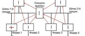
Figure 1 shows the simplest diagram of logical protection of busbars in combination with overcurrent protection at the 10 kV input.
In the event of a short circuit on the busbars or on the outgoing line, protection is activated at the input from the supply transformer (relay KA is activated).
The overcurrent protection at the input is adjusted in time from the protection of outgoing lines and acts to open the circuit breaker in two cases:
– failure of protection or outgoing line switch;
– short circuit on busbars.
Figure 1. Bus logic protection circuit
In the event of a short circuit on any outgoing line (CL1 - CLn), current relay KA1 is activated in its circuit and current relay KA in the input circuit. The KA1 contacts block the protection action on the KL relay.
When there is a short circuit on the buses, the KA relay in the input circuit is triggered and none of the KA1 relays in the outgoing line circuits are triggered. Relay KL is activated and acts to open the input switch with automatic reclosure prohibited.
The scheme is quite simple, but has a number of disadvantages:
1. When testing the protection of any connection, the entire circuit is broken and the protection is disabled.
2. A large number of series-connected elements reduces the reliability of the circuit as a whole. Contact failure in any current relay or connecting wires leads to protection failure.
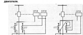
The diagram shown in the following figure is more convenient and reliable. Current relays of all outgoing lines are connected in parallel. To exclude accidental activation of the protection during checks, the relay protection and protection of connections is switched on in series with the contacts of its own switches. In this case, the KL relay acts as a blocking one.
Figure 2. Bus logic protection circuit
The “Arc MT” protection device is a microprocessor-based complex of technical means against arc faults.Purpose:
— Protection of operating personnel from injuries and damage caused by an open electric arc;
— Elimination of destruction in reactor plant cells and sections;
— Reducing the time to detect and eliminate the consequences of an arc fault;
— Reducing costs associated with power supply disruptions.
Application area:
— Switchgear voltage 0.4-35 kV;
— Cells KRU, KRUN, KSO;
— Complete transformer substations (CTS), KTPSN, etc.
Equipment:
The device consists of the following interconnected hardware components:
— Central unit DUGA-BC (with a channel for communication with the automated control system RS-485/FOCL or other, at the choice or suggestion of the Customer);
— Arc fault recording units ( BR ).
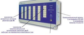
Block "DUGA-BC"
Provides:
— BR serviceability monitoring;
— Performing the functions of Level Level Protection and Level Control Level with programmatic setting of time delays;
— Formation of the ATS prohibition signal;
— Formation of the signal “Reset FTD” (if the photothyristor sensors do not return to their original state);
— Diagnostics and blocking of a faulty sensor;
— Monitoring the serviceability of control circuits of input and sectional switches controlled by the unit;
— Selective shutdown of switches of switchgear inputs, power transformers, sectional, outgoing connections of switchgear.
— Continuous self-diagnosis during the entire operating time
— Recording, viewing, printing, saving and deleting diagrams of emergency processes;
— Event logging with 10ms discreteness;
Possesses:
— Built-in calendar and clock function;
— The ability to quickly connect to a PC;
— Possibility of inclusion in the automated control system as a lower-level subsystem (RS-485 interface; fiber-optic communication line, other, at the Customer’s request) with the ModBus exchange protocol.
In addition, Block Duga-BC:
1. Operable during power interruptions of up to 0.5 s;
2. Ensures readiness for work after applying operational current within 0.25 s;
3. Does not operate falsely and is not damaged:
— during power interruptions of any duration with its subsequent restoration;
— when supplying operational direct current voltage of reverse polarity;
- in case of ground faults in operational current circuits.
4. Has an operating temperature range from - 40 to + 55 ° C;
5. Has a service life of 15 years;
6. Warranty period – 10 years.
Main technical characteristics of the DUGA-BC Block
1. Supply voltage:
— 220 V (+20/-60%) direct, rectified or alternating current;
— 110 V (± 20%) DC.
2. Supply voltage for discrete inputs: - 220 V DC; - 110 VDC.
H. Overall dimensions (WxHxD) - 130x300x298 mm;
4. Weight - no more than 6 kg.
Main characteristics of arc fault recording units (AR)
The device can use the following types of sensors:
— fiber-optic sensors;
— photothyristor sensors;
— valve pressure sensors.
Characteristic
| "ARC-O" | "DUGA-F" | |
| Number of inputs | 4 | 4 |
| Sensor type | Fiber Optic | Valve or photothyristor |
| Number of outputs | 5 | 5 |
| Output type | Contactless | Contactless |
| Response time | 15 ± 0.5 ms | No delay |
The “DUGA-O” and “DUGA-F” arc fault recording units provide:
— Four LED indicators with acknowledgment from a local button; — Alarm about lack of operational power or unit malfunction.
1. Overall dimensions of the blocks (WxHxD) 115x110x53 mm.
2. Block weight - no more than 0.2 kg.
— General operating instructions —
DUGA-BC – Central sectional arc protection unit.
DUGA-F – Arc fault registration unit with connection of photothyristor or valve sensors.
ARC-0 – Arc fault registration unit with connection of fiber-optic sensors.
SEND A REQUEST