Location on the equipment
Depending on the type of electrical equipment, GOST standardizes the marking option and the place on the housing where the connection to ground should be indicated:
- Grounding symbol near the clamp/clip on the shield. According to paragraph 6.4.6 of GOST R 51778 of 2001, the designation must be located at the clamp. Additionally, a sign marks the place where the neutral protective conductor PE is connected.
- “Grounded” sign next to the connection between the metal parts of the housing and the PE conductor. The option is due to the requirements of safety rules 08-624-03. A sticker can be glued to the case or the corresponding symbol can be engraved directly into the metal.
Important! The grounding sign is applied to the surface of the electrical panel in any indelible way. The junction of the grounding cable and the shield itself is cleaned of corrosion, and some of the paint is removed from the connected area.
Deaf neutral immersion
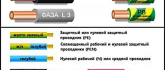
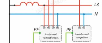
Grounding systems are divided into two large groups: with a solidly grounded neutral and with an isolated one. In the first type of circuit, the neutral conductor (denoted N) is always grounded and can be independent of the protective PE conductor, or can be connected to it to form a PEN conductor.
If the neutral wire is combined with a protective conductor, it forms a TN-C system, if carried out separately - a TN-S system, in the case when it is combined at a substation with a protective conductor, and at the entrance to the building it is divided into two conductors - protective PE and functional N , the TN-CS system is formed. Another type is a system in which the neutral conductor is grounded at the substation and three-phase current is supplied to the consumer through four wires, one of which is zero N. This is a TT system.
Application of the TN-C system
The TN-C system was widely used previously with the so-called two-wire network. In this case, there was no grounded contact in the sockets. In networks designed according to this system, the neutral wire was grounded, but if it broke, all devices remained energized. This forced the housing of each individual electrical appliance to be grounded. This system is not designed in modern buildings under construction. Only used in old buildings.
Application of the TN-S system
The TN-S system is more advanced, has a high degree of electrical safety, since it has a separate grounded conductor, but its cost is unreasonably high. With three-phase power, you have to lay five wires from the source - three phases, a neutral and a protective conductor PE.
To eliminate the shortcoming of the TN-S system, TN-CS was created. It provides one conductor PEN, which is a common wire grounded along the entire length from the power source to the entry into the building, and before entry it is divided into a neutral N and a protective conductor PE. This system also has a significant drawback. If the PEN conductor is damaged along the section from the substation to the building, all devices connected inside the building remain under dangerous voltage. For this system, the PUE (Electrical Installation Rules) require measures to provide additional protection for the PEN conductor from mechanical damage.
CT grounding type
The TT system is used to supply electricity outside the city and in rural areas through power lines installed on poles. Connecting electrical installations via this system is permitted only if it is impossible to ensure all electrical safety conditions in the TN system and avoid unjustified material costs. When contacting electrical appliances, protection against current must be carried out by turning off the power in the circuit. For this purpose, the rules prescribe special products - residual current devices - RCDs.
Options for marking electrical equipment
Most often, a symbol or letter designation is applied to the shields or control panels directly at the manufacturer. The designation location has a convex or depressed relief surface. On new production lines, the “grounded” sign on the shields is cast directly during the manufacture of the metal or plastic housing.
Regardless of whether there is an embossed marking or not, the ground symbol is additionally colored for visual highlighting on the surface of the housing.
For old electrical appliances, production usually simply uses a grounding sign sticker, which is glued to a special adhesive compound or using adhesive tape. As a result, it is possible to quickly mark all the panels and significantly save money. It is worth noting that the use of a grounding symbol in the form of a sticker does not contradict the current GOST.
The essence of grounding
Why do you need grounding if everything works fine without it? Moreover, in normal operation no current flows through the protective ground wire at all.
The key word here is “protective”. Who does grounding protect and from what? It protects human bodies from the effects of electric current. And what it protects against is to ensure that dangerous voltage does not appear on the human body under any circumstances, and that current does not flow through the person.
Let's imagine the situation. There is some electrical appliance, for example an iron. The iron is connected through this plug.
Old plug without grounding pin
Older readers remember these very well; they were constantly unwinding, and attaching a flexible wire to them was a pain.
The body of the iron is partially metal. What happens if a phase suddenly gets on the body? In principle, nothing, the iron can even continue to work. But its body will be at a potential of 220V relative to ground. And since we all walk on the earth, if we touch the metal body of such an iron, current will flow through us.
And then - depending on your luck. If the skin and floor are dry, it will just tug a little...
But if the body of the iron is grounded, then when the phase wire hits the body, it will connect to the ground and go into the ground. In this case, an actual short circuit will occur and the circuit breaker of this line will be knocked out. And the body will remain as it was at zero potential.
In other words, if a phase suddenly gets onto the body of the device, this is no longer a human problem. This is a problem with the device itself and the circuit breaker, which must disconnect this device from the phase wire.
Why does the circuit breaker turn off? If the phase wire touches the protective (grounding) conductor, this is equivalent to a short circuit, that is, the maximum possible current in the circuit. And the machine will work due to electromagnetic protection.
Let me remind you that there is a time-current characteristic of the circuit breaker, and during a short circuit the circuit breaker will operate in the right zone of the characteristic, where the shutdown time tends to zero. Read more in my article about choosing a circuit breaker.
That is, the current in the protective grounding wire flows only at the moment of an accident, the rest of the time it is useless. Therefore, they used to save on it and use a two-wire power system, in which there is only zero and phase.
How is grounding indicated in diagrams and drawings?
When designing electrical circuits on a production line, not only structural elements, switching devices and control equipment are marked, but also the location of the ground loop.
The regulatory document, which specifies all the features of the sign designation on the diagrams, is GOST 2.721 of 1974. Designation of a silent and protective version of grounding signs in the drawings
Important! To select the correct symbol, special attention must be paid to the characteristics of the equipment to be grounded. Depending on the type of grounding, alphabetic symbols (N, PE, PEN) are added to the icon.
Designation of electrical elements on diagrams
To understand what exactly is shown on a diagram or drawing, you need to know the decoding of the icons that are on it. This recognition is also called blueprint reading. And to make this task easier, almost all elements have their own symbols. Almost, because the standards have not been updated for a long time and some elements are drawn by everyone as best they can. But, for the most part, symbols in electrical diagrams are in regulatory documents.
Symbols in electrical circuits: lamps, transformers, measuring instruments, basic components
Dimensions of the grounding sign according to GOST 21130-75
The specified GOST specifies not only the dimensions, but also the methods of applying the sign on the equipment of the manufacturer of panels and other electrical equipment. 4 types of designation are regulated:
- Stamping method.
- Casting in steel case.
- Impact method.
- Pressing method in plastic cases.
Clause 3.1 of the above GOST specifies the possibility of making signs using appliqué, paint, or photochemical methods. The only strict requirement is their size:
- When casting or pressing on the body
| H | H1 | D* | b | h | r |
| 5 | 3,6 | 10 | 0,7 | 2,5 | 0,35 |
| 8 | 6,0 | 16 | 1,2 | 4,0 | 0,6 |
| 10 | 7,0 | 20 | 1,4 | 5,0 | 0,7 |
| 14 | 9,0 | 25 | 1,8 | 5,5 | 0,9 |
| 22 | 15,0 | 40 | 3,0 | 9,0 | 1,5 |
| 28 | 17,5 | 45 | 3,5 | 8,5 | 1,75 |
| 30 | 20,0 | 50 | 4,0 | 10,0 | 2,0 |
| 50 | 35,0 | 90 | 7,0 | 20,0 | 3,5 |
- When manufactured using the impact method
Selecting the cable cross-section
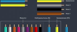
The cable usually consists of 2-4 cores. The cross-section (more precisely, the cross-sectional area) of the core is determined by its diameter.
Based on practical considerations, at low current values, the cross-section of the copper conductor is taken to be at least 1 mm2, and for the aluminum conductor - 2 mm2. At sufficiently high currents, the wire cross-section is selected according to the connected power. It is usually assumed that a load of 1 kW requires a core cross-section of 1.57 mm2. From this follow the approximate values of the wire cross-sections, which should be followed when choosing its diameter. For aluminum - this is 5A per 1 mm2, for copper - 8A per 1 mm2. Simply put, if you have a 5 kW instantaneous water heater, then you need to connect it with a wire rated at least 25A, and for copper the cross-section should be at least 3.2 mm2.
Pixabay
Power cable AVVG: aluminum cores (1-4), cross-section from 2.5 to 50 mm2, polyvinyl chloride insulation, polyvinyl chloride sheath. Designed for installation in both dry and wet areas.
VVG power cable: copper cores (1-4), cross-section from 1 to 50 mm2, polyvinyl chloride insulation, polyvinyl chloride sheath. Used for laying in dry and damp areas.
Please note that from a number of preferred cross-sectional values (0.75; 1; 1.5; 2.5; 4; 6 mm2, etc.) for aluminum wires, the cross-section is chosen one step higher than for copper, since their conductivity is approximately 62% of the conductivity of copper. For example, if, according to calculations, a cross-sectional value of 2.5 mm2 is needed for copper, then for aluminum you should take 4 mm2, if for copper you need 4 mm2, then for aluminum - 6 mm2, etc.
Pixabay
Wires for internal power and lighting networks are often placed in protective corrugated plastic hoses.
VBBShv cable: copper polyvinyl chloride along the core, polyvinyl chloride sheath, armor made of galvanized steel strips, sealed outer hose. Can be used wherever there is a danger of mechanical damage to the wiring during operation.
In general, it is better to choose a cable for your home with a larger cross-section than required, in case you want to connect something else? In addition, it is necessary to check whether the cross-section of the wires is consistent with the maximum actual load, as well as with the current of the protective fuses or circuit breaker, which are usually located next to the meter.
So, you have finally decided on the material and cross-section. The next step is to select the brand of cable or wire.
Image Features
The main document regulating the designation of grounding is GOST 21130-75. It specifies the location of application and features of the image depending on the type of equipment, as well as its dimensions.
According to GOST requirements, this image is applied to the body of electrical equipment near the point where the grounding cable is connected to the device. Additionally, the image must be applied next to the terminal for connecting the neutral protective conductor (PE). Also, the grounding symbol must be depicted inside the electrical panel to which electrical installations or wiring are connected.
The grounding symbol on the equipment can be applied with paint, in the form of a sticker, engraved on the case, or made in any other way to ensure its preservation during the operation of the product. That is, the image must be indelible and positioned in such a way as to avoid damage or blurring.
In addition to marking contacts on electrical installations, it is recommended to mark the locations of grounding loops.
Additionally, letters indicating the type of grounding may be shown next to it.
Graphic options
The grounding icon on drawings and electrical circuit diagrams is regulated by GOST 2.721-74 and the unified system of design documentation (ESKD). These regulatory documents describe how grounding is designated in electrical engineering, as well as the location where equipment is connected to the ground loop. Its dimensions, proportions and methods of depiction are also specified.
Depending on the type and features of connecting the electrical installation to the circuit, there are 4 main ways to indicate grounding in the diagram:
Grounding sign on diagrams
- One vertical line and 3 horizontal lines, located one below the other, each subsequent horizontal line is smaller than the previous one, this option is a standard image of grounding;
- The second option differs from the first in the incomplete circle in which the sign is enclosed; it is used to indicate the connection to the “ground” of separate electrical installations that are not included in the common ground loop;
- In the third case, the circle described around the sign is complete; this option denotes a connection to a common grounding bus of live parts that are not energized under normal conditions;
- The last version of the grounding symbol resembles a rake and indicates the connection of the device to the ground loop through its body.
Designation methods
There are several options for how grounding is designated. In the case of the manufacture of cast parts for electrical equipment, it is cast together with metal or plastic parts. Previously, the option of manufacturing by stamping or by embossing was often used. Thus, the grounding sign on the equipment was either convex or concave, depending on the side from which it was applied.
Note! Regardless of the manufacturing method, it should be painted in bright colors to provide visual highlighting of the connection point to the circuit.
The use of stickers with the image of the grounding sign does not contradict the requirements of GOST(r) 51778-200. The main requirement for stickers with the image of a grounding sign is to ensure their visibility and maintain the quality of the design for a long time. To prevent the sticker from coming off over time, it is recommended to stick it on a clean, flat surface. During the gluing process, it is necessary to carefully level the sticker, removing all the air from under it. If the sticker does not have an adhesive layer on the back of the image, it is fixed with transparent adhesive tape.
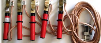
Grounding sign stickers
4.2.134
Open switchgear and substations of 20-750 kV must be protected from direct lightning strikes. Protection against direct lightning strikes is not required for 20 and 35 kV substations with transformers with a unit capacity of 1.6 MVA or less, regardless of the number of such transformers and the number of thunderstorm hours per year, for all outdoor switchgear of 20 and 35 kV substation in areas with thunderstorm hours per year are no more than 20, as well as for outdoor switchgear and substation 220 kV and below at sites with an equivalent earth resistivity during the thunderstorm season of more than 2000 Ohm m with the number of thunderstorm hours per year not more than 20.
Buildings of closed switchgear and substations should be protected from direct lightning strikes in areas with more than 20 thunderstorm hours per year.
The protection of closed switchgear and substation buildings with metal roof coverings should be carried out by grounding these coverings. If there is a reinforced concrete roof and continuous electrical connection of its individual elements, protection is carried out by grounding its reinforcement.
The protection of closed switchgear and substation buildings, the roof of which does not have metal or reinforced concrete coverings with continuous electrical connection of its individual elements, should be carried out with rod lightning rods, or by laying a lightning protection mesh directly on the roof of the buildings.
When installing rod lightning rods on a protected building, at least two down conductors must be laid from each lightning rod on opposite sides of the building.
The lightning protection mesh must be made of steel wire with a diameter of 6-8 mm and laid on the roof directly or under a layer of non-combustible insulation or waterproofing. The grid should have cells with an area of no more than 150 m (for example, a cell 12x12 m). The mesh nodes must be connected by welding. Down conductors connecting the lightning protection grid to the grounding device must be laid at least every 25 m around the perimeter of the building.
Metal and reinforced concrete (if there is at least part of the unstressed reinforcement) building structures should be used as down conductors. In this case, a continuous electrical connection from the lightning rod to the ground electrode must be ensured. Metal elements of the building (pipes, ventilation devices, etc.) should be connected to a metal roof or lightning protection mesh.
When calculating the number of reverse overlaps on a support, one should take into account the increase in the inductance of the support in proportion to the ratio of the distance along the down conductor from the support to the grounding to the distance from the grounding to the top of the support.
When entering into closed switchgears and substations of overhead lines through bushings located at a distance of less than 10 m from current conductors and other associated live parts, these inputs must be protected by RF or appropriate surge arresters. When connecting to the substation grounding mains at a distance of less than 15 m from power transformers, the conditions of 4.2.136 must be met.
For electrolysis buildings located on the territory of the substation, premises for storing hydrogen cylinders and installations with hydrogen receivers, the lightning protection mesh must have cells with an area of no more than 36 m (for example, 6x6 m).
Protection of buildings and structures, including explosive and fire hazardous ones, as well as pipes located on the territory of power plants, is carried out in accordance with technical documentation approved in the prescribed manner.
Dimensions
According to the requirements of GOST 21130-75, the parameters of the symbol image differ depending on the method of its application to the body of the electrical installation. For example, the minimum diameter of a sign made by casting or stamping is 10 mm, and for one made by impact, this parameter will be 14 mm. One of the most commonly used dimensions of the ground safety sign is 30 x 30 mm. More details on the dimensions of the grounding symbol can be found in clause 3.1 of the above GOST.
Design and dimensions of grounding signs made by casting in metal (including non-ferrous) and pressing into plastic class=”aligncenter” width=”768″ height=”370″[/img] Dimensions of grounding signs made by casting methods
Design and dimensions of grounding signs made by impact
Dimensions of grounding signs made by impact
Another important requirement for the picture of the grounding sign is its color scheme. According to GOST, the main background must differ from the color of the equipment on which it is applied. Most often, yellow is used as the main background, and the icon itself and the outlines of the circle are made black.
The best way to update your business signs is to purchase stickers. The grounding sign on stickers can be in vector format or in the form of a picture. The stickers have a service life of up to 2 years, and replacing them is easy. You can also download a grounding sign stencil and apply the symbols with paint. When designing a grounding loop and installing new equipment, it is better to check in advance for the presence of “Grounded” icons on their housings.
Marking methods
There are several ways to apply such symbolism:
- stamping,
- metal casting,
- impact method,
- pressing in plastic.
In this case, the marking will be convex or depressed.
But not all elements and devices can be marked in this way. However, regulatory documents do not prohibit applying special symbols in other ways, for example, appliqué, paint, etc. Therefore, applying a designation using a sticker with the desired symbol has become quite common. In this case, the main attention should be paid to the size of the sign - it must strictly comply with the standards specified in the PUE and GOST 21130-75.
It should be noted that a symbol made by casting or pressing must differ in size from symbols produced by impact. Regardless of the diameter of the sign's circle, the line around it is painted in a color that contrasts with the color of the device - usually black or yellow.
What does a grounding sign look like?
Grounding circuit: PUE standards
The grounding sign (ЗЗ) appears as a black symbol on a bright yellow background. The logo icons must be located next to the grounding bus mount. According to GOST ZZ, they must have a certain type of execution. Methods for applying and installing glazing can be completely different.
Metal plate
The manufacturer itself installs a logo on its products in the form of a convex or depressed image on a metal plate. The plaque is either screwed on or welded using spot welding.
Sticky symbols
GOST does not prohibit the use of stickers. Typically, these emblems have an adhesive backing. Remove the protective film from the back of the sign and press it to the clean surface of the body in the right place. The sticker must be ironed with a rag or a clean cloth so that no air bubbles remain under the sign. If this is not done, the sticker may come off over time.
Adhesive signs are made using high quality materials. This allows them to be used in conditions of significant vibration and high humidity levels.
Cast images
When manufacturing a flask for casting housings of electrical devices, the manufacturer inserts a template with a grounding logo into the casting mold. ZZ is obtained in the form of a relief imprint on the body of the equipment casing.
In this case, the sign is painted by hand with black and yellow enamel. The painted surface is periodically updated. GOST 21130-75 prescribes a clear execution of the design, indicating the detailed dimensions of the design elements. This applies not only to metal, but also to plastic cases made by injection molding.
Stamp
Drawing images using the stamping method has been used for quite some time. Most often, the method is used in the manufacture of non-ferrous metal cases. The dimensions of the stamped ground symbol detail are slightly different from the cast ones. They are indicated in the table of the same GOST 21130-75: this is the diameter of the circle, the length and thickness of the lines, the angles of the figure, etc.
Important! In both cases, the edging of the circle and the logo itself are most often painted with radical black paint, while the field of the sign itself is bright yellow or orange.
V(V)
| Damn 2 | ||||||||||||||||||||||||||||
| An example of a symbol for a contact washer for a stud with a diameter of 5 mm: Contact washer 5 GOST 21130-75 (Changed edition, Amendment No. 2, 4, 5). We advise you to study What voltage should be on the battery1.2.2. The material of the contact washer is brass grade L63 according to GOST 15527-70. 1.2.3. The contact washer coating is 09 or M9 according to GOST 9.306-85. (Changed edition, Amendment No. 4). 1.3. The design and dimensions of type ZB clamps must correspond to those indicated in Fig. 3 and in table. 3. Version 2
|
What does a grounding sign look like?
The grounding sign (ЗЗ) appears as a black symbol on a bright yellow background. The logo icons must be located next to the grounding bus mount. According to GOST ZZ, they must have a certain type of execution. Methods for applying and installing glazing can be completely different.
Metal plate
The manufacturer itself installs a logo on its products in the form of a convex or depressed image on a metal plate. The plaque is either screwed on or welded using spot welding.
Sticky symbols
GOST does not prohibit the use of stickers. Typically, these emblems have an adhesive backing. Remove the protective film from the back of the sign and press it to the clean surface of the body in the right place. The sticker must be ironed with a rag or a clean cloth so that no air bubbles remain under the sign. If this is not done, the sticker may come off over time.
Sticker near the bus terminals
Adhesive signs are made using high quality materials. This allows them to be used in conditions of significant vibration and high humidity levels.
Cast images
When manufacturing a flask for casting housings of electrical devices, the manufacturer inserts a template with a grounding logo into the casting mold. ZZ is obtained in the form of a relief imprint on the body of the equipment casing.
In this case, the sign is painted by hand with black and yellow enamel. The painted surface is periodically updated. GOST 21130-75 prescribes a clear execution of the design, indicating the detailed dimensions of the design elements. This applies not only to metal, but also to plastic cases made by injection molding.
Dimensions ZZ
Stamp
Drawing images using the stamping method has been used for quite some time. Most often, the method is used in the manufacture of non-ferrous metal cases. The dimensions of the stamped ground symbol detail are slightly different from the cast ones. They are indicated in the table of the same GOST 21130-75: this is the diameter of the circle, the length and thickness of the lines, the angles of the figure, etc.
Important! In both cases, the edging of the circle and the logo itself are most often painted with radical black paint, while the field of the sign itself is bright yellow or orange.
Which places are indicated by a grounding sign?
As you know, the main purpose of grounding is to ensure electrical safety. And the main purpose of the grounding sign is to indicate the specific place where the equipment is connected to the grounding loop.
Where is it customary to put symbols indicating the connection of the equipment with the “ground”? First of all, these are the places where the protective conductors are connected to the main grounding buses, near the terminals or studs for connecting the protective conductor.
Friends, let's figure out where grounding signs are installed in electrical installations, according to the rules and GOST.
The first regulatory document that says about applying the grounding sign GOST R 51778-2001 “Distribution panels for industrial and public buildings” Clause 6.4.6 of this document says that the grounding sign should be applied near the grounding terminal, as well as near the terminal where the neutral protective one is connected conductor - PE.
The next regulatory document is GOST 12.2.007.0-75 ELECTRICAL PRODUCTS. General safety requirements. Paragraph 3.3.5 states that an indelible (implied during operation) grounding sign must be applied in any way near the connection point of the grounding conductor. By the way, the same paragraph says that the place for connecting the grounding conductor must be cleaned of corrosion, and the connected area (sleeve) must not have surface paint.
Regarding cleaning from corrosion, I think this is a very important note. I personally spent a long time looking for where this action is written.
We advise you to study the DIY car battery charger
Let's go further - PB 08-624-03 “Safety Rules in the Oil and Gas Industry.” Clause 1.5.14 states that the “grounding” symbol must be depicted in the place where the metal parts of the equipment are connected to the PE protective conductor.
And of course, let’s not forget about our native PUE. Paragraphs 1.7.118 and 1.7.119 of which also stipulate the application of grounding identification marks.