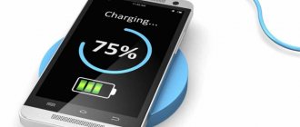
How to properly charge a lithium-ion battery and significantly extend the life of 18650 batteries. What current should I use to charge a Li-Ion 18650 battery?
Batteries of this size have several important indicators:
- capacity (mAh – mAh)
- discharge current (A)
- charge current (A)
- maximum number of discharge cycles
In this article, I'll tell you about the last option and how this information can help you extend the life of your batteries.
Types of chargers
The screwdriver is supplied with one or two batteries with a charger. Now there is a trend among power tool manufacturers to sell products without batteries. This marketing technique forces buyers to purchase models from manufacturers that are already in their arsenal. In any case, if the battery is purchased, even separately, you can also take a charger for it. It's also a matter of mechanical design - a charger from one manufacturer will most likely not be suitable for charging another.
Almost always, a device for replenishing energy is optimized for a specific type of battery, charges it in the most favorable current mode, and stops charging automatically at the end of the process. Therefore, when purchasing a charger and batteries from the same manufacturer, you don’t have to think about compatibility if the charger is intended for batteries of the same manufacturer and type.
Charger.
In most cases, chargers are sold in a pulse version. But for nickel-cadmium batteries there are chargers that are considered professional (the price is appropriate). They are called pulse-reverse. For every positive pulse, they produce a surge of negative polarity of small amplitude. This eliminates the memory effect inherent in Ni Cd batteries and preserves their capacity.
Converting a screwdriver to lithium, part two, charging correctly
Last time I told you how to properly remake a battery for a cordless tool. I also wrote that I would talk about the features of the charge, and the subject of the review this time will be the DC-DC converter board. If anyone is interested, please come visit. Initially, I planned to limit myself to two parts, reworking the battery and charger. But while I was preparing the review, an idea matured in my head for the third part of the review, a more complex one. And in this part I will tell you how you can remake your original transformer charger if it is still working, or if the power transformer is still alive.
The converter board was ordered quite a long time ago in the amount of several pieces (in reserve), it was ordered specifically for this alteration, because it has some features, however, I won’t go too far, let’s be consistent.
To begin with, I will divide chargers into three main types: 1. The simplest ones are a transformer, a diode bridge and several parts. Ultra-budget tools are equipped with such chargers. 2. Branded. Essentially the same thing, but it already includes simple “brains” that automatically turn off the charge at the end. 3. “Advanced” - switching power supply, charge controller, sometimes charging several batteries at the same time.
A tool from the first category rarely gets remade, since it is often easier (and cheaper) to buy a new one, while the third category usually has its own difficulties in remaking. In principle, it is possible to remake devices of the third group, but not within the scope of this article, since there are a lot of types of such chargers and each requires an individual approach.
This time I will remake the charger from the second group, a proprietary one, although simple. But this rework has much in common with the first group, and therefore will be useful to a larger number of readers.
In order to charge the battery, you need to not just connect it to the power supply; such an experiment usually does not end very well. You need to connect it to the charger. And here comes a slight misunderstanding, since quite a lot of people are accustomed to calling small power supplies from which they charge their smartphones, tablets and laptops chargers. These are not chargers, but power supplies.
What is the difference between a charger and a power supply? The power supply is designed to provide a stabilized voltage within the range of declared load currents. The charger is usually more complex, since its output voltage depends on the load current, which in turn is limited. In this case, the charger contains a unit that stops charging at the end, and sometimes also protection against connecting the battery in the wrong polarity.
The simplest charger is simply a power supply and a resistor (sometimes an incandescent lamp, which is even better) in series with the battery. This circuit limits the charging current, but as you understand, it cannot do anything else.
It’s a little more complicated when they also install a timer that turns off the charge after a certain time, but this principle quickly “kills” the batteries. For example, this is done in one of the inexpensive chargers for screwdrivers (photo not mine).
The next class comes from more “smart” chargers, although in essence they are not much better than the previous one. For example, here is a photo of a branded Bosch charger designed to charge NiCd batteries.
But all these chargers seem very simple after looking at the modern options for charging lithium batteries.
Of course, the last option does not quite fit into our concept of redesign, since it is desirable that our charger not only charges correctly, but also costs minimal money.
The chargers of Chinese screwdrivers look, of course, much simpler, but again, hardly anyone would want to make such a device from scratch, although this is exactly what I plan to do in the third part, albeit more correctly.
And so, to begin with, let’s assume that we have a charger on our hands that simply does not fit the new type of battery, but is serviceable. Well, or at least his transformer is working. As I wrote above, you can even use just a resistor or a light bulb, but this is “not our method.”
The schematic diagram of a typical inexpensive charger looks something like this: Transformer, diode bridge, thyristor and control circuit. True, sometimes instead of a thyristor there is a relay, the current is not limited in any way and there may be a thermal control circuit against overheating (although this does not always save.
But from this circuit we only need a transformer and a diode bridge, although we will have to add another capacitor, so we will get some initial unchanged part, it is marked in red and will not change further.
The diode bridge is usually located on the board and can be used if necessary (if it is working properly). Those. By and large, you can remove all radio elements from the board, leaving only four diodes and terminals for connecting the battery, and use the board itself as a base. The cathode of the diodes is marked with a stripe, the point where two terminals marked with a stripe are connected is a plus, respectively, the point of connection of the “unlabeled” terminals is a minus. A transformer is connected to the other two connection points.
True, when you open the charger, you can see the following picture (ignore the absence of a transformer): In this case, you will have to unsolder everything.
It is convenient to replace the diodes on the board with a ready-made diode bridge; a transformer is connected to the speaker terminals, + and -, respectively, go further into the circuit. Of course, you can tell how to choose a capacitor, but I advise you not to bother and put one like in the photo, capacity 1000 μF, voltage 35 Volts. The capacity can be larger, for example 2200, and the voltage is 50 or 63 Volts, a large capacity and voltage do not make sense, but will only increase the size of the capacitor. Any capacitor can be used, even a “noname” will do. Yes, it must be installed in any case, regardless of the serviceability of the diode bridge.
Now let’s move on to the charger itself, or rather to its variants; this node is marked with a rectangle in the last diagram. The simplest and at the same time relatively correct way is to install an LM317 voltage stabilizer chip.
But as I wrote above, the charge current must be limited. Yes, many circuits can not only limit, but also stabilize it, but by and large it does not matter to batteries whether the charge current is 1, 2 or 3 Amperes, it does not matter whether it is stable during the charging process or “floating”, it is important that the charge current does not exceed installed for batteries. Although for batteries that are used in screwdrivers it is difficult to exceed it, since they can operate not only at high discharge currents, but also at high charging currents. The simplest solution is to transfer the LM317 microcircuit from voltage stabilization mode to current stabilization mode, or more precisely, add a current stabilization mode. This is achieved by adding one resistor, as shown in the diagram. The resistor value is very easy to calculate: 1.25/I (current in Amperes) = R (resistor value in Ohms). For example, you need a current of 1.5 Amperes, then it will be 1.25/1.5= 0.83 Ohms.
The values of the voltage divider resistors are also quite easy to calculate, but I would advise placing a trimmer in series with the upper resistor in order to accurately set the voltage, since, unlike current, accuracy is important here. You can use a special calculator, but it is not very convenient, so I will offer values without it, for a voltage of 12.6 Volts (3 series batteries of 3.7 Volts) the upper resistor needs 1.5 kOhm, the trimmer in series with it is 200 Ohm, and the lower resistor is 13 kOhm.
I specifically indicated that the tuning resistor is placed in series with the upper resistor. In the event of a break, the output will have a minimum voltage. If you cut off the lower resistor, the output voltage will be maximum. By the way, in common DC-DC converter boards, the opposite is done; in the event of a break in the trimming resistor, they will output the maximum voltage.
Everything is good in the above scheme, simplicity, price, but the high power output negates all the advantages, since you will need a very impressive radiator, so it is not very suitable for high charging currents.
A more correct option would be to use a step-down DC-DC converter. For example this:
Of course, in its original form it will not limit the current, but if desired, it can be modified (in case it already exists). The modification is simple and I already described it in one of my reviews, although at the end I used it as an LED driver, but essentially it doesn’t matter. You need: 1 transistor type BC557 or any analogue (or even the well-known KT361 or KT3107) 2 resistors with a nominal value of 33-200 Ohms of any power. 1 resistor as a current shunt 1 ceramic capacitor 0.1 µF.
The current measuring resistor is calculated very simply, as in the case of LM317, only the values are slightly different. 0.6/I (current in Amps) = R (resistor value in Ohms). For example, you need a current of 1.5 Amperes, then it will be 0.6 / 1.5 = 0.4 Ohms.
The output of the additional circuit is connected to pin 4 of the LM2596 microcircuit; if another microcircuit is used, then we look for the pin marked as FB in the description and connect it to it.
In this embodiment, using a trimming resistor, we set the output voltage (at idle). True, such a scheme may slightly undercharge the batteries, although not much, but this is the price to pay for simplicity. To charge fully, you need to switch the voltage measurement input (one of the voltage divider resistors) to the output of the entire circuit.
All of the above charging methods are workable, but not very convenient. It would be more correct to use a board that “can” not only stabilize the output voltage, but also the current. For example, this scarf. It is very easy to distinguish suitable boards from others; the description should say “DC-DC StepDown”, and the board should have at least two interlinear resistors.
But in addition to adjusting the output current, this board has an additional bonus in the form of an indication: 1. An LED at the top shows the current limiting mode 2. A pair of LEDs at the bottom shows the end of the charge.
The battery charge indication is implemented very simply; the LEDs switch when the current drops below 1/10 of the initially set one. This mode of operation is very common and is used in many simple chargers. Those. for example, we set the charge current to 1.5 Amperes, connected the battery, when the charge current drops below 150 mA, one of the LEDs will go out and the second will light up, thereby indicating that the charging process is complete. Reviews of this board were done by a colleague of ksiman, so it’s easier to provide a link for a more detailed description.
The diagram of this board, also from the above review, may be useful.
It turns out that this board is quite well suited for charging batteries; first we set the end of charge voltage at the rate of 4.2 Volts per element, and then the charge current. For gourmets, you can offer the same board, but with an indication of the charge current and voltage on the battery, but in my opinion, in this case this is unnecessary. I reviewed this board, in fact this is a photo from that review, where I also showed how to make a switching power supply yourself.
This is what this option will look like on a block diagram.
So we slowly got to the subject of the review, which was primarily of interest due to its low price. I have very strong suspicions about the “proprietary” nature of the installed microcircuit, but if you do not use it for the entire declared 3 Amperes, then it is quite viable.
It so happened that initially I did not think of doing a review of this board, and although I bought 4 of them, I only had one left at home, and that one already had traces of my intervention. I desoldered the original LEDs and soldered others.
In its original form, there are three LEDs on the board: 1. Charged. 2. Charge 3. Current limit indication.
How does the indication work? The Charge and Charged LEDs are turned on so that only one of them lights up, so they can be considered as one. In boards without current regulation at which the indication will be triggered, switching occurs when the charging current drops below 1/10 of that set by the resistor - Current limitation. In the board under review, you can set an arbitrary operating current; I would recommend setting it to 1/5.
The current limit indication LED works slightly differently; it lights up when current limitation occurs, i.e. when the current at the set voltage tends to increase more than that set by the regulator. For example, we set the current to 1 Ampere and 10 Volts (conditionally), connected a load that at 10 Volts consumes 0.5 Amperes. The output will be 10 Volts 0.5 Amperes. Then we connected a load, which at 10 Volts will consume 1.5 Amperes, the output will be 1 Ampere and 8 Volts (conventionally), i.e. the board will reduce the voltage to a value at which the output current will not exceed the set one and at the same time the LED will light up.
There are also three trimming resistors on the board: 1. Adjustment of the output voltage. 2. Adjustment of the threshold for indicating the end of charge. 3. Adjustment of the output current limit threshold.
The board is very simple; it contains the LM2596 chip itself, a 78L05 stabilizer and an LM358 comparator. LM2596 is actually a PWM controller. 78L05 is used to power the comparator and as a voltage reference. LM358 “monitors” the current and simultaneously controls the display
A track on a printed circuit board acts as a current shunt. This method of measuring current is not very good, since the current will “float” depending on the temperature of the board, but since the stability of the output current does not matter for us, we can ignore this.
Location of contacts, controls and indications from the product page.
Boards with the ability to limit output current are very suitable for charging batteries. And those boards that have an indication of the end of the charge also allow you to get some convenience, allowing you to know that the battery is charged. But all of the above methods have one drawback: all these options cannot turn off the battery after charging is complete, i.e. stop the process completely. Of course they will tell me how the batteries live in uninterruptible power supplies. But here there is a peculiarity: some types of batteries have a concept - cyclic charging and the so-called Standby, i.e. supportive. The same lead battery is charged in cyclic mode to 14.3-15 Volts, and in standby mode only to 13.8-13.9 Volts.
If the battery is not disconnected, then a small charging current will always flow through it, and although lithium batteries are a little “lucky” in this regard, their current drops very significantly, but still, it is not recommended to leave them in this mode. The fact is that cadmium or lead ones simply begin to break down, heat up and that’s it, but with lithium ones a fire is possible. Yes, lithium batteries have a safety valve, but extra protection is never a bad thing.
The question is often asked - what about the protection board, because it can turn off the battery after charging is complete. It can and not only can, but it will turn it off, only it will do this not at 4.2 Volts per element, but at 4.25-4.35 Volts, since the shutdown function for it is more protective than the main one. Therefore, doing this is highly not recommended.
That’s actually why I came up with a simple circuit that will turn off the battery when the charge is complete. The operating principle is very simple (and therefore has some limitations). We connected the battery, since capacitor C1 is discharged, a current flows through it, which opens the transistor, and it supplies current to the relay. The relay connects to the charging battery, and then the relay is powered through an optocoupler, which is connected to the charge indication output of the converter board.
Accordingly, a small scarf was developed, and in a universal design.
Well, then everything is simple and familiar, we print the board on paper, transfer it to the PCB, and etch it. For those interested, the process of manufacturing printed circuit boards is shown in detail in this review.
When I came up with the circuit, I tried to simplify it as much as possible, using a minimum of components. 1. Relay - any with a winding voltage of 12 Volts (for options with 3-4 batteries) and contacts designed for a current of at least 2x the charging current. 2. Transistor - BC846, 847, or the well-known KT315, KT3102, as well as analogues. 3. Diode - any low-power diode. 4. Resistors - any in the range of 15 - 33 kOhm 5. Capacitor - 33-47 uF 25-50 Volts. 6. Optocoupler - PC817, found on most power supply boards.
Collected the fee.
I made the board universal; you can use a field-effect transistor instead of a relay; some of the components remain the same as before. In addition, this option is more universal, as it is suitable for screwdrivers with 3-4-5 batteries. But this board has a drawback. There is a “parasitic” diode inside the transistor, and if you leave the battery connected to the charger but unplug it, the battery will discharge through the charger circuit. In the version that I showed above, there will be a similar problem, but there the current is very small, about 0.5 mA, and it will take about 4000 hours for the battery to completely discharge.
Slightly different values are used here, although essentially only the value of resistors R4 and R5 is important. The value of R5 must be at least 2 times less than that of R4.
We select components for the future board. Unfortunately, you will most likely have to buy a transistor, since such devices are rarely used in finished devices; they can be found on motherboards, but extremely rarely.
The board is universal, you can use a relay and make it according to the previous circuit, or you can use a field-effect transistor.
Now the block diagram of the charger will look like this: Transformer, then diode bridge and filter capacitor, then the DC-DC converter board, and finally the shutdown board. I did not sign the polarity of the charge indication pins, since it can be different on different boards; if something doesn’t work, then you just need to swap them, thereby changing the polarity to the opposite.
Let's move on to the actual alteration. First of all, I cut the tracks from the output of the diode bridge, the battery connection terminals and the charge indication LED. The goal is to disconnect them from the rest of the circuit so it doesn't interfere with the "process". You can, of course, simply unsolder all the parts except the bridge diodes, it will be the same, but it was easier for me to cut the tracks.
Then we solder the filter capacitor. I soldered it directly to the diode terminals, but you can install a separate diode bridge, as I showed above. Remember that a terminal with a stripe is a plus, without a stripe a minus. The capacitor has a long lead - a plus.
The printed circuit boards on top did not fit at all, constantly resting against the top cover, so we had to place them from below. Here, of course, everything was not so smooth, they had to bite out one stand and saw down the plastic a little, but in any case, they were much better here. They even increased in height with a margin.
Let's move on to the electrical connections. To begin with, we solder the wires, at first I wanted to use thicker ones, but then I realized that I simply couldn’t turn around with them in a cramped case and took ordinary multi-core wires with a cross-section of 0.22mm.sq. I soldered the wires to the top board: 1. On the left is the power input of the converter board, connected to the diode bridge. 2. On the right - white and blue - the output of the converter board. If a disconnect board is used, then to it, if not, then to the battery contacts. 3. Red with blue - output indicating the charging process, if with a shutdown board, then to it, if not, then to the indication LED. 4. Black with green - Indication of the end of the charge, if with a disconnect board, then to the LED, if not, then we do not connect it anywhere.
So far only the wires to the battery are soldered to the bottom board.
Yes, I completely forgot, you can see the LED on the left board. The fact is that I completely forgot and unsoldered all the LEDs that were on the board, but the problem is that if you unsolder the current limit indication LED, the current will not be limited, so it must be left (marked on the board as CC/CV) , be careful.
In general, we connect everything as shown, the photo is clickable.
Then we glue double-sided tape to the bottom of the case, since the bottom of the boards is not entirely smooth, it is better to use thick tape. In general, everyone does this moment as conveniently as possible, you can glue it with hot glue, screw it with self-tapping screws, nail it 
We glue the boards and hide the wires. As a result, we should have 6 wires left free - 2 to the battery, 2 to the diode bridge and 2 to the LED.
Don’t pay attention to the yellow wire, this is a special case, I only had a 24 Volt relay, so I powered it from the converter input. When preparing wires, always try to follow the color coding, red/white is positive, black/blue is negative.
We connect the wires to the original charger board. Here, of course, everyone will have their own way, but I think the general principle is clear. You need to especially carefully check that the connection to the battery terminals is correct; it is better to first check with a tester where the plus and minus are; however, the same applies to the power input.
After all these manipulations, it is imperative to check and possibly reset the output voltage of the converter board, since during the installation process you can reset the setting and get at the output not 12.6 Volts (the voltage of three lithium batteries), but for example 12.79. You can also adjust the charge current.
Since setting the threshold for indicating the end of charge is not very convenient, I recommend buying a board with two trimming resistors, it’s easier. If you bought a board with three trimming resistors, then to configure it you need to connect to the output a load approximately corresponding to 1/10 - 1/5 of the set charge current. Those. if the charge current is 1.5 Amperes and the voltage is 12 Volts, then it can be a resistor with a nominal value of 51-100 Ohms with a power of about 1-2 Watts.
We've set it up and check it before assembly. If you did everything correctly, then when you connect the battery, the relay should activate and the charge will turn on. In my case, the indication LED goes out and turns on when the charge is complete. If you want to do the opposite, you can turn on this LED in series with the input of the optocoupler, then the LED will light while charging is in progress.
Since the title of the review still mentions the board, and the review is about redesigning the charger, I decided to check the board itself. After half an hour of operation at a charge current of 1 Ampere, the temperature of the microcircuit was about 60 degrees, so I can say that this board can be used up to a current of 1.5 Amperes. However, I suspected this from the very beginning; at a current of 3 Amps, the board will most likely fail due to overheating. The maximum current at which the board can still be used relatively safely is 2 Amperes, but since the board is in a case and the cooling is not very good, I recommend 1.5 Amperes.
That's it, we twist the body and set it to full run. I actually had to drain the battery before this, since I charged it in the process of preparing the last part. If a charged battery is connected to the charger, then the relay is activated for 1.5-2 seconds, then turns off again, since the current is low and blocking does not occur.
So, now about the good and the not so good. The good thing is that the conversion was a success, the charge is on, the board disconnects the battery, in general it’s simple, convenient and practical. The bad - If you turn off the charger's power during charging and then turn it on again, the charge will not automatically turn on. But there is a much bigger problem. During the preparation process, I used the board from the previous review, but I also wrote there that the board does not have a controller, and therefore cannot be completely blocked. But smarter boards completely turn off the output in a critical situation, and since it is also an input, when connected to the charger that I modified above, it will not start. Voltage is needed to start, and the board needs voltage to start 
There are several solutions to this problem. 1. Place a resistor between the input and output of the protection board, through which current will flow to the terminals to start the charger, but I don’t know how the protection board will behave, there is nothing to check. 2. Connect the charger input to a separate battery terminal, this is often done with cordless tools with lithium batteries. Those. We charge through some contacts, discharge through others. 3. Do not install a shutdown board at all. 4. Instead of automation, install a button as in this diagram.
At the top there is an option without a protection board, at the bottom there is just a relay, an optocoupler and a button. The principle is simple, we inserted the battery into the charger, pressed the button, the charge began, and we went to rest. Once the charge is complete, the relay will completely disconnect the battery from the charger.
Conventional chargers constantly try to supply voltage to the output if it is below a certain value, but this modification option is inconvenient, and with a relay it is not very applicable. But for now I think it might be possible to do it beautifully.
What can you advise regarding the choice of battery charging options: 1. Just use a board with two trimming resistors (it is in the review), it’s simple, quite correct, but it’s better not to forget that the charger is on. I don’t think there will be any problems for a day or two, but I wouldn’t recommend going on vacation and forgetting the charger is on. 2. Do as in the review. Difficult, with limitations, but more correct. 3. Use a separate charger, for example the well-known Imax. 4. If your battery has an assembly of two or three batteries, then you can use B3. It is quite simple and convenient, in addition, there is a full description in this review from the author Onegin45.
5. Take the power supply and modify it a little. I did something similar in this review.
6. Make your own charger, with all automatic shutdowns, correct charging and extended display. The most difficult option. But this is the topic of the third part of the review, however, it will most likely also include converting the power supply into a charger.
7. Use a charger like this.
In addition, I often encounter questions about balancing the elements in the battery. Personally, I think that this is unnecessary, since high-quality and selected batteries are not so easy to unbalance. If you want something simple and high quality, then it’s much easier to buy a protection board with a balancing function.
Recently there was a question whether it is possible to make the charger able to charge both lithium and cadmium batteries. Yes, it can be done, but it’s better not to, since in addition to different chemistry, batteries also have different voltages. For example, an assembly of 10 cadmium batteries requires 14.3-15 Volts, and an assembly of three lithium batteries requires 12.6 Volts. In this regard, you need a switch that you can accidentally forget to switch. A universal option is only possible if the number of cadmium batteries is a multiple of three, 9-12-15, then they can be charged as lithium assemblies 3-4-5. But common tool batteries cost assemblies of 10 pieces.
That seems to be all, I tried to answer some questions that people ask me in private. In addition, the review will likely be supplemented with answers to your next questions.
The purchased boards are quite functional, but the chips are most likely fake, so it is better to load no more than 50-60% of the declared value.
In the meantime, I’m thinking that you need to have it in a proper charger, which will be made from scratch. So far the plans are: 1. Automatic start of charging when installing the battery 2. Restart in case of power failure. 3. Several stages of charging process indication 4. Select the number of batteries and their type using jumpers on the board. 5. Microprocessor control
I would also like to know what would be interesting for you to see in the third part of the review (you can PM me).
I wanted to use a specialized microcircuit (it seems that you can even order a free sample), but it only works in linear mode, and this causes heating :((((
It might be useful to have a link to an archive with traces and diagrams, but as I wrote above, the additional board most likely will not work with boards that completely disconnect the batteries.
In addition, such conversion methods are only suitable for batteries up to 14.4 Volts (approximately), since chargers for 18 Volt batteries produce voltages above 35 Volts, and DC-DC boards are designed only up to 35-40.
Charging methods
One of the most convenient ways is if you have a universal (laboratory) power source that can adjust the voltage and measure the current. Even better if there is a current limiting mode. In this case, the desired charging current is set, and the source itself increases the output voltage following an increase in this parameter on the battery. But you will have to monitor the end of the process yourself.
You will also have to independently determine the end of the first stage of charging lithium-ion batteries (to control the balancing of the elements, you need to disassemble the battery case, so you have to hope that the BMS board is working) and reduce the current in time.
At the end of the process, the battery must be disconnected in time (monitored when the highest voltage is reached). The charging end voltage is selected from the table. It is necessary to multiply the maximum voltage of a single can by the number of elements. If it is unknown, you need to divide the voltage indicated on the battery case (it is usually too high) by the voltage of one bank and round down.
| Battery type | Nominal level of one element, V | Maximum level of one element, V |
| Li-Ion | 3,7 | 4,2 |
| NiCd | 1,2 | 1,37 |
| NiMH | 1,2 | 1,25 |
Laboratory power supply with current limiting mode.
If there is no such mode, you will have to monitor the current manually. As energy is replenished and the voltage on the battery increases, you need to adjust the voltage yourself, maintaining the selected level using the control ammeter. If the source does not have a built-in meter, you will need to use an external device (for example, a multimeter in the appropriate mode). As a general approach, you can use any regulated power source, but monitoring the parameters on the battery must be mandatory.
General diagram for charging the battery.
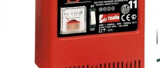
There are tips online to use a car charger. If such a charger allows you to manually regulate the voltage, then it can be used to charge the batteries of screwdrivers. If the device is automatic, then this is not a good idea. Such chargers are designed to work with 12-volt batteries, and household screwdrivers can also be designed for 20-volt power supply (professional ones are even higher). Therefore, it will not be possible to fully replenish energy reserves in these cases. In addition, cars use lead-acid cells, and they require a constant voltage charging mode, which is unacceptable for the cases under consideration.
The video uses inverter charging for a car.
Charging Li-ion batteries - briefly about the operating rules
Your lithium-ion battery should last between 300 and 500 charge and discharge cycles, which is typically 2-3 years. Gradually over this lifespan, lithium-ion batteries will naturally experience capacity degradation due to a number of factors including charging cycling, storage, temperature fluctuations, frequency of use and general aging.
To avoid the risk of damaging the battery, use only the designated smart charger. Our smart chargers have built-in circuitry specifically designed to ensure the correct voltage is applied to our lithium-ion cells, preventing overcharging.
CHARGER FOR Li-Ion BATTERIES
Is it possible to charge the battery without a controller?
The controller when charging the battery is not the main unit. But very important. It supports energy replenishment modes and prevents overcharging (and sometimes overheating), can automatically conduct training cycles, and measure battery parameters. These modes are different for each of the three types of batteries used in screwdrivers:
- lithium-ion;
- nickel-cadmium;
- lithium metal hydride.
Failure to comply with the prescribed modes shortens the service life of the battery and does not allow the capacity to be fully used. In the absence of a controller, you will have to adjust the output parameters of the memory yourself during the entire process.
How to charge a battery, rules
Lithium-ion batteries are similar to people in that they do not behave the same and work best at temperatures that are neither too hot nor too cold.
These batteries perform better at high temperatures than at low temperatures because the heat reduces internal resistance and speeds up the chemical reaction inside the battery. A side effect of this process is that it puts a strain on the battery, which can lead to shortened life in hot conditions for extended periods.
On the other hand, low temperatures increase internal resistance, which increases the load on the battery and reduces its capacity. Batteries that provide 100% capacity at 27°C are typically reduced by 50% at -18°C and so on.
How to charge Li ion batteries correctly?
What you can do: Ambient temperature has a significant impact on battery health. To maximize performance and/or battery life, operate and store in a cool, dry temperature. Warming up a cold battery in your pocket or backpack can provide extra run time in the winter.
Do not discharge completely
Failure to follow these tips and instructions may damage the battery to the point that it becomes unusable. You may also endanger your safety and the safety of others if the battery is not used properly. When combined with a mismatched charger, overheating or overcharging may occur and there is a risk of fire.
What you can do: Watch for any signs of physical damage to the battery. Do not use if battery is dented, ruptured, or leaking. Watch for signs of overcharging and overheating. Do not use or charge if you experience swelling, smoke or high temperatures. If the above symptoms are observed, discontinue use and dispose of safely, away from flammable materials.
Complete discharge is carried out no more than once every 3 months
How to properly charge lithium ion batteries?
Charging lithium ion batteries is very different from charging nickel-cadmium or nickel-metal hydride batteries.
Important! Charging of lithium-ion batteries depends on voltage, not current. Charging lithium ion batteries is more similar to charging lead acid batteries.
The differences are that lithium-ion batteries have a higher voltage per cell. They also require much tighter voltage tolerances when detecting a full charge, and once fully charged they do not allow or require recharging. It is especially important to be able to accurately determine the state of full charge since lithium-ion batteries cannot be overcharged.
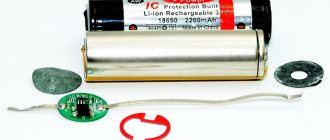
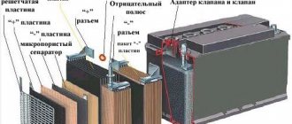
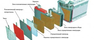
Lithium battery device
This article discusses the most promising lithium-ion batteries.
Lithium battery device
The electrodes of modern batteries are made by applying cathode material to aluminum foil (cathode) and, accordingly, anode material to copper foil. The chemical composition of the cathode material most often includes lithium salts of cobalt acid and solid solutions of lithium salts of nickel acid. Lithium salts of phosphoric acid are used as anode material. The electrolyte is a gel-like mass containing lithium salts. So-called separators - structures with a porous structure - are impregnated with electrolyte. Electrodes and separators are placed in a sealed housing. Connecting terminals are provided for current collection.
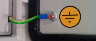
Lithium battery installation
Table of values of long-term permissible direct current depending on the cross-section of the copper cable at a voltage of 12 Volts and a temperature of 60 C.
Before installing the battery, you must make sure that the selected charging profiles and discharge current correspond to its characteristics. If this is not the case, the BMS will simply disconnect the battery for safety reasons. If you plan to charge a lithium battery from a car alternator, especially on EURO 6 cars, you must use a special charger.
Instead of the car body as a negative conductor, it is better to use a cable running from the negative terminal of the service battery to the negative terminal of the starting battery.
All cables connected to the lithium battery must be protected by fuses installed as close to the battery terminal as possible. The fuse rating should be 30% greater than the maximum current expected in the circuit. For example, if a 60 A charger is connected to a lithium battery with a capacity of 100 Ah, then 80 A fuses are placed at the input and output of the device
Ask a question,
and get advice on electrical equipment for a boat, yacht, motorhome or camper