What is a thermal relay?
The relay is called thermal because of its principle of operation, much like the principle of operation of an automatic switch, in which bimetallic plates, heated by electric current, break the circuit and put pressure on the release mechanism.
Since the thermal relay in the circuits must be connected behind the magnetic starter, there is no need to duplicate the contactor function after opening the circuits in emergency situations. Choosing such protection allows you to achieve significant savings in material for power contact groups. After all, it is much easier to switch small currents of a single control circuit than to break three contacts at once under a high current load.
Tip No. 1: When connecting the device, you should remember that the thermal relay does not break the power circuits directly; they are supplied with a control signal when the load increases.
Typically, the design of thermal relays provides for the presence of two contacts:
- normally closed;
- open in normal position.
After the relay is triggered, both of these contacts simultaneously change their position.
Purpose and principle of operation
When electric motors are overloaded, the current consumption increases and, accordingly, its heating increases. If the engine overheats, the integrity of the winding insulation is compromised, the bearings wear out faster, and they can jam. In this case, the thermal release of the machine may not protect the equipment. For this you need a thermal relay. Overloads can occur due to phase imbalance, difficult rotor movement, due to both increased mechanical load and problems with bearings, when the motor shaft and actuators are completely jammed.
The thermal relay reacts to the increased current and, depending on its value, will break the power circuit after some time, thereby keeping the motor windings intact. After subsequent elimination of the malfunction, provided the stator is in good condition, the engine can continue to operate.
If the relay has worked for unknown reasons, and inspection shows that everything is in order, you can return the relay contacts to their original state; there is a button on it for this. The relay can also operate in the event of a prolonged start of the electric motor. At the same time, increased current values flow in the windings. A slow start is a process when the engine takes a long time to reach its rated speed. This may occur due to an overload on the shaft, or due to low voltage in the supply network.
Interesting material to familiarize yourself with: what you need to know about the design of a power transformer.
Conclusions and useful video on the topic
The design and principle of operation of a current relay for effective protection of an electric motor using the example of the RTT 32P device:
Proper protection against overload and phase failure is the key to long-term trouble-free operation of an electric motor. Video about how the relay element reacts in the event of abnormal operation of the mechanism:
How to connect a thermal protection device to an MP, circuit diagrams of an electrothermal relay:
Thermal overload protection relay is a mandatory functional element of any electric drive control system. It reacts to the current passing to the motor and is activated when the temperature of the electromechanical installation reaches its limit values. This makes it possible to maximize the service life of environmentally friendly electric motors.
Please write comments in the block below. Tell us how you selected and configured a thermal relay for your own electric motor. Share useful information, ask questions, post photographs related to the topic of the article.
Principle of operation
The relay contains a pair of bimetallic plates with different temperature expansion coefficients. The plates are rigidly connected to each other; if they are heated, the structure will bend towards the area with a lower temperature coefficient of expansion. The plates are heated due to the flow of load current or from a heater through which the load current passes, shown in the diagram as several turns around the bimetal. The flowing current heats the plate to a certain limit. The higher the current, the faster the heating.
Thermal relay device
It is worth considering that if the relay is located in a hot room, you need to set the operating current with a large margin, because additional heating occurs from the environment. In addition, if the relay has just tripped, the contacts need some time to cool down. Otherwise, repeated false alarms may occur. Let's look at a specific example. Above you see the TRN relay device. It is two-phase. It consists of three cells, in the outermost there are heating elements, in the middle there is a temperature compensator, an operating current regulator, a release, a break contact, and a reset lever.
Generations of thermal relays
Design and principle of operation of the TR
Structurally, a standard electrothermal relay is a small device that consists of a sensitive bimetallic plate, a heating coil, a lever-spring system and electrical contacts.
A bimetallic plate is made from two dissimilar metals, usually Invar and chromium-nickel steel, firmly joined together by a welding process. One metal has a higher temperature coefficient of expansion than another, so they heat up at different rates.
During a current overload, the unfixed part of the plate bends towards the material with a lower coefficient of thermal expansion. This exerts a force on the contact system in the protective device and activates shutdown of the electrical installation in case of overheating.
Most models of mechanical thermal relays have two groups of contacts. One pair is normally open, the other is permanently closed. When the protective device is triggered, the state of the contacts changes. The first ones close, and the second ones become open.
The current is detected by an integrated transformer, after which the electronics processes the received data. If the current value is currently greater than the setting, the pulse is instantly transmitted directly to the switch.
By opening the external contactor, the relay with an electronic mechanism blocks the load. The thermal relay itself for the electric motor is installed on the contactor.
The bimetallic strip can be heated directly - due to the influence of the peak load current on the metal strip or indirectly, using a separate thermoelement. Often these principles are combined in one thermal protection device. With combined heating, the device has better performance characteristics.
Types of thermal relays
Thermal relays can be connected to all three phases or two of the three, depending on the design. Most relays are designed to fit specific magnetic starters for ease of installation and accuracy. Let's look at some of them.
- RTL – suitable for use with PML type starters. With a set of terminals, the KRL is used as an independent protection device.
- PTT – suitable for installation with PME and PMA starters. It can also be used as a standalone if mounted on a special panel.
- RTI – thermal relays for KMI and KMT starters. On the front you can see a couple of additional block contacts for implementing display circuits and other things.
- TRN – two-phase thermal relay. It is installed in three-phase motors, and is connected to a gap between two phases. Ambient temperature does not affect its operation. The current regulator has 10 divisions, 5 for decreasing, 5 for increasing, the price of one division is 5%.
In fact, there are a great variety of thermal relays, but they all perform one function. Relays are often mounted in a special iron box. In the photo there is a 4th size PMA starter for 63 Amperes, with a three-phase thermal relay. The thermal relay is connected to modern starters as shown in the photo below, resulting in a one-piece design.
Operating principle of a thermal relay
The most widely used designs are those in which the main element is a special bimetallic plate .
The latter is made of two metal layers with different temperature linear expansion coefficients. Due to this, when heated, it deforms (bends) and closes the contacts using a special lever. As a rule, for the manufacture of such plates, Invar is used in conjunction with chromium-nickel or non-magnetic steel.
Since this process is carried out smoothly, the occurrence of an electric arc between the approaching contacts is inevitable.
To prevent their burnout and the formation of carbon deposits, a “jumping” contact is used, which operates sharply after reaching critical parameters.
The plate itself is heated by the current passing through it or by a heater located nearby in the form of a spiral. A combined scheme is often used. In any case, the heating temperature is directly proportional to the current consumed by the electrical equipment.
After the relay is triggered, depending on the design, it returns to its original state either automatically, as it cools down, or using the appropriate switch (button).
Scope of application
One of the most important conditions for the profitable operation of an enterprise is the durability of the electrical equipment used. It depends on the conditions in which electrical installations have to operate. If equipment is often subjected to current overloads, then it is better not to hope for its long-term and reliable operation. After all, electrical equipment can operate for a long time only if rated currents flow through it. Excessive current (overload) leads to an increase in equipment temperature and premature aging of the insulation.
Types of thermal relays
To protect electric motors from current overload, thermal or thermal relays are successfully used in production. The most widely used relay is a bimetallic plate, which consists of two plates made of different metals that have different coefficients of thermal expansion. These plates are fastened together by hot rolling or welding. When a bimetallic strip is heated, it bends, as one metal expands more and the other less. The operation of a thermal relay is based on this principle. The greater the difference in temperature coefficients between metals, the more suitable they are for use in a bimetallic strip. The best options for different linear expansion today are: non-magnetic steel - copper, nickel - steel, brass - Invar.
We recommend: DIY wooden swing gates
Typically, the bimetallic strip is heated by the load current flowing through it. There are also models in which the plate is heated by a special heating element through which the load current flows. But combined heating is considered the best: both the load current through the plate and the heat from the heating element, through which the load current also flows. The heat-bent plate acts on the relay contacts. However, given that the bending of the plate occurs rather slowly, and as a result, when the contacts open, an electric arc will form, an accelerating device is provided in the relay design. The best of them is the “jumping contact”.
Dust-splash-proof thermal relay
The relay is returned to its original state using a special button or (in other models) spontaneously after cooling the bimetallic plate. Certain versions of thermal relays can protect electrical equipment from current asymmetry in different phases and from the loss of one of the phases. The actuator of the thermal relay is, as a rule, a magnetic starter. The relays can be installed either inside the starter or on a standard mounting rail. The range of rated currents of thermal elements is very large and ranges from 1 to 600 amperes.
When choosing a thermal relay, you should be guided by the rated load current (usually an electric motor). Typically, the thermal relay current is 20-30% greater than the rated current of the motor, since the relay operates within 20 minutes if the current is 1.2-1.3 times higher than the operating value. It is also necessary to take into account the heating time, since during a short-term overload, only the motor winding heats up, and during a long-term overload, the entire housing is heated. Therefore, it is rational to use a thermal relay in cases where the operating cycle of the equipment is more than half an hour.
It is also necessary to take into account the ambient temperature in which the thermal relay will operate, since as the ambient temperature increases, the operating current of the thermal relay decreases. If in the room where the protected electrical equipment is installed, the ventilation in the summer cannot cope with maintaining normal temperature, it is necessary to adjust the thermostat or select another heating element for it. Naturally, the thermal relay must be installed in the same room where the protected object is installed. You should strictly avoid proximity to concentrated heat sources (heating systems, heating stoves, etc.).
Thermal relay contacts
Thermal relays RTT, TRN, RTL
Thermal relays
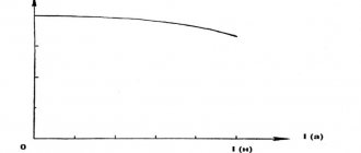
Thermal relay is an electrical device designed to protect an electric motor from current overloads. The most common types of thermal relays are TRN, TRP, RTT and RTL. The service life of electrical equipment largely directly depends on the overloads affecting it during operation of the equipment. For any equipment, it is quite simple to find the dependence of the time of current flow on its value, at which long-term and reliable operation of the equipment is achieved. At rated currents, the permissible time of its flow is infinity. The flow of currents greater than the rated one leads to an increase in operating temperatures and a significant reduction in service life, primarily due to insulation wear. As a result, the greater the overload, the shorter the time of their impact should be. Ideal equipment protection - the dependence tср (I) for thermal relays passes below the curve for the protected equipment. The most widely used thermal relay with a bimetallic plate for overload protection. The bimetallic plate used in a thermal relay consists of plates having different temperature expansion coefficients (one is larger, the other is smaller). At the contact points, the plates are rigidly attached to each other by hot rolling or welding. When a stationary bimetallic plate is heated, it bends towards the part with a lower expansion coefficient. It is this property that is used when operating a thermal relay. Also widely used are plates consisting of invar (lower coefficient) and chromium-nickel or non-magnetic steel (higher coefficient). Heating of the thermal relay plate occurs due to the heat generated when the load current flows through the bimetallic plate. Often a heating element is used, through which the load current also flows. The best characteristics have combined thermal relays, in which the load current flows through both the bimetallic plate and the heating element. When heated, the bimetallic plate of thermal relays acts on the contact system with its free part. Time-current characteristics of thermal relays The main characteristic for all thermal relays is the dependence of the shutdown time on the load currents (time-current characteristics). Before the overload begins, in the general case, a current Iо flows through the thermal relay, heating the bimetallic plate to the initial temperature qо. When checking the response time characteristics of a thermal relay, it is necessary to take into account whether the thermal relays operate in a cold or hot state. It is also necessary to remember that the heating element of a thermal relay is thermally unstable when short circuit currents flow. Selecting a thermal relay. The rated current of the selected thermal relay is selected based on the rated loads of the protected equipment (electric motor). The current of the selected thermal relay should be 1.2 - 1.3 of the rated current of the electric motor (load current), that is, the thermal relay is activated at 20 - 30% overload for 20 minutes. The heating time of the electric motor directly depends on the duration of the overload. In the event of a short-term overload, only the motor windings heat up and the heating time ranges from 5 to 10 minutes. During prolonged overloads, the entire engine structure is involved in heating, and the time ranges from 40 to 60 minutes. Therefore, it is considered most appropriate to use a thermal relay in circuits where the motor on time exceeds 30 minutes. The influence of external temperatures on the operation of a thermal relay. The heating of the bimetallic plate of a thermal relay depends both on the acting currents, but also on the influence of ambient temperature. In this regard, as the ambient temperature increases, the value of the operating current decreases. If the temperature differs greatly from the nominal temperature, a planned additional adjustment of the thermal relay is carried out, or a heating element is selected that takes into account the ambient temperature. To reduce the impact of ambient temperature on the operating currents of thermal relays, it is necessary to select the closest operating temperature. To ensure proper operation and provide thermal protection, the thermal relay must be placed in the same room as the protected mechanism (electric motor). It is not advisable to place the thermal relay in close proximity to heat sources, such as heating furnaces, heating systems, etc. Currently, temperature compensated relays (TRN series) are used to provide the best protection. Thermal relay design. The bending of the bimetallic plate occurs quite slowly. If a moving contact is directly connected to the plate, then the low speed of movement does not ensure the extinguishing of the arc that occurs when the circuit opens. Therefore, the impact on the contact is carried out through an acceleration device. The most effective is the so-called “jumping” contact. At the moment when voltage is not applied, the spring creates a moment relative to the zero point of the closing contact. When heated, the bimetallic plate bends, which leads to a change in the position of the spring. The spring creates a moment that is capable of opening the contact in a time that ensures reliable extinguishing of the arc. Starters and contactors are equipped with single-phase thermal relays of the TRP type or two-phase TRN relays. Thermal relays TRP Current single-pole thermal relays TRP with a rated current of the thermal element from 1 to 600 A used to protect three-phase asynchronous electric motors from thermal overloads operating in a network with a voltage of 500 V and a frequency of 50 or 60 Hz. Thermal relay TRP with a rated current of up to 150 A is used in direct current networks and voltages up to 440 V. Thermal relays RTL Thermal relay type RTL is used to protect equipment from long-term current overloads. They are also used to protect against current asymmetry in phases as well as loss of one phase. The operating current range of the RTL electrothermal relay is from 0.1 to 86 A. RTL thermal relays are installed both on PML type starters and separately; in this case, the relay must be equipped with KRL terminal blocks. The degree of protection of RTL relays and KRL terminal blocks can be IP20 and can also be installed on a standard DIN rail. The rated current of the contactor is 10 A. Thermal relay PTT The thermal relay PTT is designed to protect a three-phase asynchronous electric motor with a squirrel-cage rotor from short-term overload, including phase failure and imbalance. The thermal relay RTT is intended as a component in the control circuit of electric drives and integration into a magnetic starter of the PMA type in alternating current circuits with a voltage of 660 V and a frequency of 50 or 60 Hz, and in direct current circuits with a voltage of 440 V.
… → Relays → Thermal relays RTT, TRN, RTL →
Sort by default by name
all at once forward→
Thermal relay RTL 2063 In=80A
Thermal relay RTL 2061 In=80A
Thermal relay RTL 2059 In=80A
Thermal relay RTL 2057 In=80A
Thermal relay RTL 2055 In=80A
Thermal relay RTL 2053 In=80A
Thermal relay RTL 1022 In=25A
Thermal relay RTL 1021 In=25A
Thermal relay RTL 1016 In=25A
Thermal relay RTL 1014 In=25A
Thermal relay RTL 1012 In=25A
Thermal relay RTL 1010 In=25A
Thermal relay RTL 1008 In=25A
Thermal relay RTL 1007 In=25A
Thermal relay RTL 1006 In=25A
Thermal relay RTL 1005 In=25A
Thermal relay RTL 1004 In=25A
Thermal relay RTL 1003 In=25A
Thermal relay RTL 1002 In=25A
Thermal relay RTL 1001 In=25A
Thermal relay PTT 3 In=160A
Thermal relay PTT 3 In=125A
Thermal relay PTT 3 In=100A
Thermal relay PTT 3 In=80A
all at once forward→
Relay design
The control circuit relay consists of a temperature-sensitive element and a plurality of contact points. The control circuit for the protected computer passes through the relay contacts. If the machine is overloaded at current levels, the relay's thermal sensor switches to the thermal overload relays, which in turn send a signal to the machine's main power supply.
The term "sensing element" describes the number of individual circuits controlled by the switch. The number of wires determines the number of evaporator contacts. Heat relay switches usually have one to four poles - stinol, , .
The trigger mechanism actuates the thermal abb relay auxiliary switch, which breaks the coil circuits leading to the kmi engine contactor. At this moment, the indicator machine shows: “It worked.”
Magnetic starter connection diagram
How to choose a relay
Buyers can select and install a relay, taking into account its scope and the presence of certain mechanisms (functions):
- Thermal single-phase current relay with automatic reset will return to its original "closed" position after a certain period of time. If the motor is still overloaded after reset, the relay will operate again.
- The ambient temperature compensated relay operates effectively over a wide range of ambient temperatures.
- Some relays have varying degrees of phase control. These mechanisms can check the motor for phase loss from the contactor, rotation, or imbalance. At any stage of detection of problems, the relay ensures that the power supply to the engine is stopped. Phase imbalance in particular can cause dangerous fluctuations in motor voltage or current, resulting in motor damage.
- Underload refers to the relay's ability to detect a decrease in current as a result of unloading. This can happen if, for example, the pump starts to run dry. These relays are designed to detect these differences and travel as if detecting an overload.
- Relays with visual indicators are technical products that have light-emitting diodes (LEDs) or signaling sensors for status and connections.
The average price list (price) for a thermal relay is from 500 rubles to several thousand. It all depends on who the manufacturer is, the throughput level and the maximum ampere ratings. Therefore, read the description very carefully; it is provided in any catalog or store, so as not to buy a device that is too weak for your needs. GOST and passport are especially important; there you can find all the information you need. In some cities (Ekaterinburg, Moscow, Minsk and almost throughout Ukraine), you can buy TR directly from the factory at a reduced price.
Before connecting the relay, be sure to review the detailed instructions and, if possible, use the services of a professional (if you do not have such experience). Repairs are carried out only if you have special equipment and the necessary knowledge, otherwise we strongly recommend contacting a service center.
Connection diagram
Schemes for connecting a thermal relay to a circuit can differ significantly depending on the device. However, TPs are connected in series with the motor winding or magnetic starter coil to a normally open contact, because This type of connection allows you to protect the device from overloads. If the current consumption indicators are exceeded, the TR disconnects the device from the power supply.
In most connection schemes, a permanently open contact is used, which operates when connected in series with the stop button on the control panel. Basically, this contact is marked with the letters NC or H3.
A normally closed contact can be used when connecting an alarm about protection activation. In addition, in more complex circuits, this contact is used to implement software control of an emergency stop of the device using microprocessors and microcontrollers.
The thermostat is quite easy to connect. To do this, you need to be guided by the following principle: the TP is located after the starter contactors, but in front of the electric motor, and the permanently closed contact is switched on by a serial connection with the stop button.
Adjusting the thermal relay
To effectively perform the function of shutting down an electric motor or other serviced device, it is necessary to correctly adjust the TP settings so that the likelihood of false alarms is eliminated. It is recommended to carry out the adjustment on a specialized stand using fictitious loads:
- Current is passed through the temperature sensing element to simulate a real thermal load.
- Using a timer, the response time is determined. When adjusting using a control screw at a current of 1.5 In, the response time should be no more than 2.5 minutes, 5-6 In - no more than 10 seconds.
We recommend: Production and export of lumber
Installation features
As a rule, the thermal relay is installed together with a magnetic starter, which switches and starts the electric drive. However, there are also devices that can be installed as a separate device side by side on a mounting panel or DIN rail, such as TRN and PTT. It all depends on the availability of the required denomination in the nearest store, warehouse or garage in “strategic reserves”.
The presence of only two incoming connections for the TRN thermal relay should not scare you, since there are three phases. The unconnected phase wire goes from the starter to the motor, bypassing the relay. The current in the electric motor changes proportionally in all three phases, so it is enough to control any two of them. The assembled structure, the starter with the TRN heater will look like this:
Or like this with RTT:
The relays are equipped with two groups of contacts, a normally closed and a normally open group, which are labeled on the body 96-95, 97-98. The picture below shows a block diagram of the designation according to GOST:
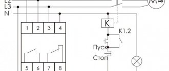
Let's figure out how to assemble a control circuit that would disconnect the motor from the network in the event of an overload or phase loss emergency. From our article about connecting a motor via a magnetic starter, you have already learned some nuances. If you haven’t had a chance to check it out yet, just follow the link.
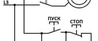
Let's consider the diagram from the article in which a three-phase motor rotates in one direction and the switching control is carried out from one place with two STOP and START buttons.
The machine is turned on and voltage is supplied to the upper terminals of the starter. After pressing the START button, the starter coil A1 and A2 is connected to the network L2 and L3. This circuit uses a starter with a 380-volt coil; look for a connection option with a single-phase 220-volt coil in our separate article (link above).
The coil turns on the starter and additional contacts No(13) and No(14) are closed, now you can release START, the contactor will remain on. This scheme is called “self-retaining start”. Now, in order to disconnect the engine from the network, you need to de-energize the coil. Having traced the current path according to the diagram, we see that this can happen when STOP is pressed or the contacts of the thermal relay are opened (highlighted by a red rectangle).
That is, if an emergency situation arises and the heater operates, it will break the circuit circuit and remove the starter from self-retaining, de-energizing the engine from the mains. When this current control device is triggered, before restarting it is necessary to inspect the mechanism to determine the cause of the shutdown, and not turn it on until it is eliminated. Often the cause of operation is high external ambient temperature; this point must be taken into account when operating the mechanisms and setting them up.
The scope of application of thermal relays in the household is not limited only to homemade machines and other mechanisms. It would be correct to use them in a heating system pump current control system. The specificity of the operation of the circulation pump is that limescale deposits form on the blades and scroll, which can cause the motor to jam and fail. Using the above connection diagrams, you can assemble a pump control and protection unit. It is enough to set the required rating of the heater in the power circuit and connect the contacts.
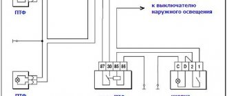
In addition, it will be interesting to see a diagram for connecting a thermal relay through current transformers for powerful motors, such as a pump for a water irrigation system for holiday villages or farms. When installing transformers in the power circuit, the transformation ratio is taken into account, for example, 60/5 is when the current through the primary winding is 60 amperes, on the secondary winding it will be equal to 5A. The use of such a scheme allows you to save on components without losing performance characteristics.
As you can see, the current transformers are highlighted in red, which are connected to the control relay and ammeter for visual clarity of the processes taking place. The transformers are connected in a star circuit, with one common point. Such a scheme does not pose any great difficulties in implementation, so you can assemble it yourself and connect it to the network.
Finally, we recommend watching a video that clearly shows the process of connecting a thermal relay to a magnetic starter to protect the electric motor:
That's all you need to know about connecting a thermal relay with your own hands. As you can see, installation is not particularly difficult, the main thing is to correctly draw up a diagram for connecting all the elements in the circuit!
Selection method
To correctly select the rating of a thermal relay, we need to know its In (operating, rated current) and, based on this data, we can select the correct setting range of the device.
The technical operation rules of the Electrical Installation Code stipulate this point and it is allowed to set up to 125% of the rated current in explosion-proof rooms, and 100%, i.e. not higher than the motor rating in explosive areas.
How to find out In? This value can be found in the electric motor’s passport or in the plate on the housing.
As you can see on the plate (click on the picture to enlarge) two ratings are indicated: 4.9A/2.8A for 220V and 380V. According to our connection diagram, you need to select the amperage, focusing on the voltage, and according to the table, select a relay to protect the electric motor with the desired range.
For example, let's look at how to choose thermal protection for an AIR 80 asynchronous motor with a power of 1.1 kW, connected to a three-phase 380 volt network. In this case, our In will be 2.8A, and the permissible maximum current of the “heater” will be 3.5A (125% of In). According to the catalog, RTL 1008-2 with an adjustable range of 2.5 to 4 A is suitable for us.
Connection, adjustment and marking
The overload switching device, unlike an electrical circuit breaker, does not break the power circuit directly, but only sends a signal to temporarily shut down the facility in emergency mode. Its normally switched contact works as a contactor “stop” button and is connected in a series circuit.
Device connection diagram
In the relay design, there is no need to repeat absolutely all the functions of the power contacts upon successful operation, since it is connected directly to the MP. This design allows for significant savings in materials for power contacts. It is much easier to connect a small current in the control circuit than to immediately disconnect three phases with a large one.
In many schemes for connecting a thermal relay to an object, a permanently closed contact is used. It is connected in series with the “stop” button of the control panel and is designated NC - normally closed, or NC - normal connected.
An open contact with such a scheme can be used to initiate the operation of thermal protection. Connection diagrams for electric motors in which a thermal protection relay is connected may vary significantly depending on the presence of additional devices or technical features.
In a standard simple circuit, the TP is connected to the output of a low-voltage starter on an electric motor. Additional contacts of the device must be connected in series with the starter coil
This will provide reliable protection against electrical equipment overloads. In case of unacceptable excess of current limit values, the relay element will open the circuit, instantly disconnecting the MP and the engine from the power supply.
The connection and installation of a thermal relay, as a rule, is carried out together with a magnetic starter designed for switching and starting an electric drive. However, there are types that are mounted on a DIN rail or a special panel.
We recommend: How to putty drywall: seams, corners, preparation for wallpaper, painting
Subtleties of adjusting relay elements
One of the main requirements for electric motor protection devices is the precise operation of the devices in the event of emergency operation of the motor. It is very important to select it correctly and adjust the settings, since false positives are absolutely unacceptable.
An electrothermal relay, which is optimally suited to a specific type of engine in all technical parameters, is capable of providing reliable protection against overloads in each phase, preventing a prolonged start of the installation, and preventing emergency situations with jamming of the rotor
Among the advantages of using current protection elements, one should also note a fairly high speed and a wide response range, and ease of installation. To ensure timely shutdown of the electric motor during overload, the thermal protection relay must be configured on a special platform/stand.
In this case, inaccuracy due to the natural uneven spread of rated currents in the NE is eliminated. To test the protective device on a bench, the fictitious load method is used.
A reduced voltage electric current is passed through the thermocouple to simulate the actual thermal load. After this, the exact time of operation is accurately determined using the timer.
When setting up basic parameters, you should strive for the following indicators:
- at 1.5 times the current, the device should turn off the engine after 150 s;
- at 5...6 times the current it should turn off the motor after 10 s.
If the response time is not correct, the relay element must be adjusted using the control screw.
For correct operation, it is necessary to set the device to the highest permissible electric current of the motor and air temperature
This is done in cases where the rated current values of the NE and the motor differ, as well as if the ambient temperature is below the nominal one (+40 ºC) by more than 10 degrees Celsius.
The operating current of the electrothermal switch decreases with increasing temperature around the object in question, since the heating of the bimetallic strip depends on this parameter. If there are significant differences, it is necessary to further adjust the thermocouple or select a more suitable thermoelement.
Sharp temperature fluctuations greatly affect the performance of the current relay. Therefore, it is very important to choose a NE that can effectively perform basic functions, taking into account real values.
It is recommended to place the TR in the same room as the protected electrical installation. They should not be installed close to heat generators, heating furnaces and other heat sources.
These restrictions do not apply to temperature compensated relays. The current setting of the protective device can be adjusted in the range of 0.75-1.25x from the rated current of the thermoelement. The setup is done in stages.
First of all, the correction E1 is calculated without temperature compensation:
E1=(Inom-Ine)/c×Ine,
Where
- In – rated motor load current,
- Ine – rated current of the working heating element in the relay,
- c is the price of the scale division, that is, the eccentric (c=0.055 for protected starters, c=0.05 for open ones).
The next step is to determine the E2 correction for ambient temperature:
E2=(ta-30)/10,
Where ta (ambient temperature) is the ambient temperature in degrees Celsius.
The last stage is finding the total correction:
E=E1+E2.
The total correction E can be with a “+” or “-” sign. If the result is a fractional value, it must be rounded down to a whole number downwards/larger in magnitude, depending on the nature of the current load.
To adjust the relay, the eccentric is transferred to the resulting value of the total correction. A high response temperature reduces the dependence of the operation of the protective device on external indicators.
The thermal protection relay allows manual smooth adjustment of the device's operating current within ±25% of the rated current of the electromechanical installation
The adjustment of these indicators is carried out by a special lever, the movement of which changes the initial bend of the bimetallic plate. The operation current can be adjusted over a wider range by replacing the thermoelements.
Modern overload protection switching devices have a test button that allows you to check the serviceability of the device without a special stand. There is also a key to reset all settings. They can be reset automatically or manually. In addition, the product is equipped with an indicator of the current state of the electrical appliance.
Marking of electrothermal relays
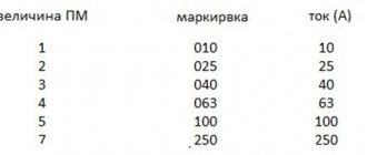
Protective devices are selected depending on the power of the electric motor. The main part of the key characteristics is hidden in the symbol.
This is what the marking of thermal relays from the KEAZ plant looks like. When choosing, it is important to pay attention to the rated current of the model in question so that it is sufficient
You should focus on certain points:
- The range of setting current values (indicated in parentheses) varies minimally among different manufacturers.
- The letter designations for a specific type of execution may vary.
- Climatic performance is often presented in the form of a range. For example, UHL3O4 should be read as follows: UHL3-O4.
Today you can buy a variety of device variations: relays for alternating and direct current, monostable and bistable, devices with deceleration when turned on/off, thermal protection relays with accelerating elements, thermal protection relays without a holding winding, with one winding or several.
These parameters are not always displayed in the labeling of devices, but must be indicated in the data sheet of electrical products.
The following article will introduce you to the structure, types and markings of an electromagnetic relay, which we recommend that you read.
Types of thermal protection relays
There are several types of relays to protect electric motors from phase failure and current overloads. They all differ in design features, the type of MP used and their use in different motors.
TRP . Single-pole switching device with combined heating system. Designed to protect asynchronous three-phase electric motors from current overloads. TRP is used in DC power networks with a base voltage under normal operating conditions of no more than 440 V. It is resistant to vibrations and shocks.
RTL . Provide engine protection in the following cases:
- when one of the three phases fails;
- asymmetry of currents and overloads;
- delayed start;
- jamming of the actuator.
They can be installed with KRL terminals separately from magnetic starters or mounted directly on the PML. Installed on standard type rails, protection class – IP20.
PTT . They protect asynchronous three-phase machines with a squirrel-cage rotor from a delayed start of the mechanism, prolonged overloads and asymmetry, that is, phase imbalance.
TRN . Two-phase switches that control the start-up of an electrical installation and the operating mode of the motor. They are practically independent of the ambient temperature; they only have a system for manually returning the contacts to their initial state. They can be used in DC networks.
RTI . Electric switching devices with constant, albeit small, electricity consumption. Mounted on contactors of the KMI series. Work together with fuses/circuit breakers.
Solid state current relays . They are small three-phase electronic devices with no moving parts.
They operate on the principle of calculating the average values of engine temperatures, for this purpose constantly monitoring the operating and starting current. They are impervious to changes in the environment, and therefore are used in hazardous areas.
RTK . Starting switches for temperature control in electrical equipment housings. They are used in automation circuits where thermal relays act as components.
Installation errors
- The main mistake of inexperienced craftsmen is purchasing and installing a relay with parameters that do not match the parameters of the electric motor. You must carefully read the description of the product and its characteristics given in the device passport.
- Also, when selecting and installing a relay, the outside air temperature during operation of the device is often not taken into account. Too high a temperature may cause frequent triggering.
- Another serious mistake is tightening the device contacts too tightly with a screwdriver. When performing this work, care should be taken not to damage the relay.
Sources
- https://electric-tolk.ru/podklyuchenie-teplovogo-rele/
- https://ElectroInfo.net/radiodetali/chto-takoe-teplovoe-rele.html
- https://www.asutpp.ru/teplovoe-rele.html
- https://odinelectric.ru/equipment/printsip-raboty-i-shema-podklyucheniya-teplovogo-rele
- https://www.RadioElementy.ru/articles/skhema-podklyucheniya-teplovogo-rele/
- https://elektrik-sam.ru/jelektrooborudovanie/rele-kontaktory-datchiki/3970-kak-samostojatelno-podkljuchit-teplovoe-rele-obzor-shem.html
- https://sovet-ingenera.com/elektrika/rele/teplovoe-rele.html
How do you like the article?
Sergey Vladimirovich
Ask a Question