Electrical properties and material characteristics (general)
Electric and magnetic fields do not exist separately (independently), because They give birth to each other. Electrical materials
Electrical materials are materials that have certain properties in relation to the electromagnetic field and are used in technology taking these properties into account (various materials are exposed to both individual electric and magnetic fields and their combination).
Application: electrical machines, devices, instruments and other elements of electrical equipment and electrical installations.
Classification of electrical materials.
1. In an electric field.
1. Conductor materials (conductors) are materials in which an electric current arises under the influence of an electric field (metals and their alloys, graphite).
Conductors contain free charge carriers and under the influence of an electric field they acquire directional movement. This ordered movement of electric charges is electric current.
Application: live parts of electrical machines, devices and networks.
2. Semiconductor materials (semiconductors) are materials in which an electric current arises under the influence of an eclectic field, but their conductivity depends on external conditions (temperature, impurities, light, electric and magnetic fields, pressure, nuclear radiation, etc.) (germanium Ge, silicon Si, silicon carbide SiC).
Application: electronic equipment (diodes, transistors, thyristors).
3. D- electric materials (dielectrics) are materials that, under the influence of an electric field, do not create an electric current under normal conditions, the main electrical property of which is the ability to polarize in an electric field (rubber, plastics, glass).
In dielectrics, electric charges are firmly bound to atoms, molecules or ions and in an electric field they can only shift, and the centers of positive and negative charges separate, i.e. polarization.
Application: insulation of live parts from each other, surrounding objects and personnel.
2. In a magnetic field.
1. Weakly magnetic materials are materials whose magnetic susceptibility is very low (copper Cu, aluminum Al, lead Pb, organic compounds).
Application: not widely used in technology.
2. Highly magnetic materials (magnets) are materials that are magnetized under the influence of a magnetic field and thereby strengthen it (iron Fe, nickel Ni, cobalt Co and their alloys).
Application: cores and magnetic circuits of electrical machines and devices, permanent magnets.
MECHANICAL PROPERTIES AND CHARACTERISTICS OF MATERIALS
Mechanical characteristics make it possible to evaluate the ability of materials to withstand external static and dynamic loads; they are necessary for selecting technological processing of materials (cutting, stamping, casting), strength calculations, monitoring and diagnosing the condition of structural parts during operation.
Tensile testing is carried out on cylindrical samples and bars with a rectangular cross-section. The sample is secured at its ends in the grips of the testing machine. The lower grip is stationary; a destructive tensile force is applied to the other, which is gradually increased at a certain speed until the sample breaks.
1. Plasticity is the property of a material to irreversibly change its shape and size under the influence of external mechanical loads.
Relative extension
where ∆lorest is the increment in sample length after rupture, mm;
l0 – initial sample length, mm.
The greater the elongation value, the more ductile the material.
2. Strength is the property of a material to resist deformation or destruction under the influence of external mechanical loads.
Breaking tensile stress (tensile strength)
where Рр – failure load upon rupture of the sample, N;
S0 – cross-sectional area of the sample before testing, mm2.
The higher the tensile strength value, the stronger the material.
3. Hardness is the property of a material to resist penetration of a harder body (indenter) into its surface.
An indenter is a carbide tip in the form of a ball, pyramid or cone, the hardness of which significantly exceeds the hardness of the material being tested.
Using the Brinell method, a steel ball is pressed into the surface of the material.
where P is the load on the indenter, N;
Stp – print surface area, mm2.
According to the Vickers method, a diamond tetrahedral pyramid is pressed into the surface of the material under the influence of a load.
The higher the hardness value, the harder the material.
4. Impact strength is the property of a material to resist impact loads.
The impact bending test is carried out on bars with a rectangular cross-section (for metals with a U-shaped and V-shaped notch). The sample is placed in a pendulum impact driver. The impact applied to the center of the sample by the pendulum is gradually increased. The pointer on the scale of the pile driver records the value of the work expended by the pendulum to destroy the sample.
where ∆A is the work expended by the pendulum to destroy the sample, MJ.
The higher the impact strength value, the less brittle the material is.
Electrical properties and material characteristics (general)
Electrical characteristics make it possible to evaluate the properties of materials when exposed to an electric field. The main property of electrical materials in relation to the electric field is electrical conductivity.
Electrical conductivity is the property of a material to conduct electric current under the influence of a constant (not changing over time) electrical voltage.
1. Electrical resistivity is the resistance of a material 1 m long and with a cross section of 1 m2.
where γ is the specific conductivity of the material, this is the conductivity of a material with a length of 1 m and a cross section of 1 m2, 1/Ohm∙m;
q – value of the charge of the carrier (electron charge 1.6·10-19), C;
n is the number of charge carriers per unit volume;
µ – charge carrier mobility.
The higher the ρ value, the lower the electrical conductivity of the material.
Conductors ρ=10-8÷10-6.
Semiconductors ρ=10-6÷108.
Dielectrics ρ=108÷1018.
Conductor resistance is a design characteristic of a conductor, because depends on the size and conductive properties of the material.
where ρ is the resistivity of the material, Ohm∙m;
l – conductor length, m;
S – cross-sectional area of the conductor, m2.
2. Temperature coefficient of resistivity - shows how much the resistance of a material in 1 Ohm will change when it is heated by 1 0C.
With a linear change in resistivity in a narrow temperature range
where ρ is the resistivity of the material at temperature;
ρ0 – resistivity of the material at initial
temperature t0, usually taken to be 200C.
If we replace resistivity with resistance
The larger the value of α, the more the resistance of the conductor changes with temperature changes.
Conductors α>0 with increasing temperature, the resistivity of the material increases.
Semiconductors and dielectrics α<0 with increasing temperature, the resistivity of the material decreases.
Classification of radio-electronic radio materials
Lecture 1. Purpose, basic properties and electrical characteristics of radio materials
Content
Lecture 1. Purpose, basic properties and electrical
characteristics of radio materials………………………………………………………..5
Lecture 2. Energy losses in dielectrics, mechanical,
thermal and physico-chemical characteristics of materials………………..7
Lecture 3. Electrical processes in dielectrics,
polarization, electrical conductivity and breakdown of dielectrics………………….12
Lecture 4. Types of solid dielectrics,
polymerization and polycondensation dielectrics…………………17
Lecture 5. Plastics, varnishes and compounds……………………………………………………….23
Lecture 6. Radioceramic materials, glasses and glass ceramics……………….28
Lecture 7. Piezoceramic materials and electrets……………………….32
Lecture 8. Conducting materials and wires……………………………..35
Lecture 9. Characteristics of magnetic materials……………………………..40
Lecture 10. Metallic magnetic soft and
magnetically hard materials……………………………………………………………..44
Lecture 11. Ferrites and magnetodielectrics……………………………………………………….47
Lecture 12. Semiconductor materials………………………………………………………. 51
Lecture content:
— classification of radio-electronic materials;
— basic electrical characteristics of materials.
Lecture objectives:
— study of the classification of radio materials;
— study of the basic electrical characteristics of materials.
Unlike structural (plastics, metals) and auxiliary (solders, adhesives) materials, electronic materials in devices, when exposed to electromagnetic fields, must perform their inherent functions. Some radio materials, for example, dielectrics, can be simultaneously exposed to high electrical voltage, direct and alternating currents. This causes a special state of stress in the material. The failure of even one of the dielectrics often entails the failure of the radio component in which this dielectric is used (capacitor, transformer, connector, etc.), and sometimes the entire device.
A very difficult task is the correct choice of material, determined primarily by the totality of its electrical, mechanical, magnetic, thermal and physicochemical properties. These properties are determined by quantities called characteristics or parameters of materials.
All radio materials can be divided into four main groups: conductors, semiconductors, dielectrics, and magnetic materials.
Conductors
— ϶ᴛᴏ metallic materials that have high electrical conductivity due to the presence of a large number of free electrons.
Dielectrics
— ϶ᴛᴏ materials with low electrical conductivity, because they have very few free charged particles (electrons and ions).
Semiconductors
— ϶ᴛᴏ materials that have lower electrical conductivity than conductors, because they have significantly fewer free electrons.
Magnetic
are called materials that, under the influence of an external magnetic field, are capable of magnetization, ᴛ.ᴇ. acquire magnetic properties, which is due to their structure.
Each of the radio materials has electrical properties, because All radio materials (including dielectrics) have electrical conductivity. Electrical characteristics are used to evaluate electrical properties.
Electrical resistivity ρ
— ϶ᴛᴏ electrical characteristic used to assess the electrical conductivity of materials. It is expressed in ohms per meter (Ohm m). In radio electronics, a smaller unit (Ohm cm) is also used. To assess the high electrical conductivity of metal conductor materials (copper, aluminum, etc.), an even smaller value of electrical resistivity is used - microohm per meter (µOhm m). The relationship between the listed units: 1 Ohm cm = 10,000 μOhm m = 0.01 Ohm m.
All radio materials can be divided into three main groups based on electrical conductivity:
conductors ρ = 10-8 ÷ 10-5 Ohm m,
semiconductors ρ = 10-6 ÷ 107 Ohm m,
dielectrics ρ = 107 ÷ 1018 Ohm m.
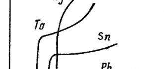
The electrical resistivity of any radio material depends on temperature (Figure 1.1-a). Thus, the electrical resistivity of conductors increases with increasing temperature. In semiconductors and dielectrics, on the contrary, with increasing temperature, the electrical resistivity decreases.
Temperature coefficient of resistivity
ТК
ρ
is a value with which you can take into account the change in electrical resistivity based on the temperature of the material ТК
ρ
= (
ρ
2 –
ρ
1) /
ρ
1(
Т
2 –
Т
1), where
ρ
1 and
ρ
2 - resistivity of the material at the initial
T
1 and final
T
2 temperatures.
For conductors, the resistivity increases with increasing temperature, ᴛ.ᴇ. TK ρ
> 0 is a positive value; for semiconductors and dielectrics, the resistivity decreases with increasing temperature, ᴛ.ᴇ.
TK ρ
< 0 – negative value.
a) b)
Figure 1.1 – Dependence of the electrical resistivity of materials on temperature (a), volumetric and surface electrical conductivity currents in the dielectric (b).
In solid dielectrics there are currents of volume IV and surface IS electrical conductivity (Figure 1.1-b), in connection with this, their specific volume ρ V and surface ρ S resistance are determined. Specific surface resistance, like total resistance, is expressed in ohms. Specific volume resistance characterizes the ability of a dielectric to conduct current through its volume, and specific surface resistance - along its surface. For dielectrics ρ V = 107÷ 1018 Ohm m; ρ S = 109 ÷ 1016 Ohm.
Conductivity
γ (S/m) – the reciprocal of resistivity γ = 1/
ρ
.
For solid dielectrics, a distinction is made between specific volume conductivity γ V = 1/ ρ V (S/cm, Ohm-1 m-1) and specific surface conductivity γ S = 1/ ρS
(S).
Specific conductivity characterizes the degree of electrical conductivity of a radio material. So, for conductors γ = 105 ÷ 108 S/m, and for semiconductors γ = 106 ÷ 10-7 S/m. The specific volume and surface conductivities of solid dielectrics are very small: γ V = 10-7 ÷ 10-18 S/m,
γ S = 10-8÷ 10-16 cm. This allows them to be used for insulating parts of radio-electronic devices that are under different electrical potentials.
To estimate the electrical resistance of thin films (dielectrics, semiconductors, etc.), for example, in thin-film integrated circuits, use the film resistance R
(Ohm /), related to the square of its surface (Figure 1.2-a):
R
=
ρ a /Δ a = ρ/Δ
.
Dielectric constant εr
(relative permittivity) characterizes the ability of a dielectric or semiconductor to form electrical capacitance.
The capacitance C
(F) of a flat capacitor (Figure 1.2-b) of given dimensions is directly proportional to the dielectric constant of the dielectric used in it
C = εаS/h
, where
εа
is the absolute dielectric constant, F/m,
S
is the area of one metal plate, m2 ,
h
– dielectric thickness, m;
εа = ε0 εr
, where
ε0
= 8.85416·10-12 – electric constant, F/m,
εr
– relative dielectric constant (dimensionless quantity).
εr
= 1), liquid and solid dielectrics (
εr
≈ 2÷17)
have the lowest dielectric constant dielectric constant of air εr
= 1.00058.
a) b)
Figure 1.2 – Measurement of electrical resistance of thin films (a), flat capacitor (b).
Temperature coefficient of dielectric constant
TC
εr
(K-1) characterizes the change in dielectric constant
εr of
radio materials from temperature (Figure 1.3-a):
ТКεr = ( εr1 - εr2
)
/εr1
(
T1 - T2
), where
εr
1 and
εr
2 are the dielectric constant of the material at the initial
T1
and final
T2
temperatures. The temperature coefficient of dielectric constant has a positive or negative value and, accordingly, indicates whether the dielectric constant of a given dielectric increases or decreases (with increasing temperature).