Types and meaning of lines
- Thin and thick solid lines - in the drawings depict electrical lines, group communication lines, lines on UGO elements.
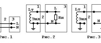
- Dashed line - indicates shielding of wire or devices; denotes a mechanical connection (motor - gearbox).
- Thin dash-dotted line - intended to highlight groups of several components that make up parts of a device or control system.
- A dot-dash line with two dots is a dividing line. Shows a breakdown of important elements. Indicates an object remote from the device that is connected to the system by mechanical or electrical communication.
Network connecting lines are shown in full, but according to the standards, they are allowed to be cut off if they interfere with the normal understanding of the circuit. The break is indicated by arrows; the main parameters and characteristics of the electrical circuits are indicated nearby.
A thick dot on the lines indicates a connection, soldering of wires.
Ground color
The color of the grounding wire, “ground”, is almost always indicated by yellow-green color
. Windings that are either completely yellow or light green are less common. The wire may be marked “PE”. You can also find green-yellow wires marked “PEN” and with blue braiding at the ends of the wire at the fastening points - this is grounding combined with neutral.
In the distribution panel (DP) it should be connected to the grounding bus, to the housing and the metal door of the panel. As for the distribution box, the connection goes to the grounding wires from the lamps and from the grounding contacts of the sockets. The ground wire does not need to be connected to the RCD (residual current device), therefore RCDs are installed in houses and apartments, since electrical wiring is usually carried out with only two wires
Grounding designation on the diagrams:
Conventional ground(1) Clean ground(2) Safety ground(3) Chassis ground(4) DC ground(5)
What is the difference between grounding
Wire color coding
Anyone who has ever dealt with wires and electricity has noticed that conductors always have different insulation colors. This was done for a reason
The colors of the wires in electrics are designed to make it easier to recognize the phase, neutral wire and ground. They all have a certain color and are easily distinguished during operation. The color of the phase, neutral, and ground wires will be discussed further.
How phase wires are painted
When working with wiring, phase wires pose the greatest danger. Touching the phase, under certain circumstances, can become lethal, which is probably why bright colors were chosen for them. In general, the colors of electrical wires allow you to quickly determine which of a bunch of wires are the most dangerous and work with them very carefully.
Coloring of phase wires
Most often, phase conductors are red or black, but other colors are also found: brown, lilac, orange, pink, purple, white, gray. Phases can be painted in all these colors. It will be easier to deal with them if you exclude the neutral wire and ground.
In the diagrams, phase wires are designated by the Latin (English) letter L. If there are several phases, a numerical designation is added to the letter: L1, L2, L3 for a three-phase 380 V network. In another version, the first phase is designated by the letter A, the second by B, and the third by C .
Ground wire color
By modern standards, the ground conductor is yellow-green. It usually looks like yellow insulation with one or two longitudinal bright green stripes. But there are also transverse yellow-green stripes in color.
Grounding may be this color
In some cases, the cable may only have yellow or bright green conductors. In this case, the “earth” has exactly this color. It is displayed in the same colors on diagrams - most often bright green, but it can also be yellow. Signed on circuit diagrams or on ground equipment in Latin (English) letters PE. The contacts to which the “ground” wire must be connected are also marked.
What color is the neutral wire?
Zero or neutral is blue or light blue, sometimes blue with a white stripe. Other colors are not used in electrical engineering to indicate zero. It will be like this in any cable: three-core, five-core or with a large number of conductors.
What color is the neutral wire? Blue or cyan
“Zero” is usually drawn in blue on diagrams and signed with the Latin letter N. Experts call it a working zero, since, unlike grounding, it participates in the formation of the power supply circuit. When reading a diagram, it is often defined as "minus", while the phase is considered "plus".
How to check the correctness of marking and wiring
Take a multimeter and/or an indicator screwdriver. It’s easy to work with a screwdriver: when you touch a phase, the LED built into the housing lights up. So it will be easy to identify phase conductors. If the cable is two-wire, there are no problems - the second conductor is zero. But if the wire is three-wire, you will need a multimeter or tester - with their help we will determine which of the remaining two is phase and which is zero.
Determining the phase wire using an indicator screwdriver
We set the switch on the device so that the selected jackal is more than 220 V. Then we take two probes, hold them by the plastic handles, carefully touch the metal rod of one probe to the found phase wire, the second to the supposed zero. The screen should display 220 V or the current voltage. In fact, it may be significantly lower - this is our reality.
If 220 V or a little more is displayed, this is zero, and the other wire is presumably “ground”. If the value is less, we continue checking. With one probe we again touch the phase, with the second - to the intended grounding. If the instrument readings are lower than during the first measurement, there is “ground” in front of you and it should be green. If the readings turn out to be higher, it means that somewhere there was a mistake with “zero” in front of you. In such a situation, there are two options: look for exactly where the wires were connected incorrectly (preferable) or simply move on, remembering or noting the existing position.
And, in conclusion, let me give you some advice: when laying wiring and connecting wires, always connect conductors of the same color, do not confuse them. This can lead to disastrous results - at best, equipment failure, but there may also be injuries and fires.
This is interesting: How to unscrew the valve axle box from the mixer if it is stuck?
What does L stand for?
Common symbols on light switches are applied to mark their contact connectors or to indicate the position in which their key is located.
Single-key switch connection diagram
Presumably, this symbol is taken from the first letter of the English word "Line", meaning line or linear wire. The second contact also has its own designation, which varies from manufacturer to manufacturer:
- The symbol L with a unit added to it is L1.
- The same sign, but with the addition of a stroke - L`.
- A small arrow pointing up.
- Just one (“1”).
A number of manufacturers do not indicate this outlet at all. If it is on top, a wire is led from it to the chandelier or junction box.
Connection diagram for two-button switch
The PUE stipulates from which sides conductors should be supplied and discharged to the switch. According to the requirements of the regulations, the connection is made from below, and the outlet is mounted from above.
For two-key and three-key devices, the number of output conductors increases to two and three, respectively, which forces their manufacturers to mark additional contacts. Therefore, their designations often contain icons such as L2, L3, or the same letter, but with two or three strokes. It is also possible that instead of letters next to the output terminals there are only numbers corresponding to the number of the output conductor.
How_the_phase_on_the_switch_is_designated
For different companies that produce electrical products, the standard designations on the contacts of light switches may not be the same. You should figure out what the L on the light switch means and whether there are any other symbols. This knowledge will help all interested parties, after purchasing the installation product, to correctly connect it to the current electrical network.
Connection features
To understand the connection features of a standard switch, you will need to study the principle of its operation. As an example convenient for description, a type of device with one key was chosen.
0:00 / 0:00
- Podcast
.
Philips marking
Let’s look at the marking of this company using the example of the well-known LED – Luxeon Rebel. Its marking: LXML-ABCD-EFGH
- LXML – series;
- A – type of light distribution (P for Lambertian distribution);
- B – emitted color (W – white, from the word White);
- C – white color (C – cold, N – neutral, W – warm);
- D – rated current (I for current 350 mA);
- E – digit reserved for future versions of LED;
- FGH – luminous flux measured in lumens.
For example, a white LED with a rated current of 350 mA will be labeled: LXML-PWxI-0xxx.
LED Luxeon of similar series have similar markings. In general terms, we can say that the marking of this diode is very informative in comparison with other manufacturers.
Species and types
Electrical wiring diagrams are special drawings that indicate certain connections between electrical elements and devices that are connected to the network and consume electricity. The connection is described and organized according to standards and rules that are defined and operate according to physical laws. The diagram is designed to teach electricians and other specialists to understand the principle of network structure and the structure of devices, what parts it consists of.
Important! The main purpose of electrical diagrams is to help install and configure electrical devices and make repairs based on quick and easy troubleshooting. To delve deeper into the topic, you should understand what types of wiring diagrams exist and by what principles they are divided, what their characteristic features are. Electrical circuits, like documents, are divided into several types and types, divided according to certain standards
First of all, you need to understand the main types of electrical circuits, which are:
Electrical circuits, like documents, are divided into several types and types, divided according to certain standards. First of all, you need to understand the main types of electrical circuits, which are:
To delve deeper into the topic, you should understand what types of wiring diagrams exist and by what principles they are divided, what their characteristic features are. Electrical circuits, like documents, are divided into several types and types, divided according to certain standards. First of all, you need to understand the main types of electrical circuits, which are:
- Structural. The simplest option, which in the simplest “words” makes it clear how this or that device works and what it consists of. The order of reading such documents is indicated by arrows from block to block, and incomprehensible points are indicated by explanatory inscriptions;
- Assembly. They are often used in manuals or online resources, where it is suggested that you install electrical wiring or other elements yourself. In such a diagram, you need to show the exact location of each individual element of the circuit (sockets in the house, and so on);
- United. As the name implies, this document combines several types and types of schemes. Typically, such electrical circuits are used in cases where all the important features of the circuit can be shown without a huge number of different elements;
- Layout diagrams. Documents defining the relative location of certain components of a product or electrical installation, and, if necessary, also bundles (wires, cables), pipelines, optical fibers, etc.;
- Are common. Those that define the parts that make up the complex, as well as their connections;
- Functional. They are not much different from structural ones, but they describe in more detail all the components and nodes of the network. They no longer have obvious connections and components;
- Principled. They are most often used in distribution networks, as they provide an accurate understanding of how a particular electrical equipment operates. On this kind of diagrams, all functional blocks of the circuit and the types of connections between them must be indicated;
- Connections. Original documents indicating methods of external connections of the device to other networks and other devices.
Complete schematic drawing
The specific feature of the schemes divides them into:
- Electrical. Documents showing the components of products powered by electrical energy;
- Gas. Papers that display the structure and main components of the gas system of any equipment, room, etc.;
- Hydraulic Documents showing the components of products and their structure, using the energy of compressed fluid for work;
Functional electrical diagram
- Division diagrams Design documents that determine the composition of the device, its components, their intended purpose and relationship;
- Pneumatic. Documents showing the components of products and their structure, using the energy of compressed gases for operation;
- Kinematic. Diagrams in which, using special symbolic drawings, the links of mechanisms and kinematic pairs are indicated for their kinematic analysis;
- Combined. With their help, the main and auxiliary equipment of a device or circuit, their interconnection and automation tools that show the technical process are displayed;
- Vacuum. Schemes that allow you to describe devices whose action (and their components) are based on changing pressure and achieving a vacuum;
- Optical. They represent the process of changing light in an optical system.
⇡ USB: devil logo
An image symbolizing a USB connection can be found on any cable or next to the connection socket. Created within the framework of the USB 1.0 specification, the USB port designation is presented in the form of a triple line, reminiscent of a fragment of a printed circuit. In a vertical position, this sign takes on the appearance of a trident, which is no coincidence.
The designers borrowed this symbol from the image of the god of the water element Neptune (Poseidon) in ancient mythology. In ancient Greek mythology, the mighty pitchfork of Poseidon has a special meaning - it is both a formidable weapon with which the god destroys rocks, and a symbol of power. As on the trident of Poseidon, the central point protrudes a little more, but if in Greek mythology this means the rod of Zeus and recognition of the power of the elder brother (the other two “teeth” on the trident of Poseidon are the spear of the second brother, Hades, the god of the underworld of the dead), then in the case of the USB logo, the protruding element has no meaning. Instead of spikes on the trident of the USB logo, three basic geometric shapes are drawn - a circle, a square and a triangle. These simple figures symbolize the variety of peripheral devices that can be connected to a single USB interface.
It's funny that the trident from the USB logo has become a point of contention among some believers. Four years ago, it caused a not entirely adequate reaction among some religious ministers in Brazil, who dubbed it a tool of the devil and urged users to abandon the benefits of this technology, using Firewire or Bluetooth instead. If we follow this strange Brazilian logic, then, following USB, we would need to ban all Apple products with a logo in the form of a bitten apple, and at the same time throw out dessert cake forks with three prongs. As they say, out of harm's way.
How to check the correctness of marking and wiring
Wire colors in electrical engineering are designed to speed up the identification of conductors, but relying only on colors is dangerous - they could be connected incorrectly. Therefore, before starting work, you should make sure that you have correctly identified their affiliation.
Take a multimeter and/or an indicator screwdriver. It’s easy to work with a screwdriver: when you touch a phase, the LED built into the housing lights up. So it will be easy to identify phase conductors. If the cable is two-wire, there are no problems - the second conductor is zero. But if the wire is three-wire, you will need a multimeter or tester - with their help we will determine which of the remaining two is phase and which is zero.
We set the switch on the device so that the selected jackal is more than 220 V. Then we take two probes, hold them by the plastic handles, carefully touch the metal rod of one probe to the found phase wire, the second to the supposed zero. The screen should display 220 V or the current voltage. In fact, it may be significantly lower - this is our reality.
If 220 V or a little more is displayed, this is zero, and the other wire is presumably “ground”. If the value is less, we continue checking. With one probe we again touch the phase, with the second - to the intended grounding. If the instrument readings are lower than during the first measurement, there is “ground” in front of you and it should be green. If the readings turn out to be higher, it means that somewhere there was a mistake with “zero” in front of you. In such a situation, there are two options: look for exactly where the wires were connected incorrectly (preferable) or simply move on, remembering or noting the existing position.
And, in conclusion, let me give you some advice: when laying wiring and connecting wires, always connect conductors of the same color, do not confuse them. This can lead to disastrous results - at best, equipment failure, but there may also be injuries and fires.
Almost everyone who has dealt with electrical wiring has noticed that insulated wires can have different colors. But few people know that this action facilitates the work when installing electrical wiring, and there are even special rules for the design of electrical installations, following which you can significantly reduce the risk of tragic consequences when working with electricity. So what is the essence of color designations and what do they mean? The answers to these questions will be given below.
Ground wire
In most cases, the color yellow-green is used to indicate the ground wire. Sometimes you can find conductors with only yellow insulation. Even less commonly used is light green. Typically, such wires are marked with PE symbols. However, if the ground wire is aligned with the neutral, it is designated as PEN. It is colored green-yellow and has a blue braid at the ends.
In the distribution panel, the grounding wire is connected to a special busbar, or to the housing and metal door. In the distribution box, the connection is made with similar wires provided in lamps and sockets equipped with special grounding contacts. The grounding wire does not need to be connected to a residual current device (RCD), so such protective devices are used where only two wires are used for electrical wiring.
Connection diagram for two-button switch
First, let's look at a detailed connection diagram for a two-key switch in order to understand in detail the operation of this device:
In order for an electrical device (including a simple lighting lamp) to work, a phase (L)
and
zero (N)
. The essence of the switch is to close/open the line through which the phase is supplied to the lighting fixtures. That is, zero always approaches the light bulb, but phase only when the switch is on and, accordingly, the circuit is closed.
In the diagram we see that the phase enters the switch along the brown cable core, and leaves through the yellow and blue ones, respectively.
Also, to understand the connection process, you need to study the cable connections in the junction box; they are indicated in the diagram as C1, C2, C3, C4:
C1
— through this connection, the zero from the input cable goes to the groups of lamps: Blue core of the input cable VVG 2x2.5 + Blue wires of the VVG 2x1.5 cables going to groups of lamps No. 1 and No. 2;
C2
— through this connection, the phase goes to the switch: Red core of the VVG 2x2.5 input cable + Brown core of the VVG 3x1.5 cable going to the switch;
C3
— through this connection, the phase goes to group of lamps No. 1: Blue core of the VVG 3x1.5 cable going to the switch + Brown core of the VVG 2x1.5 cable going to the group of lamps No. 1;
C4
— through this connection, the phase goes to group of lamps No. 2: Yellow core of VVG 3x1.5 cable going to the switch + Brown core of VVG 2x1.5 cable going to group of lamps No. 2.
The VVG cable can be presented in different colors, but, as a rule, the phase passes through brown, white and red wires, and the zero through blue or black wires. Exception (see diagram): in the cable connecting the switch to the circuit, all conductors are used for phase.
Phase color
The designation of the phase wire is not so clear. It can be either brown, or black, or red, or other colors besides
blue, green and yellow. In an apartment switchboard, the phase wire coming from the load consumer is connected to the lower contact of the circuit breaker or to the RCD. In switches, the phase wire is switched; during switching off, the contact closes and voltage is supplied to consumers. In phase sockets, the black wire must be connected to the contact marked with the letter L.
Letter and numeric wire markings
The first letter “A” denotes aluminum as the core material; in the absence of this letter, the core is copper.
The letters “AA” denote a multi-core cable with an aluminum core and an additional braid made of it.
"AC" is indicated in case of additional lead braiding.
The letter “B” is present if the cable is waterproof and has an additional double-layer steel braid.
“BN” cable braid does not support combustion.
"B" polyvinyl chloride shell.
"G" does not have a protective shell.
“g” (lowercase) bare, waterproof.
“K” is a control cable wrapped with wire under the top sheath.
"R" rubber casing.
"NR" non-flammable rubber casing.
Wire colors abroad
The color marking of wires in Ukraine, Russia, Belarus, Singapore, Kazakhstan, China, Hong Kong and the countries of the European Union is the same: Ground wire - Green-yellow
Neutral wire - blue
phases are marked with different colors
The neutral designation is black in South Africa, India, Pakistan, England, but this is the case with old wiring.
Currently the neutral is blue.
In Australia it can be blue and black.
In the USA and Canada it is designated white. You can also find gray labeling in the USA.
The ground wire is yellow, green, yellow-green in color everywhere, and in some countries it may also be without insulation.
Other wire colors are used for phases and may be different, except for the colors indicating other wires.
Color and letter designation
Before starting installation work, the electrician must clarify the designations L and N in the electrical diagrams and be sure to adhere to them. State standards in electrical engineering establish phase/zero designations in accordance with GOST R 50462/2009, which obliges manufacturers to place L-cores in insulation painted brown or black, PE-cores in yellow-green. For the N-wire, a standard color is used - light blue or a blue base with a white stripe.
Color designation
Electrical marking is applied regardless of the number of cores in the bundle. PE and L conductors may also differ in thickness, with the former being thinner, especially in cables used to power portable electrical equipment. Experts recommend using the same color of cores when you need to branch one phase from a 3-phase one. Manufacturers can use a variety of color markings for phase switching according to the circuit, but there is a ban on adjacent colors blue, green and yellow.
You might be interested in SIP: decoding and characteristics of cable with and without insulation
Designation phase-zero
The designation of phase and zero in English has been adopted by EU standards and is present on all European electrical appliances. In 2004, changes were made to the color identification of conductors as part of the EC Standards amendment No 2:2004 to BS 7671:2001. Single-phase installations use the traditional colors of red and black for the phase, with the neutral conductors being replaced by the colors brown and blue (Regulation 514-03 -01). The protective conductors remain green and yellow.
Important! All devices after March 31, 2004 and before April 1, 2006 can be installed in accordance with Amendment No. 2: 2004 or Amendment No. 1: 2002, in other words, they can use the harmonized colors or the old colors, but not both.
Connecting a two-gang switch
Before making the connection, you must first strip the ends of the wires by 1-1.5 centimeters to ensure good contact with the terminals. If the wires are powerful, multi-core, at this stage you need to press off their ends.
A switch with two keys should have three wires. One of them is input - phase, and the other two are output, which will supply voltage directly to the lamp itself.
The neutral wire and grounding, as already mentioned, are connected directly to the light source (to the light bulbs, or more precisely to their contacts).
After this, you need to find the phase wire and the entrance to it (unlike the outputs, there is only one). Look at the switch, previously freed from the top casing. At least one arrow must be drawn on it. It usually indicates where the phase will come from and where it will go. Near the base of the arrow, the phase wire should have an entrance.
Operation of a two-button switch
As a rule, in such switches the terminals for the phase input are marked with the symbol “L”, in turn, the terminals for the output cables are marked with arrow symbols.
To accurately find the phase, use a special device. And if it is not there, you can determine this experimentally by temporarily connecting a chandelier or lamp.
You need to alternately connect one wire to the other two using pliers in pairs (not simultaneously!). That is, you select one wire and connect it first to one of the remaining ones, then to the other. This wire, from which first one or another group of lamps (luminaires) will light up, is the phase.
When the phase is found, it can be connected to the input of the switch (this is the first wire that goes to the switch), and the other two wires - to the two output terminals, respectively (these are the second and third wires that go to the switch). Next, all that remains is to insulate the dangerous places on the wires and insert the structure into the socket box, which should be screwed into a place prepared in advance for this.
Afterwards, all that remains is to install the accessories and you can check the device in operation.
To better understand the connection diagram, we suggest watching the video below, which describes in detail and shows examples of the connection diagram of a two-key switch:
Other designations
If there are other signs on the switch in addition to the letter L, then most likely you are dealing with a two-key or three-key device. Determining the purpose of terminals with different markings is not so difficult. You can rely on logic. If you are working with a two-gang switch, you will have three wires in front of you:
- A – the live cable connected to the distribution panel is always placed in the terminal marked L;
- The B wire is connected to the first lamp or luminaire; there is a place for it on the switch, marked L1 or simply 1;
- C – connects the switch to a second lamp or starts the chandelier in enhanced mode, connected to terminal L2 or 2.
There can be 2, 3 or more keys. How do you determine which wire goes where? We figured out L: this is the place for the phase wire; the presence of voltage can be checked using an indicator screwdriver. What to do with the rest. As a rule, determining which wire is responsible for which mode of a chandelier or lamp is quite difficult without the use of specialized equipment. If you don’t have something like this at hand, you’ll have to go the experimental route, that is, experiment.
The L marking is on almost every switch or switch. This is the standard designation of the location of the phase wire connection. If it is missing or worn out, this may indicate a low quality device. When choosing, be sure to pay attention to whether there is an L, otherwise you will have to worry about installing the switch.
The catalogs of the Rezonans-M company present a wide range of certified products. We offer to buy switches from well-known brands. The following models are in demand and popular: 2-cl. JV Avanti “Vanilla Haze” DKS, 2-cl. SP Simon15 16A IP20 white. Simon, 2-room JV Valena for 2 e.g. sl.bone. When purchasing a product, consider not only the technical characteristics, but also the appearance of the model. If you have any difficulties choosing, you can always take advantage of the expert advice of our specialists.
Graphic symbols in electrical diagrams
Regarding graphic symbols in electrical circuits, GOST 2.702-2011 refers to three other GOSTs:
- GOST 2.709-89 “ESKD. Conventional designations of wires and contact connections of electrical elements, equipment and sections of circuits in electrical circuits.”
- GOST 2.721-74 “ESKD. Conditional graphic designations in schemes. Designations for general use"
- GOST 2.755-87 “ESKD. Conventional graphic symbols in electrical diagrams. Switching and contact connection devices."
Conventional graphic symbols (UGO) of automatic circuit breakers, switches, contactors, thermal relays and other switching equipment that is used in single-line diagrams of electrical panels are defined in GOST 2.755-87.
However, there is no designation for RCDs and difavtomats in GOST. I think it will soon be reissued and the RCD designation will be added. In the meantime, each designer depicts an RCD according to his own taste, especially since GOST 2.702-2011 provides for this. It is enough to provide the UGO designation and its explanation in the explanations of the diagram.
In addition to GOST 2.755-87, to complete the circuit, you will need to use images from GOST 2.721-74 (mainly for secondary circuits).
All designations of switching devices are based on four basic images:
using nine functional features:
| Name | Image |
| 1. Contactor function | |
| 2. Switch function | |
| 3.Disconnector function | |
| 4. Switch-disconnector function | |
| 5. Automatic triggering | |
| 6. Travel or limit switch function | |
| 7. Self-return | |
| 8. No self-return | |
| 9. Arc suppression | |
| Note: The designations given in paragraphs. 1 - 4, 7 - 9, are placed on fixed contacts, and the designations in paragraphs. 5 and 6 - on moving contacts. |
Basic graphic symbols used in single-line diagrams of electrical panels:
| Name | Image |
| Circuit breaker (automatic) | |
| Load switch (switch) | |
| Contactor contact | |
| Thermal relay | |
| RCD | |
| Differential automatic | |
| Fuse | |
| Automatic switch for motor protection (circuit breaker with built-in thermal relay) | |
| Load switch with fuse (switch with fuse) | |
| Current transformer | |
| Voltage transformer | |
| Electric energy meter | |
| A frequency converter | |
| Normally closed contact of a push-button switch without self-reset with the control element opening and returning automatically | |
| Normally closed contact of a push-button switch without self-reset with opening and return of the control element by pressing the button a second time | |
| Normally closed contact of a push-button switch without self-reset with opening and return of the control element by pulling the button | |
| Normally closed contact of a push-button switch without self-reset with opening and returning of the control element via a separate drive (for example, pressing a reset button) | |
| Normally closed contact with delay when activated | |
| Normally closed contact with delay during return | |
| Normally closed contact with delay during operation and return | |
| Normally closed contact with delay when activated | |
| Normally closed contact with delay during return | |
| Normally closed contact with delay during operation and return | |
| Contactor coil, general designation for relay coil | |
| Impulse relay coil | |
| Photo relay coil | |
| Timing relay coil | |
| Motor drive | |
| Lighting lamp, light indication (light bulb) | |
| A heating element | |
| Plug connection (socket): socket pin | |
| Arrester | |
| Surge suppressor (SPD), varistor | |
| Dismountable connection (terminal) | |
| Ammeter | |
| Voltmeter | |
| Wattmeter | |
| Frequency meter |
The designations of wires and busbars in electrical panels are determined by GOST 2.721-74.
| Name | Image |
| Electrical communication line, wires, cables, buses, group communication line | |
| The protective conductor (PE) may be shown as a dashed line | |
| Graphic branching (merging) of group communication lines | |
| Crossing of electrical communication lines, group communication lines of electrically not connected wires, cables, tires, not electrically connected | |
| Electrical communication line with one branch | |
| Electrical communication line with two branches | |
| Bus (if it is necessary to graphically separate electrical communication lines from the image) | |
| Branch bus | |
| Buses graphically intersecting and not electrically connected | |
| Branches (tap-offs) from the bus |
Designation of switches in the drawings
All switches are schematically depicted as a circle with a line on the top. One hook located at the top of the dash indicates a single-gang open type switch. Two hooks correspond to a two-gang switch. An icon with three hooks indicates a switch with three keys. (Figures 1,2)
In the case where a perpendicular strip is placed above the main line, this indicates a switch design intended for hidden installation (Figure 3). One, two or three lines correspond to a one-, two- or three-key switch. If the circle is completely filled in black, it is an image of a moisture-resistant open type switch.
Figure 4 shows a circle intersected by a line with dashes located at the ends. Thus, pass-through switches in two positions are indicated on electrical diagrams. The circuit mirrors two ordinary switches. The number of perpendicular lines indicates the number of keys. The designation of moisture-resistant switches appears as a filled circle.
Figures 5, 6 and 7 show switches arranged together with receptacles in one block. This placement significantly saves space and facilitates installation. To connect, you only need one wire, laid in a single groove.
Figure 5 shows a regular switch connected to a standard outlet. The entire unit is designed for hidden installation. The next option (Figure 6) is more complex. It includes a grounded socket, as well as a one- and two-gang switch. Figure 7 shows a block consisting of two conventional switches and one socket.
Useful tips
- Calculate in advance the required (sufficient) cross-section and length of the wires depending on the power of the light sources. The cross-section cannot be less than one and a half square millimeters.
- In addition to the distribution box, it is also recommended to purchase an additional protective device that will protect against short circuits and overloads in the electrical network.
- Choose terminal switches rather than those with screw-in screws, as the first connection option is stronger and more durable: the screws will need to be tightened after a while.
- You can adjust the lighting using a single-key device! But for this, additional equipment is purchased and installed - the so-called dimmer.
- If you install a similar structure to illuminate a bathroom or other damp place, do not mount the switch indoors under any circumstances.
- Note: if the switch is modular, then there is always another one near the input terminal. These two terminals must be connected to each other with a separate wire.
- All connections and connections are strictly prohibited outside special junction boxes. And in the case of complicated environmental conditions, additional protection must be made (for example, from water, humidity, ingress of other solid and liquid substances).
- If you install a switch, for example, for a toilet, then one of the keys can turn on the light in this room, and the other can turn on the hood.
Connecting a switch that controls the light with two keys is not difficult if you strictly follow the instructions given above. Read all the instructions and useful tips first so that you don’t miss anything, then everything will work out!
Operating principle of a two-button light switch
The figure below shows a visual diagram describing the operating principle of a double switch. Each key turns on its own light.
In the example shown in the figure, the left key (let's call it key one) turns on lamp 2, the right (key two) turns on lamp 1.
Picture 1.
Inside the switch mechanism there are three contacts, one suitable and two outgoing. The supply phase is connected to a suitable contact, and along the outgoing phase it is distributed in directions, for example, into two rooms. Switching between the outgoing and suitable contacts is carried out using movable contacts located inside the mechanism.
Each outgoing contact has its own control key. In Figure 1, both keys are in the “off” position, the moving contacts of the first and second keys are open. Let's see what changes will occur in the circuit when one of the keys is turned on, Figure 2. We move key number one (located on the left) to the “on” position. The circuit is closed, the phase is supplied through the corresponding outgoing contact to the core of the wire supplying lamp 2, as a result of which its lamp begins to glow.
Figure 2.
We turn off key number one, to do this we move it to the “off” position, the circuit opens, the lamp of lamp 2 goes out. Now, turn on key two, moving it to the “on” position, Figure 3. The circuit of lamp 1 is closed, the phase through the corresponding core is supplied to the lamp of the lamp, as a result of which it lights up.
Figure 3.
To turn off lamp 1, move key two to the “off” position, the lamp goes out. When both keys are simultaneously moved to the “on” position, Figure 4, the circuits of the first and second lamps are closed, the phase is supplied to their lamps, as a result of which they begin to glow.
Figure 4.
Accordingly, when the first and second keys are turned off simultaneously, both lamps will go out at once.
How the output contacts are connected
The presence of a large number of symbols on the contacts of multi-key electrical switches causes certain difficulties with their connection. It is difficult for an inexperienced user without measuring equipment to determine which of the conductors is responsible for turning on a specific light bulb in a chandelier or one of the groups of luminaires. In this situation, you have to act by trial or error.
The procedure for each type of switch can be represented as the following algorithm:
- with a single-key version, the switch has L and L1 - this means that only one outlet conductor is connected to the output;
- in a two-key analogue, they will have to be connected alternately to each of the output terminals, and watch which of the illuminators lights up;
- based on experimental data, the required contacts are selected under the designations L1 and L2;
- in a three-key model, the possibilities expand: you will have to go through the connection order many times (the number of combinations of three options is 6).
It is possible to simplify the last operation if you alternately connect “unidentified” outlet conductors with the phase wire and observe which light bulbs, groups or lamps light up.
What does the "L" on the switch mean?
As you can see, the switch is placed in the break of the phase wire going to the lamp. Therefore, in a socket with electrical wiring for a single-key switch, there are two wires.
The first one, let’s call it “A”, goes to the switch from the electrical panel and is always energized. The second, let's call it “B”, goes from the switch to the lamp.
When you press the switch key, conductors “A” and “B” are connected, voltage flows freely to the lamp and the lamps in it light up. Accordingly, when the key is lowered, the contact is broken and the light goes out.
Now, if you remember the basic symbols in electrical engineering, which we looked at HERE (there are not many of them, I advise you to familiarize yourself with them in the future), it becomes clear what the “L” marking on the switch contact means.
The designation “L” on the switch indicates the contact for connecting the phase wire. The same wire “A” in our diagram, which comes from the electrical panel and is always energized.
Determining which of the wires in the socket box needs to be placed in terminal L of the light switch is quite simple - just check, for example, with an indicator screwdriver, which of the conductors has voltage - that will be the desired phase wire “A”.
The remaining, free, contact of the single-key switch, which can be marked in different ways: L1, L`, an arrow, “1” or nothing at all, is connected to wire “B” from our circuit, which goes directly to the switch.
You can find some detailed information on how to properly connect a single-key switch, with a description of not only its contacts and the order of connecting the wires, but the entire installation process HERE.
If, when examining the terminals of the light switch, in addition to the designations L and L1, you came across contacts with some kind of markings, then most likely you are dealing with a two- or three-key switch.
When determining the purpose of contacts, for example, a two-key switch, the same logic works; let's look at its diagram.
When connecting a two-key switch, three wires are used, which are accessible when installed in a socket box, these are:
“A” is a phase wire coming from the electrical panel and is always energized. Connects to pin L of a two-gang switch.
“B” is a conductor going to the first lamp, or turning on the first mode of operation of the chandelier. Connects to terminal L1, L` or simply “1” of the light switch.
“C” is a wire going to the second lamp or turning on the second mode of operation of the same chandelier. Connects to terminal L2, L“ or simply “2” of the light switch.
I think now the general principle of marking all light switches is clear to you. More information on how to connect a two-key switch, which wires should be connected and where, is described HERE.
Contact L is always the place to connect the phase wire .
The remaining contacts (L1, L2, L3), most often numbered in order, refer to the corresponding switch keys, pressing which will light the lamp connected to the terminal of this key.
It is quite difficult to determine which wire is responsible for turning on which lamp without special equipment. Therefore, their connection is usually revealed experimentally.
By alternately connecting free conductors with the phase wire in the socket box, you will be able to notice which lamps are lit. In other words, you can connect the switch arbitrarily (except for the “L” terminal) and, if the keys are mixed up, simply swap the wires in terminals L2 and L3 if the switch is a two-key switch.
If there are three or four contacts for connection, and the light switch is one-key, or there are six contacts, and the switch is two-key, then you are most likely holding one of the types of switches in your hands.
You can see the connection diagram for a pass-through switch - three contacts for connecting wires for a single-key device HERE. Two-key switch - six terminals for connecting wires HERE.
Cross switch connection diagram - four contacts for connecting wires for a single-key model - HERE.
Any questions left? — Write in the comments to the article, I will try to answer and help as quickly as possible. In addition, I will be glad to see any additions, corrections, criticism, etc.