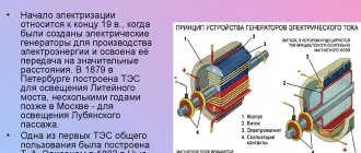
At the dawn of electrification, the DC generator remained the only source of electrical energy. Quite quickly, these alternators were supplanted by more advanced and reliable three-phase alternating current generators. In some industries, direct current continued to be in demand, so devices for its generation were improved and developed.
Even in our time, when powerful rectifier devices have been invented, the relevance of direct current generators has not been lost. For example, they are used to power power lines in urban electric transport used by trams and trolleybuses. Such generators are still used in telecommunications technology as sources of direct current in low-voltage circuits.
Design and principle of operation
The operation of the generator is based on the principle arising from the law of electromagnetic induction. If a closed circuit is placed between the poles of a permanent magnet, then when rotating it will cross the magnetic flux (see Fig. 1). According to the law of electromagnetic induction, at the moment of intersection, an emf is induced. The electromotive force increases as the conductor approaches the pole of the magnet. If a load R is connected to the collector (two yellow half rings in the figure), then current will flow through the formed electrical circuit.
Rice. 1. Operating principle of a DC generator
As the turns of the frame leave the zone of action of the magnetic flux, the EMF weakens and acquires a zero value at the moment when the frame is positioned horizontally. Continuing the rotation of the circuit, its opposite sides change magnetic polarity: the part of the frame that was under the north pole takes a position above the south magnetic pole.
The EMF values in each active winding of the circuit are determined by the formula: e1 = Blvsinwt; e2 = -Blvsinwt; , where B is magnetic induction, l is the length of the side of the frame, v is the linear speed of rotation of the circuit, t is time, wt is the angle at which the frame intersects the magnetic flux.
When the poles change, the direction of the current changes. But due to the fact that the collector rotates synchronously with the frame, the current at the load is always directed in one direction. That is, the model under consideration ensures the generation of constant electricity. The resulting EMF has the form: e = 2Blvsinwt, which means that its change obeys a sinusoidal law.
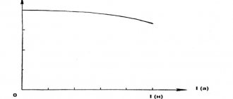
Strictly speaking, this design only ensures the polarity of the stationary brushes, but does not eliminate EMF pulsation. Therefore, the graph of the generated current looks as shown in Fig. 2.
Figure 2. Graph of the current produced by a primitive generator
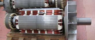
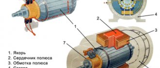
Such a current, except in rare cases, is not suitable for use. It is necessary to smooth out the pulsations to an acceptable level. To do this, the number of poles of permanent magnets is increased, and instead of a simple frame, a more complex structure is used - an armature, with a large number of windings and a corresponding number of collector plates (see Fig. 3). In addition, the windings are connected in different ways, which will be discussed below.
Rice. 3. Generator rotor
The anchor is made of sheet steel. The armature cores have grooves into which several turns of wire are placed, forming the working winding of the rotor. The conductors in the grooves are connected in series and form coils (sections), which in turn create a closed circuit through the collector plates.
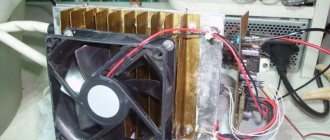
From the point of view of the physics of the generation process, it does not matter which parts rotate - the circuit windings or the magnet itself. Therefore, in practice, armatures for low-power generators are made of permanent magnets, and the resulting alternating current is rectified by diode bridges and other circuits.
And finally: if a constant voltage is applied to the collector, then the DC generators can operate as synchronous motors.
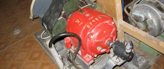
The design of the motor (aka generator) is clear from Figure 4. The stationary stator consists of two pole cores consisting of ferrimagnetic plates and field windings connected in series. The brushes are located in one line opposite each other. A fan is used to cool the windings.
Rice. 4. DC motor
Self-excited generator circuits
The most widely used are the so-called three-point generator circuits with self-excitation
, in which the lamp is connected to the circuit at three points: anode, cathode and control grid.
| In Fig. 167 shows a generalized three-point generator circuit without auxiliary elements; Resistances Zaс, Zск and Zаk should be understood as any combination of reactive and active resistances. They form the oscillatory circuit of the generator. Rice. 167. Generalized three-point scheme. |
In order for the system to be self-oscillating, the following conditions must be met:
- Resistances Zaс and Zсk must have opposite signs (if one of them has an inductive nature of resistance, then the second must be capacitive). Only if this condition is met will a phase shift close to 180° be ensured between the alternating voltages on the anode and on the grid.
- In absolute value, resistance |Zac| there should be more resistance |Zsk|. However, too small a value of Zск will not ensure that sufficient feedback voltage U'с is supplied to the grid of the generator lamp, which is necessary for stable operation of the generator.
- If the first two conditions are met, it is necessary that Zac have the same sign with Zsk, since with the help of resistance Zac the oscillatory system is tuned to the frequency of the generated oscillations.
The feedback coefficient in the general case can be defined as the ratio of the voltage between the grid and the cathode (Umc) to the voltage between the anode and the cathode (Umk):
(294)
The active components can be neglected, and then
Since the load is a parallel connection Zak and Zsk + Zac, then the equivalent circuit resistance
If we take into account that the active components of these resistances are much smaller than the reactive ones, and Hak = - (Xsk + Xac), then it is easy to show that
where r = rак + rск + rас is the total active resistance of the oscillatory system. Consequently, the load of the generator is the equivalent resistance of the circuit, consisting of Xac, Xac and Xsk; when tuning the circuit to resonance
Hack + Has + Xsk = 0
If X represents capacitance, then the generalized inductive three-point generator circuit with self-excitation
will have the form shown in Fig. 168, a.
| By properly connecting it to the lamp and power supplies and providing the necessary bias on the control grid, we obtain a self-oscillator circuit with autotransformer feedback. Rice. 168. Three-point circuits of tube generators: a - inductive; b - capacitive; c - double-contour. |
The vector diagram illustrates the fulfillment of the phase balance condition in the circuit under consideration. An alternating voltage at the anode creates a current LCL1 in circuit CL1, which leads the anode voltage Ua by 90°, since Xc > XL1. This current on the inductor coil forms a feedback voltage Uc, the vector of which leads the current vector ICL1 by 90°. The voltage Ua and Uc turned out to be out of phase by 180°, which corresponds to the normal operation of the circuit. The feedback coefficient is adjusted by moving the probe along the inductance turns of the circuit.
In Fig. 168, b shows a capacitive three-point generator circuit with self-excitation
, built on the same principle as the previous autotransformer. For her, the feedback coefficient
Double-circuit circuits of tube generators also find practical application. In these circuits, the role of resistance Zac is played by the interelectrode capacitance Cac. Self-excitation of the circuit occurs at a frequency higher than the resonant frequencies of circuits L1C1 and L2C2, since in order to fulfill the phase balance condition, these circuits must represent an inductive load (Fig. 168, c).
Classification
There are two types of DC generators:
- with independent excitation of windings;
- with self-excitation.
To self-excite generators, they use electricity generated by the device itself. Based on the principle of connecting the armature windings, self-excited alternators are divided into types:
- devices with parallel excitation;
- alternators with series excitation;
- mixed type devices (composite generators).
Let us consider in more detail the features of each type of connection of armature windings.
With parallel excitation
To ensure normal operation of electrical appliances, a stable voltage is required at the generator terminals, independent of changes in the total load. The problem is solved by adjusting the excitation parameters. In alternators with parallel excitation, the coil leads are connected through a control rheostat in parallel to the armature winding.
Excitation rheostats can short-circuit the winding to themselves. If this is not done, then when the excitation circuit breaks, the self-induction EMF in the winding will sharply increase, which can break through the insulation. In a short circuit condition, energy is dissipated as heat, preventing destruction of the generator.
Electric machines with parallel excitation do not require an external power source. Due to the presence of residual magnetism, which is always present in the core of the electromagnet, self-excitation of parallel windings occurs. To increase residual magnetism in field coils, electromagnet cores are made of cast steel.
The self-excitation process continues until the current reaches its maximum value and the EMF reaches its nominal values at optimal rotation speed of the armature.
Advantage: generators with parallel excitation are weakly affected by short-circuit currents.
With independent excitation
Batteries or other external devices are often used as a power source for field windings. Models of low-power machines use permanent magnets, which ensure the presence of the main magnetic flux.
On the shaft of powerful generators there is an exciter generator that produces direct current to excite the main armature windings. For excitation, 1–3% of the rated armature current is sufficient and does not depend on it. The EMF is changed by a control rheostat.
The advantage of independent excitation is that the excitation current is not affected in any way by the terminal voltage. And this ensures good external characteristics of the alternator.
With sequential excitation
The series windings produce a current equal to the generator current. Since the load is zero at idle, the excitation is zero. This means that the idle speed characteristic cannot be removed, that is, there are no adjustment characteristics.
In generators with series excitation there is practically no current when the rotor rotates at idle speed. To start the excitation process, it is necessary to connect an external load to the generator terminals. This pronounced dependence of voltage on load is a disadvantage of series windings. Such devices can only be used to power electrical appliances with a constant load.
With mixed excitement
Useful characteristics combine the designs of generators with mixed excitation. Their features: the devices have two coils - the main one, connected in parallel to the armature windings, and the auxiliary one, which is connected in series. A rheostat is included in the parallel winding circuit, which is used to regulate the excitation current.
The process of self-excitation of an alternator with mixed excitation is similar to that of a generator with parallel windings (due to the absence of an initial current, the series winding does not participate in self-excitation). The no-load characteristic is the same as that of an alternator with parallel winding. This allows you to regulate the voltage at the generator terminals.
Mixed excitation smoothes out voltage ripple at rated load. This is the main advantage of such alternators over other types of generators. The disadvantage is the complexity of the design, which leads to an increase in the cost of these devices. Such generators do not tolerate short circuits.
Methods for exciting synchronous generators
The most common way to create the main magnetic flux of synchronous generators is electromagnetic excitation, which consists of placing an excitation winding at the rotor poles, when a direct current passes through it, an MMF appears, creating a magnetic field in the generator. Until recently, special independent excitation direct current generators, called exciters B
(Fig. 1.3, a).
The excitation winding ( OB
) receives power from another generator (parallel excitation), called a subexciter (
SA
).
The rotor of the synchronous generator, exciter and subexciter are located on a common shaft and rotate simultaneously. In this case, the current enters the excitation winding of the synchronous generator through slip rings and brushes. To regulate the excitation current, control rheostats are used, connected in the excitation circuits of the exciter r
1 and the subexciter
r
2 . In synchronous generators of medium and high power, the process of regulating the excitation current is automated.
In synchronous generators, a contactless electromagnetic excitation system has also been used, in which the synchronous generator does not have slip rings on the rotor. B is used as an exciter
(Fig. 1.3, b).
The three-phase exciter winding 2
, in which an alternating EMF is induced, is located on the rotor and rotates together with the excitation winding of the synchronous generator and their electrical connection is carried out through a rotating rectifier
3
directly, without slip rings and brushes.
DC power supply of excitation winding 1
of exciter B is carried out from the subexciter
PV
- a direct current generator. The absence of sliding contacts in the excitation circuit of a synchronous generator makes it possible to increase its operational reliability and increase efficiency.
Technical characteristics of the DC generator
The operation of the generator is characterized by dependencies between the main quantities, which are called its characteristics. The main characteristics include:
- dependencies between values when idling;
- characteristics of external parameters;
- adjusting values.
We partially disclosed some adjustment characteristics and idle speed dependencies in the “Classification” section. Let us dwell briefly on the external characteristics that correspond to the operation of the generator in nominal mode. The external characteristic is very important, since it shows the dependence of voltage on load, and is taken at a stable armature speed.
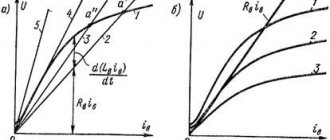
The external characteristic of a direct current generator with independent excitation is as follows: this is a curve of voltage versus load (see Fig. 5). As can be seen in the graph, a voltage drop is observed, but it does not greatly depend on the load current (while maintaining the speed of the engine rotating the armature).
Rice. 5. External characteristics of the GPT
In generators with parallel excitation, the dependence of voltage on load is more pronounced (see Fig. 6). This is due to a drop in the excitation current in the windings. The higher the load current, the faster the voltage at the generator terminals will drop. In particular, with a gradual drop in resistance to the short-circuit level, the voltage will drop to zero. But a sudden short circuit in the circuit causes a backlash from the generator and can be fatal for an electric machine of this type.
Rice. 6. Characteristics of GST with parallel excitation
An increase in load current with series excitation leads to an increase in EMF. (see top curve in Fig. 7). However, the voltage (lower curve) lags behind the emf because some of the energy is wasted in electrical losses from the eddy currents present.
Rice. 7. External characteristics of a generator with series excitation
Please note that when it reaches its maximum, the voltage begins to drop sharply with increasing load, although the EMF curve continues to tend upward. This behavior is a disadvantage that limits the use of this type of alternator.
In generators with mixed excitation, counter-connections of both coils are provided - serial and parallel. The resulting magnetizing force with consonant switching is equal to the vector sum of the magnetizing forces of these windings, and with counter switching - the difference of these forces.
During the process of smoothly increasing the load from idle to the nominal level, the voltage at the terminals will be almost constant (curve 2 in Fig. 8). An increase in voltage is observed if the number of conductors in the series winding exceeds the number of turns corresponding to the nominal armature excitation (curve 1).
The change in voltage for the case with a smaller number of turns in a series winding is depicted by curve 3. The counter-connection of windings is illustrated by curve 4.
Rice. 8. External characteristics of GST with mixed excitation
Generators with counter-connection are used when it is necessary to limit short-circuit currents, for example, when connecting welding machines.
In normally excited mixed-type devices, the excitation current is constant and almost independent of the load.
Anchor reaction
When an external load is connected to the generator, the currents in its winding form their own magnetic field. Magnetic resistance of the stator and rotor fields appears. The resulting field is stronger at those points where the armature approaches the poles of the magnet, and weaker where it runs away from them. In other words, the armature reacts to the magnetic saturation of the steel in the coil cores. The intensity of the armature reaction depends on the saturation in the magnetic circuits. The result of this reaction is the sparking of the brushes on the commutator plates.
The armature reaction can be reduced by using compensating additional magnetic poles or by shifting the brushes from the center line of the geometric neutral.
EMF
The average value of the electromotive force is proportional to the magnetic flux, the number of active conductors in the windings and the frequency of rotation of the armature. By increasing or decreasing these parameters, you can control the magnitude of the EMF, and therefore the voltage. The easiest way is to achieve the desired result by adjusting the armature rotation speed.
Power
A distinction is made between the total and useful power of the generator. At constant EMF, the total power is proportional to the current: P = EIa. The useful power supplied to the circuit is P1 = UI.
Efficiency
An important characteristic of an alternator is its efficiency - the ratio of useful power to total power. Let us denote this quantity by the symbol ηe. Then: ηe=P1/P.
At idle speed ηe = 0. The maximum efficiency value is at rated loads. The efficiency of powerful generators approaches 90%.
Application
Until recently, the use of DC traction generators in railway transport had no alternative. However, the process of replacing these generators with synchronous three-phase devices has already begun. The alternating current of the synchronous alternator is rectified using semiconductor rectifier units.
Some Russian locomotives of the new generation already use asynchronous motors operating on alternating current.
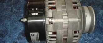
A similar situation is observed with car generators. DC alternators are replaced with asynchronous generators, followed by rectification.
Perhaps only mobile welding machines with autonomous power supply are invariably paired with DC alternators. Some industries have also not abandoned the use of powerful DC generators.