The main parameters of the TT are the following.
1. Rated voltage
- line voltage of the system in which the transformer must operate. This is the voltage for which the primary winding insulation is designed.
2. Rated primary and secondary current
- the current that the transformer can pass for a long time without overheating. The rated current of the secondary winding is standardized and can be 5 or 1 A. There can be several secondary windings with different rated currents.
3. Nominal transformation ratio
- ratio of rated primary current to rated secondary current:
4. Transformer rated load
- this is the load resistance
Z
2nom. in ohms, at which the transformer operates with a given accuracy class at the rated value Cos2nom. = 0.8.
Sometimes this term is replaced by the rated power in volt-amperes P
2nom.
R
2nom.
= 2nom Z
2nom
Since the current value I
2nom.
is standardized, then Z
2nom. determines
P
2nom. CT
5. Accuracy class.
Due to losses in the transformer, the actual transformation ratio is not equal to the nominal one.
There are current and angular errors. The current error in percentage is determined by the expression 100.
Depending on the value of the current error, accuracy classes are distinguished (0.5; 1). The accuracy class indicates the current error under rated conditions.
In an ideal transformer, the secondary current is phase shifted relative to the primary by 180°. In a real transformer, this angle differs from 180°. The angle error is measured in minutes.
6. Nominal limiting factor.
With an increase in the primary current above the rated value, the CT error first decreases, then increases as the magnetic circuit becomes saturated. TT is one of the main links in protection systems. With short circuit currents, the error may be such that normal operation of the protection will not be ensured. Therefore, for a CT, the maximum multiple of the primary winding current in relation to the rated current is indicated, at which the total error does not exceed 5 or 10% (different classes), and within this error the normal operation of the protection is designed.
7. Maximum secondary current ratio
– the ratio of the highest secondary current to its rated value at rated secondary
load. Maximum multiplicity I
2 is determined by saturation of the magnetic circuit, when a further increase
in I
1 does not lead to an increase in flux.
8. Thermal resistance -
the ratio of the maximum permissible short-circuit current, which the transformer can withstand without damage for a rated time of 1s, to the rated primary current
I
1nom at a rated secondary load and a normalized ambient temperature, taking into account preheating of the CT with a rated current.
9. Dynamic durability
CT (multiplicity) - the ratio of the amplitude value of the maximum through short-circuit current (short-circuit shock current), withstood by the transformer without mechanical damage, to the amplitude value of the rated primary current
I
1nom.
Since the current of the primary winding of the CT is set by the network, the primary winding is subject to the greatest thermal and dynamic influences. The secondary current is often limited by the saturation of the magnetic circuit, and therefore the secondary winding operates under lighter conditions.
Definition
The definition of technical characteristics for a transformer is prescribed in GOST 7746 2001 under the title “Current transformers. General technical conditions". This document belongs to the interstate class, that is, it applies to all devices manufactured anywhere in the country.
In order to understand the definition, you need to get acquainted with what the average safety factor means. This indicator in turn is the ratio of the rated safety current and the primary (also the rated total value). The safety factor is inherently the main parameter that determines the required pulse increase factor.
The last characteristic is important, since in production conditions situations are often observed when it increases from the nominal value. This occurs when there is a short circuit in the circuit in most cases.
The situation is determined by the fact that the TS core goes into saturation, while no growth is observed in the secondary, which in turn ensures protection of all connected loads to the equipment.
Measuring and calculating the limiting factor
When the maximum normalized indicator is exceeded, the device moves from the stable operating area to the saturation phase. The accuracy of the functional is assessed using mathematical curves, the conditions of which are given in the tables. The coefficient is not established empirically, but according to special tabular data. The curves consist of information about the largest ratio of secondary current to the average rated current supplied to the primary.
The calculation is made in such a way that the total error in the calculated data (that is, when including the specified information about the secondary load) does not exceed ten percent. Mathematical curves allow you to calculate the characteristics of wires, devices, relays, connection diagrams and create a circuit in such a way that oversaturation does not occur and the devices operate in optimal mode.
Equipment supplemented with differential protection must have an identical maximum multiplicity for through short-circuit current.
Design curves are given for calculations of work according to the established mode. If the aperiodic tends to max, that is, the mode is transitional, then the parameter reaches 70-75%.
The accuracy class is chosen depending on the purpose. The same requirements apply to devices with non-identical load types.
Checking the current transformer accuracy class
When powering the windings of meters for calculations with the power system, the error should not exceed 0.5%, measuring instruments - 1%, relay protection - 3%. Class 10P current transformers are used to connect differential protection and ground fault protection devices.
Below is a table of permissible secondary load values for some current transformers, depending on the required accuracy class:
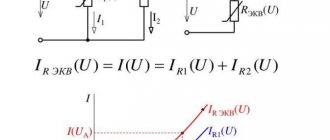
The secondary load of the current transformer Zn.t.t is the total resistance of the secondary circuit Z2 in ohms. It is equal to the sum of the resistances of all series-connected coils of devices and relays, transition contacts and connecting wires:
Where ∑Zapr. – the sum of the total resistances of the devices, Ohm; Zprov – resistance of connecting wires, Ohm; nk – number of contacts; 0.01 – average resistance of one contact, Ohm;
In the above formula, algebraic addition of impedances is allowed, which for this case does not give a serious error.
For practical calculations, the total contact resistance can be taken equal to 0.1 Ohm.
Taking the permissible Zn.t.t and the resistance of the switched-on devices from the catalogues, you can determine the required cross-section of the connecting wires:
As a rule, Zwire ≈ Rwire, therefore:
Where: lcalc. – estimated length in meters in accordance with the device connection diagrams (diagrams below); l is the actual distance of the connecting wires at one end from the terminals of the current transformer to the installation location of the devices.
The table below shows the average resistance data of measuring instruments and relays, which can be used to determine the load of the secondary circuit of the current transformer:
According to the conditions of mechanical strength, the cross-section of the wires of current-carrying circuits must be at least 2.5 mm2.
Example
Determine the cross-section of the copper connecting wires of the secondary circuit of the current transformer installed at the 10 kV input to the substation switchgear according to the diagram shown below. Current transformers must have an accuracy class of 0.5. The distance between the current transformers installed in the 10 kV switchgear and the switchboard in which the devices are installed is 20 meters. The resistance of the transition contacts is taken to be 0.1 Ohm.
Solution
Resistance of devices connected to the most loaded phase (in this case, phase A or C):
According to the catalog for the TPL10 current transformer with an accuracy class of 0.5 Zn.t.t = 0.4 Ohm.
We get the wire resistance values:
The cross-section of the wires is determined without taking into account the slight load of phase B. Then lcalc. = 1.5l:
The nearest standard value of 4 mm2 is accepted.
CT error limits for classes P
All characteristics are indicated in the documentation for specific types of devices. Also, information is registered separately for each device. Specifically for accuracy classes P, limits of permissible current and angular errors are established.
For transformers with power class 5P at a normal current with a maximum full multiple of 5 percent, the permissible error limits are as follows:
- current – + or – 1%;
- angular + or - 60 percent, which is identical to 1.9.
The limits indicated in the tables are met, since this is the first of the safety requirements.
For a device of accuracy class 10P, the required maximum factor is 10%, respectively. The maximum possible error limit during operation is 3 percent. At the same time, data on angular errors is not presented, since they are not standardized.
Checking the voltage transformer accuracy class
The voltage coils of measuring instruments and relays are connected to the secondary winding of the measuring voltage transformer.
The calibration of these devices is carried out in relation to the transformation ratio, based on the fact that the rated secondary voltage in all cases is 100 V.
The voltage transformer has an error that depends on the magnitude of the no-load current, as well as the resistance of the secondary load windings. The secondary load, as for current transformers, is indicated in factory catalogs, but not in ohms, but in volt-amperes (VA). For example, for a single-phase voltage transformer NOM-6, this load should not be more than 50 VA with an accuracy class of 0.5; with accuracy class 1 no more than 80 VA; with accuracy class 3 no more than 200 VA.
The magnitude of the connected load depends on the device connection circuit and can be determined for the most commonly used circuits using the formulas shown in the table below:
The full load is defined as the geometric sum of active and reactive powers consumed by the coils of connected devices:
The table below shows the approximate powers and power factors of the voltage coils of various devices:
The power losses in the secondary circuit wires of voltage transformers are so insignificant that they are neglected.
Example
Select the voltage transformer to which the measuring instruments are connected (according to the diagram below), if it must operate at an accuracy class of 0.5 and a network voltage of 6 kV.
Let's compile tables of load distribution between phases:
We choose a three-phase transformer NTMK-6-48, which allows a load of 80 VA with an accuracy class of 0.5.
Categories
Limit factor - the ratio of the limiting value of the primary current, at which the total error at a given secondary load does not exceed 10%, to the rated primary current
Nominal maximum expansion ratio, Knom – maximum expansion ratio at rated secondary load.
The maximum multiplicity of the secondary winding for protection determines the possibility of normal operation of protective devices and systems during emergency operating conditions.
Error curves of the secondary winding of a CT with an accuracy class of 10P and a rated secondary load of 15 VA, taken at various values of the secondary load
Maximum factor measurement
The value of the actual (measured) value of the limiting factor at a nominal secondary load, according to GOST 7746-2015, must exceed the value of the nominal limiting factor, and in reality it is always slightly higher.
The measurement of the maximum multiplicity is carried out during qualification tests by the direct method in accordance with GOST 7746-2015 clause 9.6. or indirectly with PSI by measuring the value of the magnetizing current. The magnetizing current, determined at the calculated value of the magnetizing voltage Unam.calc, must be less than the calculated magnetizing current for the CT protective windings.
where Knom is the nominal maximum factor of the windings for protection; ε – total error, for protective windings is taken equal to 5% for accuracy class 5P or 10% for accuracy class 10P; Z2 is the total resistance of the secondary winding, determined by the formula
The actual (measured at PSI) values of the magnetizing current, calculated voltage and calculated magnetizing current of the secondary windings are indicated in the passport for a specific transformer.
Ultimate factor curves
The maximum multiplicity directly depends on the actual value of the secondary load. For the correct design of protection systems, there are limiting factor curves , i.e. dependence of the maximum multiplicity factor on the loads on the secondary winding.
Dependence of the limiting factor on the loads on the secondary winding for the secondary winding of a CT with an accuracy class of 10P and a rated secondary load of 15 VA
Typical curves of the maximum multiplicity for current transformers produced by NTZ Volkhov LLC can be viewed at the link:
Maximum factor curves for non-standard transformers and complete I-V characteristics of secondary windings in tabular or graphical form, indicating control points, are available upon request.
Determination of the minimum required limiting factor Kpk.min
Depending on the type of protection, the current circuits of which are connected to the current transformer being tested, the value of Kpk.min is determined differently.
Also, depending on the type (class) of current transformers used, Kpk.min is determined differently. Below are formulas for determining Kpk.min for current transformers of class 5P, 10P.
Overcurrent protection
where: Israb.to – operation current of the highest current stage (as a rule, current cut-off); Iprim.tt – rated primary current of the CT.
Note: microprocessor devices may have their own requirements for Kpk.min. Thus, for Siemens devices of type 7SJ80, 7SJ81, 7SJ82 the minimum required limiting factor must be
Tire differential protection
For busbar differential protection devices type 7SS85
where: Is.max – maximum short-circuit current at the place where the protection is installed.
Transformer differential protection
For transformer differential protection devices of type 7UT82, 7UT85, the minimum required limiting factor is determined by three conditions
where: Iinternal short-circuit – maximum short-circuit current in case of damage inside the protected area; Iext.short circuit – maximum short-circuit current in case of fault outside the protected area (referred to the HV side).
Line differential protection
For function 87L of differential protection of a line of devices of type 7SD82, the minimum required limiting factor is determined by the formulas:
where: Iinternal short-circuit – maximum short-circuit current in case of fault on the protected line; Iext.short circuit – maximum short-circuit current in case of fault outside the protected line.
Measurement limit test
When checking current circuits, for any protection the following condition must be met:
where: ISC.max – maximum short-circuit current at the installation site of current transformers.