Operating principle of zero-sequence current directional protection in 110 kV electrical networks
In electrical engineering there is a concept of symmetrical and asymmetrical systems of phase currents or voltages.
A symmetrical system provides for equality of phase currents (voltages) of a three-phase network. In this case, the phase current vectors can be relative to each other in direct, reverse, and zero sequence (NP). With direct sequence, the phase current vectors go in the sequence A, B, C, each phase lags behind the other by 120 degrees. Reverse sequence - alternation of phases A, C, B, phase shift angle is the same - 120 degrees. With zero sequence, the vectors of the three phases coincide in direction. An asymmetrical system is represented as a current value - the geometric sum of the vectors of all components of the positive, negative and zero sequence.
In the normal operating mode of an electrical network section, the system of currents and voltages is symmetrical, the same applies to interphase short circuits. In this case, both the voltage and current of the NP are zero. In the event of a single-phase ground fault, the system becomes asymmetrical - current and voltage arise.
In this case, the current (voltage) of one of the zero-sequence phases is equal to a third of the sum of the vectors of the asymmetric system, respectively, the sum of the vectors of the asymmetric system is the triple current (voltage) of the NP.
The results of calculations of short circuits in electrical networks also show that the current of a single-phase ground fault in electrical networks is equal to the triple value of the NP current - 3I0, and the voltage arising between the neutral of the transformer and the short circuit point is equal to the triple value of the NP voltage - 3U0.
The principle of operation of zero-sequence current protection is to control the value of 3I0 on the power line and, if it reaches a certain value, to implement automatic shutdown of the power line switch with a certain time delay.
In practice, unbalance currents 3I0 are obtained at the output of the so-called zero-sequence current filter. This filter is obtained by electrically connecting the beginnings and ends of the windings of the current transformers of each of the line phases.
In the normal operating mode of a section of the electrical network, there is no current at the output of the NP current filter. If damage occurs - one of the phase wires of the power line falls to the ground, an imbalance occurs - a certain current value 3I0 appears, the value of which is fixed at the output of the NP current filter.
TNZNP, as a rule, is multi-stage protection. Each of the protection stages has its own response time delay. To ensure selectivity of protection operation at adjacent substations, sections of the electrical network are divided into sections (action zones). Thus, the protection provides protection for the power line supplied from the substation where this set of protections is installed, and acts as backup protection for adjacent substations.
There is such a thing as swings in the system. If protection against phase-to-phase short circuits, for example, distance protection, can falsely trigger when this phenomenon occurs, then false triggering of TNZNP is excluded, since this protection reacts exclusively to the occurrence of zero-sequence currents, the occurrence of which is not typical for the phenomenon of swings in the power system.
Protection of distribution network transformers - differential current protection
The protection discussed in the article is, in fact, protection against earth faults, therefore this protection has an alternative name - earth protection (EP).
What devices perform the function of directional zero-sequence current protection in electrical networks
To ensure protection of power lines from all types of damage (both single-phase and interphase short circuits), zero-sequence current protection is implemented together with distance protection. Devices that perform the functions of these protections can be made both on relays of the electromechanical operating principle, and on modern devices - microprocessor protection terminals.
Among electromechanical protections, the most popular are the EPZ-1636 type kits, which have several different modifications. In modern conditions, when constructing new distribution substations or technical re-equipment of old facilities, preference is given to microprocessor-based protective devices. To implement backup protection of 110 kV lines, including TNZNP, microprocessor terminals manufactured by ABB, for example, the REL650 multifunctional device, are often used.
What is zero sequence current protection
The most common fault in a three-phase network is a ground fault. Interphase faults are less common. In 110 kV networks, zero sequence current protection, abbreviated TZNP, is used against single-phase ground faults. In this article we will look at its design, principle of operation and purpose.
What is a zero sequence
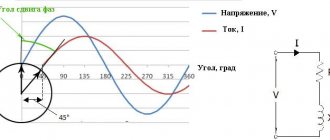
In order to understand how TZNP works, you first need to remember what a three-phase network is. A three-phase network is an alternating sinusoidal current network. In a three-phase circuit, the phases are shifted relative to each other by 120 degrees. This is what it looks like on the graph:
Interesting! The basic ideas and provisions of three-phase power supply networks were developed by Mikhail Osipovich Dolivo-Dobrovolsky. He developed a three-phase asynchronous motor with a short-circuit rotor of the squirrel cage type, with a wound rotor and a starting rheostat, a spark arrester grid, a phase meter, and a dial frequency meter.
If you depict this on a vector diagram, the image will resemble a three-pointed star. Provided that the currents and voltages between the phases are equal, such a system will be called symmetrical. The geometric sum of these vectors is zero.
Important! There are direct and reverse phase sequences. The phases are designated by the letters A, B and C. Then the sequence ABC is forward, CBA is reverse. In this case, the phase shift angle in both cases is 120 degrees. With a zero sequence, the vectors of all phases are directed in the same direction; accordingly, the resulting vector is significantly higher than that (3 times compared to the zero sequence) in the normal state of the system.
In the event of an interphase fault, the currents in all phases will increase, but the system will still remain symmetrical. And zero sequence voltages and currents are equal to zero, as in the normal state of the circuit.
As a result of a single-phase ground fault, the system will become asymmetrical and zero-sequence currents I0 and U0 will be observed. Suppose phase C is closed, then the currents of phases A and B will rush to zero, and in phase C to a third of Is.
Then:
I0=1/3(Ik+0+0)
Hence Ik=I0*3. These currents arise under the influence of short-circuit voltage or Uk0 between the terminal of the transformer or generator winding and the point at which the short circuit occurred.
Scope of application in practice
The theoretical part is quite difficult to comprehend without prior preparation, so let’s move on to practice and answer the question of where TZNP is used.
As already mentioned, zero-sequence current protection is used in high-voltage networks with a voltage of 110 kV with a grounded neutral. In medium voltage networks of 6, 10 kV and more with an insulated neutral it is not used. This is due to the fact that in networks with a grounded neutral, short-circuit currents to ground are very large.
Important! Since TZNP protects against short circuits to ground, it is sometimes called ground protection (GP).
Selecting settings for TZNP
To ensure the stepwise principle of line output, the current protection that controls the appearance of a zero sequence in the circuits must correspond to the selectivity of operation. Here, selectivity refers to the sequential switching off of certain sections of the circuit, depending on their significance, in order to determine the location of the damage or highlight the damaged gap. To do this, select the appropriate time settings for protection. Consider an example of setting settings in this diagram.
As you can see, in this case the TZNP is configured according to the same principle as the maximum current protection, but with a shorter time delay. In this example, each subsequent protection stage withstands a time delay for an interval Δt greater than the previous one. That is, the response time of the first current cutoff, in comparison with the second, will be calculated according to the formula: t1 = t2+ Δt. And the response time of the second in relation to the third will be t2 = t3+ Δt. Thus, each subsequent relay performs the function of backup protection.
This system of stepwise protection allows minimizing the further transfer of damage to other sections of the network and power equipment. It also helps to remove the personnel servicing these devices from danger. The main requirement for current protection is the prevention of false switching in relation to the corresponding trigger zone.
Terminal "TOR 300 RZT 52X"
| Current circuits | IA,HV, IB,HV, IC,HV – phase currents of the HV side 3I0,HV – zero sequence current of the HV side |
| Voltage circuits | UAB,CH, UBC,CH – linear voltages of the CH side UAB,NN1, UBC,NN1 – linear voltages of the NN1 side UAB,NN2, UBC,NN2 – linear voltages of the NN2 side |
| DC and voltage circuits | IEMO1, IEMO2, IEMV – direct currents of electromagnets UEM1, UEM2 – constant voltages of electromagnets |
| Digital inputs | 53 pcs. |
| Output relays | 53 pcs. |
The terminal provides oscillography with a sampling frequency of up to 2000 Hz and storage of up to 200 records in non-volatile memory.
Relay protection and automation of power supply systems
Gas protection
Action is provided from the signal and shutdown stages of the gas protection of the transformer tank and the gas protection (jet relay) of the on-load tap-changer tank. Monitoring of the insulation of gas protection circuits using RKTU with an effect on the alarm system has been implemented, and it is possible to block the action to disconnect from a faulty gas protection. A minimum duration of disconnection from gas protection is ensured to eliminate the influence of contact bounce.
The shutdown stage of the gas protection can be switched to a signal using an operating switch, the signal stage can be switched to shutdown using a software overlay.
HV LEVEL
The failure backup device for the HV circuit breaker is made with current control using a current relay with a short return time (no more than 20 ms). If the circuit breaker fails, the HV Voltage Level switch acts to disconnect adjacent circuit breakers through the DZSh circuits. It is possible to perform a breaker failure failure with an automatic action on your circuit breaker (action “on yourself”) to check its serviceability, or with control of the action on the shutdown electromagnet upon the loss of the RPV signal from the automatic control of the circuit breaker.
TZNP VN
The zero-sequence current protection of the HV side is non-directional and acts on disconnection through four time delays: to disconnect an adjacent transformer with an ungrounded neutral, to divide SHSV/SV, to disconnect its own HV circuit breaker and the transformer from all sides. A stage is provided for disconnecting the HV switch when the transformer is operating with an ungrounded neutral; this stage is entered automatically upon the absence of zero-sequence current in the neutral of “its” transformer and its presence in the neutral of the adjacent transformer, as well as the start-up of the HV negative sequence current relay.
MTZ VN
The maximum current protection of the HV side is made with voltage triggering of the MV, LV1 and LV2 sides and acts to disconnect the transformer from all sides. Provision is made for switching on the MTZ HV current relay for the difference in phase currents. MTZ VN has up to three stages, one of which can be used as a current cut-off.
Primary and backup protection: myths and reality
Automatic circuit breaker control
- three-phase automatic re-closing of connections and buses with control and synchronism capture;
- turning on the switch from the control key and according to the AR logic;
- disconnecting the switch from the control key and from protection (via EMO 1 and EMO 2);
- pickup of switch tripping when current flows into the EMO;
- pickup of switch on when current flows in the EMW.
Circuit breaker protection
Design and principle of operation of networks with solidly grounded neutral
The operating principle of electricity sources, in particular step-down transformers, is based on the law of mutual induction and energy transfer through a magnetic core. In this case, the primary winding may not have a neutral wire, in contrast to the secondary, where connecting it to zero through a conductor with low resistance, which can be equated with a zero value, will be an effective means of protecting a person from being hit by a voltage dangerous to his life and health.
The main feature of networks with a solidly grounded neutral is the appearance of not only linear, but also phase voltage. Let's look at what it is and how it differs from each other using a simple circuit diagram as an example.
Phase voltage is the potential between one of the line wires and the zero point connected to the ground, that is, tightly grounded. Line voltage is the potential difference between the two terminals of the lines, that is, L1 and L2, L1-L3, or L2-L3, it is also called phase-to-phase. Such sources of electrical energy in domestic conditions have a common voltage value in the form of 380 V - linear, and 220 - phase. Line voltage is greater than phase voltage by √3, that is, by 1.72.
But the main task of such a system is not only to transport voltages of two values to consumers with different numbers of phases in one power supply system, but also to protect people in the event of insulation breakdown and the appearance of voltage at points that normally do not have a dangerous potential. In residential buildings this is:
- the housings of all household appliances that conduct electric current, that is, made of steel or other conductive metal;
- metal structures of switchboard and distribution devices;
- protective sheath of cables.
Also, to ensure safety, all of the above elements must be grounded; in this case, the danger from the use of voltage and the use of household appliances in networks with a solidly grounded neutral will be minimal. Moreover, for such circuits, uniform distribution of single-phase loads is required.
Concepts about positive, negative and zero sequence systems
Rice. 13.3
A direct sequence system consists of three vectors of equal length and shifted relative to each other by. Moreover, it lags behind the vector (Fig. 13.3 a).
In a negative sequence system, the vector leads
(Fig. 13.3 b).
The zero sequence system consists of three equal vectors
(Fig. 13.3 c).
Any asymmetrical system of three-phase voltages, currents, EMF can be represented as the result of the superposition of direct, negative and zero sequence systems (Fig. 13.4).
(1)
Or
(2)
The reverse action is also true - if the symmetrical components of the forward, negative and zero sequences are somehow found, then using formulas (1) or (2) you can determine the initial asymmetrical voltages and currents in a three-phase circuit (by the superposition method).
(3)
The initial task (action of the method) is to search for symmetrical components and similar asymmetrical (emergency) modes. It is carried out by calculating three symmetrical modes: direct, reverse and zero.
Each symmetrical mode is calculated according to its own equivalent circuit, and the direct and reverse sequence circuits are similar (have the same configuration).
The circuit is drawn up arbitrarily using the compensation principle, according to which any resistance Z of the electrical circuit can be represented as equivalent to sources of EMF directed towards the current in the original branch (Fig. 13.5).
In equivalent circuits, the phase resistances of the transmission line of three-phase transformers and three-phase electrical machines have different values for direct, negative and zero sequence currents.
Transmission lines
In transformers, zero-sequence magnetic fluxes are in phase and therefore cannot be closed through the core and therefore are closed through the air (Fig. 13.6).
The magnetic fluxes of the direct () and also reverse () sequences are shifted the most and therefore are closed along the core.
Rice. 13.6
Since the magnetic resistance of air is much greater than the magnetic resistance of steel, then.
It leads to .
In electric machines, the positive sequence of stator currents creates a magnetic field that rotates in the same direction as the rotor, and the reverse system of currents creates a magnetic field in the opposite direction. Consequently, the frequencies of currents induced in the rotor (direct and reverse) turn out to be different. This conducts to (the phase resistance of an electrical machine for positive sequence currents is not equal to the negative sequence).
Zero sequence stator currents do not create a circular rotating magnetic field; the conditions for their flow in the machine differ from the conditions for positive and negative sequence currents. As a result.
To move from the original circuit to equivalent circuits, proceed as follows: The place where the emergency mode occurs is characterized by asymmetrical voltages, which, based on the compensation principle, are represented by sources of fictitious, asymmetrical EMF (voltages)
Control questions
1. What do damage and accidents lead to in energy systems?
2. What two groups are asymmetry divided into?
3. What does the method of symmetrical components allow the problem to be reduced to?
4. What does a zero sequence system consist of?
5. Can any asymmetrical system of three-phase voltages, currents, EMF be represented as a result of the superposition of positive, negative and zero sequence systems?
6. If the symmetrical components of the positive, negative and zero sequences are somehow found, is it possible to determine the original asymmetrical voltages and currents in a three-phase circuit?
7. What is the original purpose of the overlay method?
8. What sequence of stator currents creates a magnetic field in electric machines?
CURRENT DIRECTIONAL ZERO-SEQUENCE PROTECTION
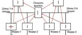
In networks with grounded neutral points located on both sides; sides of the considered section of the network, the selective action of the maximum current protection of the zero sequence can be ensured only if there is a power direction element (for reasons similar to § 7-1).
Directional zero-sequence protections operate during short circuits. on the protected line and do not work if there is damage on all other connections leaving this substation. This protection behavior is ensured using a power direction relay that responds to the sign or direction of the zero-sequence power during a short circuit.
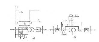
Time delays on protections operating in one direction of power are selected according to a stepwise principle. In Fig. Figure 8-7 shows the placement of directional zero-sequence protections and their time delay graph. The protection circuit is shown in Fig. 8-8.
The protection consists of a current relay 1,
reacting to the appearance of a short circuit.
to ground, power relay 2,
which determines the direction of power during a short circuit, and time relay
3,
which creates the time delay required by the selectivity condition.
The starting relay and the current winding of the power relay are connected to the neutral wire of the current transformers for a current of 3 I
0, and the polarizing winding (voltage winding) of the power relay is powered by a voltage of
3 U 0
from the open triangle of the voltage transformer.
When the relay is turned on this way 2
reacts to the power of the zero sequence So = UоIо.
Taking into account the internal shift angle α of the polarizing winding and the equalities Uр = З U 0 , I Р
== 3
I
0 the power direction relay according to (7-1) responds to power:
where φp = φ0 is the phase shift angle between U р
and /p or
U 0
and /0.
The operating conditions of the power relay and its behavior can be understood by examining the vector diagrams of the voltage and current of the supply relays ( U 0
and
I
0) for single-phase and two-phase short circuits. to the ground (Fig. 8-9 and 8-10).
Single-phase short circuit. [L. 32, 13], for example, in phase A
characterized by the following conditions arising from Fig.
8-9, a:
1) In damaged phase A
under the influence of e.
d.s. EA
passes short-circuit current.
1a
=
I
k. If we take the active resistance of the network equal to zero, then the current
1A
lags behind the e.
d.s. Ea
at 90°.
2) Currents in undamaged phases 1V
and /c are equal to zero.
3) Voltage of damaged phase A
relative to the ground at point
K U аK =
0, since this phase has a solid short circuit to the ground.
From diagram 8-9, b
it follows that the current
I ok
leads the voltage U
ok by
Vector diagram of a single-phase short circuit. at point P,
remote from the short circuit location, differs from the previous case in the value of
U a
The above diagrams were constructed with the above assumptions and are therefore approximate.
More strictly and accurately, similar diagrams can be constructed based on the joint solution of equations that characterize this type of damage, expressing the relationship of symmetrical components with phase currents and voltages. Diagrams constructed in a similar way for the short circuit location. shown in Fig. 8-9, g, d
and 8-10,
d, e;
the original equations are also given there (for more details about these diagrams, see [L.10, 13, 32]).
Vector diagrams in Fig. 8-9 and 8-10 allow us to draw the following conclusions:
1. The shift angle φр = φ 0, which determines the sign and magnitude of the power Sp to which the zero-sequence power relays react, is equal according to Fig. 8-9, beating 90°. When taking into account the active resistance of the network, φ0 is 100-120°.
It follows that for directional zero sequence protection it is necessary to use sinus or mixed type power relays,
having a maximum moment in the range of values φр = 90 ÷ 120°.
Similar relays include relays of the RBM-177 and RBM-178 types, in which Me =
kUpIp sin (α - φр) and angle α = - 20°.
The angle of maximum sensitivity of these relays, as follows from the above expression, is φmch = α - 90° = - 20° - 90° = - 110° or with the factory designation for unipolar current and voltage terminals φm.ch = 180-110 = + 70°. This value of φm.h is indicated in catalogs and reference books.
2. Current 3 I
0 for single-phase short circuit
is equal to I
k (in single-sided power supply mode), and with a two-phase short circuit. with the ground - the geometric sum of the currents of the damaged phases, i.e., the short-circuit current passing through the ground.
3. Voltage 3 U 0
has the greatest value (equal to the phase voltage) at the short circuit location.
(point K).
As you move away from the point of damage K
voltage
3 U 0
decreases.
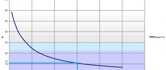
This follows from the diagrams in Fig. 8-9, b, c and 8-10, b, c,
as well as from equation (8-2c) and is shown graphically in Fig. 8-3.
From expression (8-2c) and Fig. 8-3, in
it follows that
the farther from the short circuit location.
the power relay is located, the worse its operating conditions. Indeed, the power Sp at the relay terminals decreases with decreasing
U 0 .
The dependence
U 0 = f (lp-k)
(Fig. 8-3,
c)
can be considered as the dependence S0 =
f (lp-k),
if we assume that Iр and φр are constant. With remote short circuits the power Sp may be less than Sc.р, as a result of which the power relay, and therefore the protection, will not work.
To expand the coverage area of zero sequence protection, highly sensitive power relays are required.
4. Vector diagrams, especially with a single-phase short circuit, clearly show that with a positive φк the angle φ0 is negative.
This means that the power S 0 and the power of the p.c. in the damaged phase S K have opposite signs.
For example, with a single-phase short circuit.
on the protected line (Fig. 8-9, a)
short-circuit power.
in phase has a positive sign and is directed from the power source to the short-circuit location, while the zero-sequence power is negative, i.e., directed from the short-
circuit location.
to the zero point of the transformers.
Therefore, the voltage and current windings of the zero-sequence power relay must be connected with opposite polarities.
Directional protection settings. The operating current of the starting current relay is selected in the same way as for non-directional zero-sequence protection (see § 8-2).
The sensitivity of the starting protection relay is checked during a short circuit. at the end of the second section according to formula (8-11).
On very long lines, you should additionally check the sensitivity of the power relay at k.i.
at the end of the protection zone according to the expression
kch
=
S rmin / S avg,
where Sr.min is the power at the relay terminals in the mode when
U 0
and
I
0 have a minimum value.
The time delays of directional protection are selected according to the counter-step principle (Fig. 8-7). Each protection is tuned from the neighboring protection, operating in one direction of power, by step Δ t
:
t
1=
t
3+ Δ
t .
Practical implementation of TZNP
Today, current protection that responds to the occurrence of a zero sequence can be implemented by microprocessor units and through relays. In most cases, outdated relays are widely replaced with newer versions of current protection. But, in addition to TZNP, remote, differential protection and other devices are configured for operation. Whose work is based on both symmetrical components and other network parameters.
In addition, in its classic design, TZNP does not have the ability to determine the location of damage. That is, it does not matter to her where the break occurred. Therefore, directional protection is used to determine the direction in which current flows towards ground. Such a system is built not only on currents, but also on voltage arising from the zero sequence. These values are supplied from voltage transformers connected in an open delta system.
When there is a short circuit in the current protection redundancy zone, voltage is supplied to one of the windings of the power relay, and a zero-sequence current used for current protection is supplied to the second winding. Provided that the power vector is directed into the line, the power relay unblocks the operation of the current protection. Otherwise, when the power direction indicates that the fault has occurred in another section, the power relay will continue to block the current protection from tripping.
Today, the practical implementation of such protection is carried out using REL650 microprocessor units or EPZ-1636 relays. Each of which already includes current cut-off, distance protection, and a starting relay to restore power.
What is a zero sequence?
The vast majority of networks are powered by a three-phase system. Which is characterized by the fact that the voltage of each phase is shifted by 120º.
Rice. 1. Voltage form in a three-phase network
As you can see from Figure 1, diagram b) shows the operation of a balanced symmetrical system. Moreover, if you perform a geometric addition of the presented vectors, then at the zero point the result of the addition will be equal to zero. This means that in 110, 10 and 6 kV systems, which are characterized by grounding of the transformer neutrals, under normal operating conditions there will be no current in the neutral. It should also be noted that geometrically, phase changes can be divided into the following types:
- direct sequence, in which their alternation looks like A – B – C;
- reverse sequence, in which the alternation will be C – B – A;
- and a zero sequence variant corresponding to the absence of a shift angle.
For the first two options, the shift angle will be 120º.
Rice. 2. Direct, reverse and zero sequence
Look at Figure 2, here the zero sequence, unlike the other two, shows that the vectors have the same direction, but their displacement in space between themselves is 0º. A similar situation occurs with a single-phase short circuit, while the currents of the two remaining phases rush to the zero point. This situation can also be observed during phase-to-phase faults, when two of them, in addition to overlap, also reach the ground, and only one phase current will flow at zero.
If a three-phase short circuit occurs in the neutral of the windings, the current will not flow, despite the accident. Because zero sequence currents and voltages will still be absent. Despite the fact that phase voltages and currents in this situation can increase significantly in comparison with the nominal ones.
Operating principle of TZNP
Almost all relay protections, the action of which is adjusted against the appearance of zero-sequence currents, have a similar principle. Consider the following diagram demonstrating the effect of protection.
Schematic diagram of the simplest TZNP
Here is an option for switching on a current relay T, which is connected to the secondary windings of current transformers (CTs) assembled in a star. In this situation, the neutral wire from the star of the transformer windings filters out the zero sequence components if they occur. Provided that the system operates symmetrically, the windings of relay T will be de-energized. And provided that a ground fault occurs in one of the phases, the CT will react to this, causing current to flow through the neutral wire. This will be the very component of the zero sequence, due to which the relay winding T will be excited.
After which a time delay occurs, determined by the parameters of relay B. When the set period of time expires, the current protection sends a signal to the corresponding switching installation U, which disconnects the three-phase network. More complex circuit options may also include a power relay, which allows you to debug the operation of the protection in direction.
In the case of phase-to-phase damage, the symmetry will not be broken, but only the magnitude of the currents will change. And the CTs will continue to compensate for the currents flowing into the neutral wire. The advantage of this scheme is that at maximum operating currents, the protection will still not operate, since symmetry will be maintained.
But if there is a significant difference in the magnetic parameters of the measuring transformers, an imbalance will occur in the system, and an unbalance current will flow through the neutral conductor. This can cause false trips of current protection even in those networks where the rated power supply is observed.