The word “comparator” comes from the Latin “comparare” and literally means “to compare” in Russian. It is produced in various modifications that are in demand in the modern electronics industry. The simplest designs for comparing monitored data have 2 analog inputs and one digital. The basis for its functioning is provided by a differential cascade with powerful amplification characteristics. A voltage comparator is a fairly popular device and is used in areas related to measurements or that use signal conversion from analog to digital.
What is a voltage comparator
The operating principle of a voltage comparator (VC) can be compared to a lever-type scale. When a reference weight is placed on one pan of the scale, and the product being measured is placed on the other. At a time when the weight of the product is the same as the mass of the reference weight, the bowl with the reference weight rises higher, after which the weighing process ends.
Application of comparators
In the CV, the main voltage functions instead of weights, and the product replaces the incoming signal. When a logical “1” is formed at the output of the comparator, the process of comparing voltage values begins. To check such a device, you do not need to perform a labor-intensive circuit. It is enough to connect the output voltmeter, and an adjustable voltage to the inputs. When changing the input parameters on the voltmeter, the CV functionality will be visible; the settings are set by the circuit.
Analog comparator circuit with hysteresis on an operational amplifier
The operating diagram of the circuit with hysteresis is similar, the only difference being that turning on and off does not occur at the same voltage.
When reading such a graph, you should pay attention to the direction of the arrows; they show the direction of movement of the hysteresis. Moving from left to right we see that the transition to low level occurs only at voltage Uph, and moving from right to left the output voltage will reach a high level only at voltage Upl.
This solution leads to the fact that at the moment when the voltages at the inputs are equal, there is no change in state at the output; for this it is necessary that the voltages differ by a significant amount.
True, such a solution causes a certain inertia of the system, but, of course, it is safer compared to a circuit without hysteresis. Often such operation can be observed in heating devices containing a thermostat (irons, stoves, etc.). Below is a circuit diagram of an operational amplifier that implements hysteresis:
And here is the dependence that allows you to calculate all the voltages:
Operating principle of the comparator
The simplest device is considered a comparator, which compares the voltage supplied to one of the inputs with the base indicator present at the other input. A primitive voltage comparator on an operational amplifier (op-amp) - without feedback.
Principle of operation
The CV is designed as an electronic circuit with 2 input voltages and can set a higher value. It is easy to perform CV models from an op-amp, since the polarity of the output circuit of the operational amplifier comes from the polarity of the difference in voltage values at the 2 inputs.
Let's imagine that there is a photocell that produces 0.5 V when exposed to sunlight, and it is necessary to use this photocell as a meter to set the period of daylight. In such cases, the best option is to use CV to match the voltage from the photocell to the controlled value of 0.5 V.
In the CV circuit, the initial reference voltage is supplied to the inverting input (U -), after which the voltage, which will be compared with the reference, is supplied to the non-inverting input. The output value is solely dependent on the input size with respect to the reference voltage.
You may be interested in Voltage measurements with a multimeter
Comparator circuit
Comparator circuit:
- Less than the reference - negative;
- equal to the reference one - “0”;
- more than the reference value - positive.
A comparator op-amp compares one analog voltage level with another analog voltage level or some reference voltage, and produces an output based on this voltage comparison. In other words, the op-amp voltage comparator compares the data of 2 inputs and determines the largest one; the simplicity and efficiency of this circuit has been tested in practice and is implemented in many household appliances.
Positive Feedback
Voltage comparators either use positive feedback or no feedback at all in open-loop mode. The VC output is then applied entirely to its positive supply rail +Ucc or to its negative supply rail -Ucc, upon application of an ac input signal that passes some preset threshold.
KN (-) feedback
Equivalent circuit of a voltage comparator with a bipolar power supply
The LM339, LM393 and LM311 voltage comparators can operate with single or dual power supplies up to 32 volts maximum.
When operating with a dual supply, the voltage comparison mode remains the same, except that for most circuits the emitter of the output transistor is connected to the negative supply rail rather than to the common circuit. An exception to this rule is the LM311 operational amplifier, which has an isolated emitter that can be connected either to the negative of a single-polar power supply or to the common wire of a bipolar one.
Read also: Which battery is better to take a screwdriver with?
When working with a bipolar power supply, the input voltage may be higher or lower relative to the common wire of the power supply. In addition, one of the comparator inputs can be connected to a common wire, thus creating a “zero crossing” detector.
Device parameters
In fact, the device can be regarded as a simple voltmeter. KN, like a digital device, has a number of operational qualities, divided into 2 types: static and dynamic.
Device parameters
The first ones have the following characteristics:
- Maximum sensitivity in relation to the threshold signal sizes that the SC sets at the input and replaces the device output potential with a logical “0” or “1”.
- The size of the displacement is set by the transfer factor of the device in relation to the established reference position.
- Input current is the maximum value that can flow using any output without causing damage to the device.
- Output current - the size of the current during the transition of the meter to position “1”.
- The current difference is the result determined by subtracting the current data.
- Hysteresis is a difference in input signal levels that causes a change in the stable output state.
- The signal reduction coefficient is calculated in relation to the differential signal, which leads to a change in the operating mode of the meter.
- The lowest and highest rated temperature is the interval in which the technological characteristics of the device will not change.
Comparator hysteresis
Please note! All main parameters of the CN are depicted in the form of transition type parameters. This is a chart where the X axis represents time and the Y axis represents voltage in volts.
Voltage Comparator - Open Collector Output
Typically, the output of a voltage comparator is an open collector output.
The open collector output has negative polarity. This means that there is no positive signal at this output and the load must be connected between this output and the power supply.
In some circuits, a load (pull-up) resistor is connected to the output of the comparator in order to provide a high level signal arriving at the input of the next circuit element.
Operational amplifiers (op amps) such as LM324, LM358 and LM741 are not commonly used in electronic circuits as voltage comparators due to their bipolar outputs. However, these op amps can be used as voltage comparators by connecting a diode or transistor to the op amp output to create an open collector output.
Below is the operating logic of a comparator with an open collector output:
2 in 1 soldering station with LCD display
Power: 800 W, temperature: 100...480 degrees, air flow...
More details
Current will flow through the open collector when the voltage at the (+) input is lower than the voltage at the (-) input. And accordingly, current will not flow through the open collector when the voltage at the input (+) is higher than the voltage at the input (-).
How is a comparator indicated in diagrams?
On comparator circuits and electrical circuits, the graphic designation of the meter is in the shape of a triangle with three outputs. They are indicated by the symbols “+” and “-”, corresponding to non-inverting/inverting indicators, and the output marking sign “Uout” is also presented.
You may be interested in this Metal detector for wiring
Designation on diagrams
When (+) at the input of the microchip, the signal strength becomes greater than that at the inverse (-), then a stable value will be formed at the output. Based on the circuitry of the comparator, this number can take the logical “0” or “1” variant. In digital electronic devices, “12” is a signal whose voltage level is 5V, and “0” is its absence. In other words, the meter output position is set to either high or low. Although usually in practice a potential difference of up to 2.7 V is taken as logical “0”.
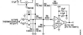
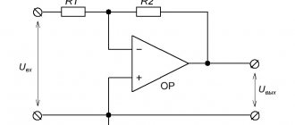
Operational amplifier analog comparator circuit
This circuit compares two voltages and, depending on their state, switches the output signal to a high or low state. We can say that this system combines analog and digital electronics.
It is quite interesting, since it has no feedback (in the basic version), this in turn suggests that the loop resistance is infinitely large.
We supply the processed signal to the positive input, and a fixed (reference) voltage set by a potentiometer to the negative input. Since there is no feedback loop, the gain is infinitely large.
Where is a voltage comparator used?
Often CN is used in a gradient relay - a circuit that responds to the rate of change of the signal, for example, a photo relay. Such a device can be used in situations where the lighting changes quite rapidly. For example, in security installations or sensors for monitoring released products on conveyors, where the device will respond to interruptions in the light flow.
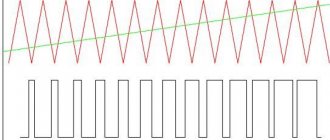
Another commonly used circuit is a sensor that measures temperature and changes the “analog” signal to an “electronic” one. Both meters convert the amplitude of the incoming signal into the width of the output pulse. This transformation is quite often used in a variety of digital circuits. Mainly in measuring devices, switching power supplies, electronic amplifiers.
Let's look at its work together.
Most understandably, the operation of this circuit is represented in the form of the operation of some constant comparing device, which constantly compares signal 1 and signal 2 supplied to the input of the comparator. It sets the output based on the following:
Is signal 1 higher in voltage than signal 2?
If yes, then the output is set to 10V (op-amp supply voltage). If not, then at 0V.
Fig.2. A visual description of the comparator's operation
At first glance, there is nothing unusual in the operation of this circuit, but there are countless applications for the operation of this circuit. Basically, these are devices that convert an analog signal into some logical value: YES or NO. This could be a battery charging indicator, a critical liquid level sensor in a vessel, or any other analog signal that passes a certain value.
Comparator design
CNs have found a wide range of applications in radio electronics of various types. In radio stores you can see a huge variety of microcircuits. But the most commonly used microcircuits among users are:
- LM No. 339;
- LM No. 311;
- MAX No. 934;
- K554CA3.
They are easily available in the retail chain and have a fairly budget price. Such CNs are distinguished by a wide range of input parameters. A variety of current loads, usually not exceeding 50.0 mA, can be connected to the output of the CV. These can be microrelays, varistors, light diodes, optocouplers, or completely different executive modules, but with current-limiting components.
Photo relay control
Such a relay is produced using the wall-mounted method. It is used in security control systems or to control the level of light. The incoming voltage goes to the divider R1 and the photodiode VD3. Their combined coupling point uses clamping diodes VD1/VD2 connected to the DA1 inputs. As a result, the incoming potential difference KN will be absent, and consequently, the susceptibility of the meter will become maximum.
You may be interested in Working with current clamps
Photo relay
In order for the output signal to be inverted, an input difference of 1 mV will be required. Due to the fact that C1 and resistance R1 are connected to the input, the size of U on it will increase with a slight delay equal to the charging period of C1.
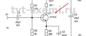
Charging block
This power supply begins to function immediately after assembly. Its basic options boil down to setting the operating charging current and the thresholds at which the SC is triggered. When the device is connected, a light diode lights up, positioning the voltage supply. During the charging process, the red light diode must light continuously, which will go out after the battery is fully charged.
Charging block
The input voltage from the power supply is adjusted by R2, and the charging current is set using R4. The adjustment is performed using a 160 Ohm resistor, connected in parallel to the contacts that hold the battery. Transistor VT1 is placed on the radiator; KT814B can be used instead. Such a circuit will need to be assembled on a board with a size of no more than 50x50 mm.
Crystal oscillator
This orthogonal pulse generator is implemented using a Russian comparator K544C3 operating at a harmonic clock of 32.768 Hz. The circuit will become operational in the spectrum of the incoming voltage 7-11V with the frequency set by the ZQ1 quartz. However, to operate such a device above 50.0 kHz, you will need to lower the value of R5-R6.
Generator
When the other terminal is closed with the 0-wire, the CN becomes connected according to the option with an open collector, and R7 becomes a load. Frequency adjustment is carried out jointly, using C1. Using R4, the generator is automatically started. By changing the value of R2, the impulse response changes.
Additional Information! By choosing capacitors C1 or C2, the generator can be used as a non-contact liquid sensor. For this purpose, you will need to use a microcontroller with software as a detector. However, it is also possible to use an additional comparator, which will record voltage deformations.
It follows that the comparator is capable of assigning actions to levels of values on its own inputs. When they differ, then, based on delta U, the output of the device changes its qualitative position. It is precisely these qualities that their creators use when developing a variety of electrical devices with an operational amplifier.
Introduction
Comments
JoJo 2011-09-01 07:33 Is it possible to add threshold adjustment to this scheme?
For example, replace some resistor with a potentiometer. Pashgan 2011-09-01 18:13 Unfortunately no. The dependence of Uthreshold on R will be nonlinear. In addition, changing the resistor will cause both thresholds to shift.
plv 2011-10-01 21:45 According to your calculations, I can’t calculate anything... I need help. Write to me Thanks in advance.
si-len-a 2012-03-01 19:30 Hello. Tell me, do I understand correctly that if a pulsating signal of -1.5 V is applied to the UIN2 input (LED), then there will be a constant signal at the UOUT output?
nordis 2012-12-19 14:35 Interesting. I just don’t understand why the tuning resistor cannot be connected in series with resistor R1. In addition to this, in my opinion, you can also use a thermistor. And to adjust the parameters there is a variable resistor +, -, Uin2. This is how my thermal control circuit works on an op-amp LM324
Pashgan 2012-12-19 20:33 I didn’t say it’s impossible. It’s possible, but it won’t be possible to linearly adjust the circuit’s response threshold with it.
sisrar 2013-01-21 10:35 Hello! When I entered the resistor values and voltages from your example, the threshold voltage values turned out to be 2.4444V and 2.5333V, while for you it was 1V and 2V. Help, please, what's wrong?
Pashgan 2013-01-21 10:53 The calculation uses the supply voltage and the positive saturation voltage of the op-amp. Are yours the same or different? And how do you check?
sisrar 2013-01-22 06:17 Thank you Pashgan for promptly answering my email and explaining what the problem was. Now everything worked out. The resistance values R1 and R2, equal to 1 kOhm, indicated at the beginning of the calculation were confusing. There is no need to pay attention to them, because... resistances R1 and R2 need to be found. I would erase R1 and R2 equal to 1 kOhm from the example and add to the text the derived equations for: R1 = U1 * R3 * (Uht / Ult - 1) / Usat; R2 = R1 / (U1 / Ult - R1 / R3 - 1).
Daniil 2013-03-04 09:49 Thank you, very detailed written! I just have 2 questions. 1) What are the maximum frequencies that such a comparator can use? Or does it depend on the op amp? As much as he can eat, the comparator can eat the same amount? 2) Is it possible for the signal levels to be 0 and 5V? I plan to apply a sine wave to the input of such a comparator, the peaks of which will be 0 and 5V, and I want to connect the output to a D-trigger to divide the frequency. And now I’m wondering whether the counter circuit will work correctly if it receives not from 0 to 5V, but from 0 to 4V, as calculated here?
Pashgan 2013-03-04 12:30 1) I can’t say for sure, I don’t know. Yes, it depends on the op-amp, but the rate of fire of the resulting comparator will definitely be lower than, for example, an op-amp amplifier circuit. Because the op amp takes time to come out of saturation. To process high-speed signals, it is better to use a comparator chip. 2) You need to look at which amplifier. The description usually specifies the range of input voltages. Lm358 at maximum allows you to do this, and in nominal mode the input voltage should be 1.5-2 volts less than the supply voltage. If you install limiting diodes, then in principle it is possible. As for the output voltage, you need to take the description of the meter and look at the minimum logical unit level for it.
Daniel 2013-03-04 13:16 Quoting Pashgan:
To process high-speed signals, it is better to use a comparator chip.
But there is a ready-made Schmitt trigger already wired into the case (for example, DIP14).
As I understand it, there is no need to calculate anything there anymore? Just take the description, look at the voltage levels and choose your own? Pashgan 2013-03-04 20:27 The calculation is exactly the same as with an operational amplifier. Only the comparator gives the output the full signal swing - from zero to U power. It has an open collector transistor at its output, which is pulled up to the power supply positive through a resistor.
Ra 2013-09-09 20:13 The article is good, according to the calculations, everything worked out in principle, there is only one question: Is the Schmitt Trigger circuit shown at the very beginning some kind of option with different set thresholds, or a Multivibrator? The designations are confusing...
Pashgan 2013-09-09 20:55 This is a common op-amp comparator circuit. What's confusing? Battery, resistors and op-amp.
Ra 2013-09-09 21:35 I confused the battery with a capacitor))) sorry, a little blind. Question on the topic, I couldn’t figure it out: How to find the output voltage with already known resistances and voltages at the inputs? Using the found values as an example. I mentioned this in passing in my previous article, but I can’t find it anywhere.
Pashgan 2013-09-10 07:14 For this scheme? In fact, it has only two output voltages, which are determined by the input voltage and specified thresholds.
Dimidrol 2014-02-13 17:30 Thank you! Very informative! 
dima 2015-12-17 13:41 I assembled the diagram. It turns out that if 0 volts are applied to UIN2 in the circuit, then the output will be 5 volts. If you apply 5 Volts, the output will be 0 Volts. It turns out that the Schmitt trigger on the op-amp inverts the signal? For some reason it works like this for me.
Refresh comments list RSS feed for comments to this post
You do not have sufficient rights to comment.
JComments