It often happens that a problem cannot be solved because the necessary formula is not at hand. Deriving a formula from the very beginning is not the fastest thing, but every minute counts for us.
Below we have collected together the basic formulas on the topic “Electricity and Magnetism”. Now, when solving problems, you can use this material as a reference so as not to waste time searching for the necessary information.
Daily newsletter with useful information for students of all directions - on our telegram channel.
Magnetism: Definition
Magnetism is the interaction of moving electric charges through a magnetic field.
A field is a special form of matter. Within the standard model, there are electric, magnetic, electromagnetic fields, a nuclear force field, a gravitational field and the Higgs field. Perhaps there are other hypothetical fields that we can only guess about or not guess at all. Today we are interested in the magnetic field.
Magnetic induction vector module
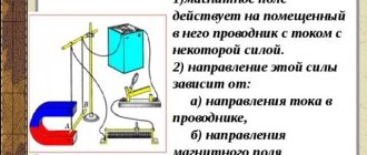
To determine the magnitude of the MI vector, you need to know its module. How is the magnitude of the magnetic induction vector (gradient) determined? This can be understood using a small model as an example. If you place a horizontally suspended conductor in the field of a horseshoe magnet, then the magnetic field of the magnet will act only on the area located in the interpolar gap. The force F→ acting on this section will be directed at right angles to the induction lines and the conductor itself. It reaches its maximum when the ort MI is located perpendicular to the conductor.
Magnetic induction
Just as charged bodies create an electric field around themselves, moving charged bodies generate a magnetic field. The magnetic field is not only created by moving charges (electric current), but also acts on them. In fact, a magnetic field can only be detected by its effect on moving charges. And it acts on them with a force called the Ampere force, which will be discussed later.
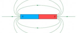
Magnetic field image using field lines
Before we start giving specific formulas, we need to talk about magnetic induction.
Magnetic induction is a force vector characteristic of a magnetic field.
It is designated by the letter B and is measured in Tesla ( T ). By analogy with the strength for the electric field E, magnetic induction shows the force with which the magnetic field acts on the charge.
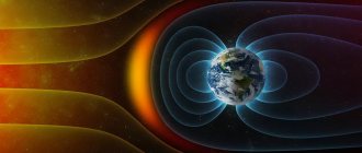
By the way, you will find many interesting facts on this topic in our article about the theory of magnetic field and interesting facts about the Earth’s magnetic field.
How to determine the direction of the magnetic induction vector? Here we are interested in the practical side of the issue. The most common case in problems is a magnetic field created by a conductor with current, which can be either direct, or in the shape of a circle or a coil.
To determine the direction of the magnetic induction vector, there is a right-hand rule . Get ready to engage abstract and spatial thinking!
If you take the conductor in your right hand so that the thumb points in the direction of the current, then the fingers curled around the conductor will show the direction of the magnetic field lines around the conductor. The magnetic induction vector at each point will be directed tangentially to the lines of force.
What are magnetic induction lines
The magnetic field is determined by the intensity at each point in its space. Curves connecting field points with equal magnitude strengths are called magnetic induction lines. The magnetic field strength at a specific point is a force characteristic and to evaluate it, the magnetic field vector B is used. Its direction at a specific point on the magnetic induction line is tangential to it.
If a point in space is affected by several magnetic fields, then the intensity is determined by the summation of the magnetic induction vectors of each active magnetic field. In this case, the intensity at a specific point is summed modulo, and the magnetic induction vector is defined as the sum of the vectors of all magnetic fields.
Despite the fact that magnetic induction lines are invisible, they have certain properties:
Ampere power
's imagine that there is a magnetic field with induction B. l in it , through which a current of force I , then the field will act on the conductor with a force:
This is the Ampere force . Angle alpha is the angle between the direction of the magnetic induction vector and the direction of the current in the conductor.
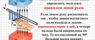
The direction of the Ampere force is determined by the left hand rule: if you position your left hand so that the lines of magnetic induction enter the palm, and the outstretched fingers indicate the direction of the current, the extended thumb will indicate the direction of the Ampere force.
Magnetic field strength
The ratio of magnetic induction to the product of magnetic permeabilities µ × µ is called magnetic field strength and is denoted by the letter H:
The last equation relates two magnetic quantities: induction and magnetic field strength.
Let's find the dimension H:
Sometimes another unit of measurement of magnetic field strength is used - the oersted (er):
The magnetic field strength H, like the magnetic induction B, is a vector quantity.
A line tangent to each point of which coincides with the direction of the magnetic induction vector is called magnetic induction line or magnetic induction line .
Lorentz force
We found out that the field acts on a current-carrying conductor. But if this is so, then initially it acts separately on each moving charge. The force with which a magnetic field acts on an electric charge moving in it is called the Lorentz force . What is important here is that the magnetic field does not act on stationary charges.
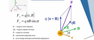
So, a particle with charge q moves in a magnetic field with induction B at speed v , and alpha is the angle between the particle velocity vector and the magnetic induction vector. Then the force that acts on the particle is:
How to determine the direction of the Lorentz force? According to the left hand rule. If the induction vector enters the palm and the fingers point in the direction of the velocity, then the bent thumb will show the direction of the Lorentz force. Note that this is how the direction is determined for positively charged particles. For negative charges, the resulting direction must be reversed.
If a particle of mass m flies into the field perpendicular to the induction lines, then it will move in a circle, and the Lorentz force will play the role of a centripetal force. The radius of the circle and the period of revolution of a particle in a uniform magnetic field can be found using the formulas:
Magnetic induction vector. Ampere force and Lorentz force
When current passes through a conductor, a magnetic field is formed around it. The vector characteristic of the magnetic field is called magnetic induction vector . This field has an orienting effect on the frame with current placed in the field. This action of a magnetic field on a frame with current or a magnetic needle can be used to determine the direction of the magnetic induction vector. The direction shown is the north pole N of the magnetic needle. To determine the direction of the magnetic induction vector of the field created by a straight conductor carrying current, use the gimlet rule: if the direction of the translational movement of the gimlet coincides with the direction of the current in the conductor, then the direction of rotation of the gimlet handle indicates the direction of the magnetic induction vector.
direction of the magnetic field vector of a straight conductor carrying current.
If a current-carrying conductor is placed between the poles of a horseshoe magnet, it will be pulled in or pushed out of the magnet's field. The law defining the force acting on a separate small section of a conductor was established in 1820 by A. Ampere.
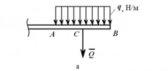
The force of a uniform magnetic field on a current-carrying conductor is directly proportional to the current strength, the length of the conductor, the magnitude of the magnetic field induction vector, and the sine of the angle between the magnetic field induction vector and the conductor:
F=BIℓ. sin α - Ampere's law .
- The Ampere force is maximum if the magnetic induction vector is perpendicular to the conductor.
- If the magnetic induction vector is parallel to the conductor, then the magnetic field has no effect on the current-carrying conductor, i.e. Ampere's force is zero.
Direction of Ampere's force (left hand rule) If the left hand is positioned so that the perpendicular component of vector B enters the palm, and the four extended fingers are directed in the direction of the current, then the thumb bent 90° will show the direction of the force acting on the current-carrying conductor.
The macroscopic manifestation of the Lorentz force is the Ampere force. Let us write down the force acting on one particle. If a charged particle flies into a magnetic field with a speed , it is acted upon by a force from the magnetic field, which is called the Lorentz force: , a
– the angle between the vectors and .
- In a uniform magnetic field directed perpendicular to the velocity vector, under the influence of the Lorentz force, a charged particle will move uniformly in a circle of constant radius r . The Lorentz force in this case is a centripetal force:
- If a charged particle moves in a magnetic field so that the velocity vector makes an angle a , then the trajectory of the particle is a helical line with radius r.
If you position your left hand so that the component of magnetic induction, perpendicular to the speed of the charge, enters the palm, and the four extended fingers are directed along the movement of the positive charge, then the thumb bent by 900 will indicate the direction of the Lorentz force Fl
.
Interaction of currents
Let's consider two cases. The first is that current flows through a straight wire. The second is in a circular turn. As we know, current creates a magnetic field.
In the first case, the magnetic induction of a wire with current I at a distance R from it is calculated by the formula:
Mu is the magnetic permeability of a substance, mu with index zero is the magnetic constant.
In the second case, the magnetic induction in the center of a circular coil with current is equal to:
Also, when solving problems, the formula for the magnetic field inside the solenoid can be useful. A solenoid is a coil, that is, many circular turns with current.
Let their number be N , and the length of the solenoid itself be l . Then the field inside the solenoid is calculated by the formula:
By the way! For our readers there is now a 10% discount on any type of work
Magnetic induction of a straight conductor
As you know, the simplest magnetic field creates a straight conductor through which electric current flows. As I already said in the previous article, the lines of force of a given magnetic field are concentric circles located around the conductor.
Magnetic induction of a magnetic field created by a straight conductor carrying current.
To determine the magnetic induction B of a straight wire at point P , we introduce some notation. Since point P is located at a distance b from the wire, the distance from any point on the wire to point P is determined as r = b/sinα. Then the shortest conductor length dl can be calculated from the following expression
As a result, the Biot–Savart–Laplace law for a straight wire of infinite length will have the form
where I is the current flowing through the wire,
b is the distance from the center of the wire to the point at which the magnetic induction is calculated.
Now we simply integrate the resulting expression over dα in the range from 0 to π.
Thus, the final expression for the magnetic induction of a straight wire of infinite length will have the form
where μ0 is the magnetic constant, μ0 = 4π•10-7 H/m,
I – current flowing through the wire,
b is the distance from the center of the conductor to the point at which the induction is measured.
Magnetic flux and emf
If magnetic induction is a vector characteristic of a magnetic field, then magnetic flux is a scalar quantity, which is also one of the most important characteristics of the field. Let's imagine that we have some kind of frame or contour that has a certain area. Magnetic flux shows how many lines of force pass through a unit area, that is, it characterizes the intensity of the field. It is measured in Webers (Wb) and denoted F.
S – contour area, alpha ( perpendicular) to the contour plane and vector B.
When the magnetic flux through a loop changes, an emf equal to the rate of change of the magnetic flux through the loop. By the way, you can read more about what electromotive force is in another of our articles.
Essentially, the formula above is the formula for Faraday's law of electromagnetic induction. We remind you that the rate of change of any quantity is nothing more than its derivative with respect to time.
The opposite is also true for magnetic flux and induced emf. A change in current in the circuit leads to a change in the magnetic field and, accordingly, a change in the magnetic flux. In this case, a self-induction EMF arises, which prevents a change in the current in the circuit. The magnetic flux that penetrates the current-carrying circuit is called its own magnetic flux, is proportional to the current strength in the circuit and is calculated by the formula:
L is a proportionality coefficient called inductance, which is measured in Henry (H) . The inductance is affected by the shape of the circuit and the properties of the medium. For a coil with length l and number of turns N, the inductance is calculated by the formula:
Formula for self-induced emf:
Magnetic flux
The product of magnetic induction and the magnitude of the area perpendicular to the direction of the field (magnetic induction vector) is called the flux of the magnetic induction vector or simply magnetic flux and is denoted by the letter F:
Magnetic flux dimension:
that is, magnetic flux is measured in volt-seconds or webers.
A smaller unit of magnetic flux is the maxwell (µs):
Video 1. Ampere's hypothesis
Video 2. Magnetism and electromagnetism
Source: Kuznetsov M.I., “Fundamentals of Electrical Engineering” - 9th edition, revised - Moscow: Higher School, 1964 - 560 p.
Source
Magnetic field energy
Electricity, nuclear energy, kinetic energy. Magnetic energy is a form of energy. In physical problems, most often it is necessary to calculate the energy of the magnetic field of a coil. The magnetic energy of a coil with current I and inductance L is equal to:
Volumetric field energy density:
Of course, these are not all the basic formulas of the “electricity and magnetism” section of physics, but they can often help in solving standard problems and calculations. If you come across a problem with an asterisk, and you just can’t find the key to it, make your life easier and contact the student help service for a solution.
Physical meaning of magnetic induction
Physically, this phenomenon is explained as follows. The metal has a crystalline structure (the coil is made of metal). The crystal lattice of a metal contains electrical charges - electrons. If no magnetic influence is exerted on the metal, then the charges (electrons) are at rest and do not move anywhere.
As a result, an electric current arises in the metal. The strength of this current depends on the physical properties of the magnet and coil and the speed of movement of one relative to the other.
When a metal coil is placed in a magnetic field, the charged particles of the metal lattice (in the coil) are rotated at a certain angle and placed along the magnetic field lines.
The higher the strength of the magnetic field, the more particles rotate and the more uniform their arrangement will be.
Magnetic fields oriented in one direction do not neutralize each other, but add up, forming a single field.