Unified State Exam 2021 in Physics ›
A magnetic field is a special form of matter that exists around moving electric charges - currents.
The sources of the magnetic field are permanent magnets and current-carrying conductors. A magnetic field can be detected by the effect on a magnetic needle, a current-carrying conductor, and moving charged particles.
To study the magnetic field, a closed flat circuit with current is used (frame with current).
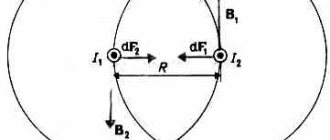
The rotation of a magnetic needle near a conductor through which current flows was first discovered by Oersted in 1820. Ampere observed the interaction of conductors through which current flowed: if the currents in the conductors flow in one direction, then the conductors attract, if the currents in the conductors flow in opposite directions, then they repel.
Properties of magnetic field:
- magnetic field is material;
- source and field indicator – electric current;
- the magnetic field is vortex - its lines of force (magnetic induction lines) are closed;
- the magnitude of the field decreases with distance from the field source.
Important! The magnetic field is not potential. Its work on a closed trajectory may not be equal to zero.
Magnetic interaction is the attraction or repulsion of electrically neutral conductors when an electric current is passed through them.
The magnetic interaction of moving electric charges is explained as follows: every moving electric charge creates a magnetic field in space that acts on moving charged particles.
The strength characteristic of the magnetic field is the magnetic induction vector \( \vec{B} \). The magnitude of the magnetic induction vector is equal to the ratio of the maximum value of the force acting from the magnetic field on a current-carrying conductor to the current strength in the conductor \( I \) and its length \( l \):
The designation is \( \vec{B} \), the SI unit is tesla (T).
1 T is the induction of a magnetic field in which a maximum force of 1 N acts on each meter of conductor length at a current of 1 A.
The direction of the magnetic induction vector coincides with the direction from the south pole to the north pole of the magnetic needle (the direction indicated by the north pole of the magnetic needle), freely established in a magnetic field.
The direction of the magnetic induction vector can be determined by the gimlet rule :
if the direction of translational movement of the gimlet coincides with the direction of the current in the conductor, then the direction of rotation of the gimlet handle coincides with the direction of the magnetic induction vector.
To determine the magnetic induction of several fields, the principle of superposition :
the magnetic induction of the resulting field created by several sources is equal to the vector sum of the magnetic induction of the fields created by each source separately:
A field at each point of which the magnetic induction vector is the same in magnitude and direction is called homogeneous.
The magnetic field is visually depicted in the form of magnetic lines or magnetic induction lines. A magnetic induction line is an imaginary line, at any point of which the magnetic induction vector is directed tangentially to it.
Properties of magnetic lines:
- magnetic lines are continuous;
- magnetic lines are closed (i.e. in nature there are no magnetic charges similar to electric charges);
- magnetic lines have a direction related to the direction of the current.
The density of the arrangement allows us to judge the size of the field: the denser the lines are, the stronger the field.
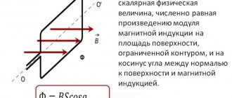
A flat closed circuit with current placed in a uniform magnetic field is acted upon by a moment of force \( M \):
where \( I \) is the current strength in the conductor, \( S \) is the surface area covered by the circuit, \( B \) is the magnitude of the magnetic induction vector, \( \alpha \) – the angle between the perpendicular to the contour plane and the magnetic induction vector.
Then for the module of the magnetic induction vector we can write the formula:
where the maximum moment of force corresponds to the angle \( \alpha \) = 90°.
In this case, the lines of magnetic induction lie in the plane of the frame, and its equilibrium position is unstable. The position of the frame with current will be stable in the case when the plane of the frame is perpendicular to the lines of magnetic induction.
Magnet interaction
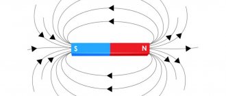
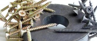
Permanent magnets are bodies that retain magnetization for a long time, that is, creating a magnetic field.
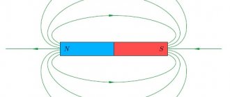
The main property of magnets is to attract bodies made of iron or its alloys (for example steel). Magnets can be natural (made from magnetic iron ore) or artificial, which are magnetized iron strips. The areas of a magnet where its magnetic properties are most pronounced are called poles. A magnet has two poles: north \( N \) and south \( S \).
Important! Outside the magnet, magnetic lines leave the north pole and enter the south pole.
It is impossible to separate the poles of a magnet.
Explained the existence of a magnetic field in permanent magnets Ampere. According to his hypothesis, elementary electric currents circulate inside the molecules that make up a magnet. If these currents are oriented in a certain way, then their actions add up and the body exhibits magnetic properties. If these currents are randomly located, then their action is mutually compensated and the body does not exhibit magnetic properties.
Magnets interact: like magnetic poles repel, unlike ones attract.
Physical meaning of magnetic induction
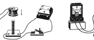
Physically, this phenomenon is explained as follows. The metal has a crystalline structure (the coil is made of metal). The crystal lattice of a metal contains electrical charges - electrons. If no magnetic influence is exerted on the metal, then the charges (electrons) are at rest and do not move anywhere.
If the metal comes under the influence of an alternating magnetic field (due to the movement of a permanent magnet inside the coil - namely movement ), then the charges begin to move under the influence of this magnetic field.
As a result, an electric current arises in the metal. The strength of this current depends on the physical properties of the magnet and coil and the speed of movement of one relative to the other.
When a metal coil is placed in a magnetic field, the charged particles of the metal lattice (in the coil) are rotated at a certain angle and placed along the magnetic field lines.
Magnetic field of a current-carrying conductor
An electric current flowing through a current-carrying conductor creates a magnetic field in the space surrounding it. The greater the current passing through the conductor, the stronger the magnetic field that arises around it.
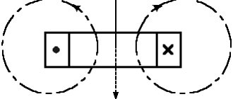
The magnetic lines of force of this field are located in concentric circles, in the center of which there is a current-carrying conductor.
The direction of the magnetic field lines around a current-carrying conductor is always in strict accordance with the direction of the current passing through the conductor.
The direction of magnetic field lines can be determined by the gimlet rule : if the translational movement of the gimlet (1) coincides with the direction of the current (2) in the conductor, then the rotation of its handle will indicate the direction of the magnetic field lines (4) around the conductor.
When the direction of the current changes, the magnetic field lines also change their direction.
As you move away from the conductor, the magnetic field lines are less frequent. Consequently, the magnetic field induction decreases.
The direction of current in a conductor is usually represented by a dot if the current is going towards us, and a cross if the current is directed away from us.
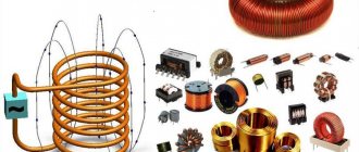
To obtain strong magnetic fields at low currents, they usually increase the number of current-carrying conductors and make them in the form of a series of turns; such a device is called a coil.
In a conductor bent in the form of a coil, the magnetic fields generated by all sections of this conductor will have the same direction inside the coil. Therefore, the intensity of the magnetic field inside the coil will be greater than around a straight conductor. When the turns are combined into a coil, the magnetic fields created by the individual turns add up. In this case, the concentration of field lines inside the coil increases, i.e., the magnetic field inside it intensifies.
The greater the current passing through the coil, and the more turns there are in it, the stronger the magnetic field created by the coil. The magnetic field outside the coil also consists of the magnetic fields of individual turns, but the magnetic field lines are not so densely located, as a result of which the intensity of the magnetic field there is not as great as inside the coil.
The magnetic field of a current-carrying coil has the same shape as the field of a straight permanent magnet: magnetic lines of force exit from one end of the coil and enter the other end. Therefore, a current-carrying coil is an artificial electric magnet. Typically, a steel core is inserted inside the coil to enhance the magnetic field; such a coil is called an electromagnet.
The direction of the magnetic induction lines of a current-carrying coil is found using the right-hand rule :
if you mentally clasp the current coil with the palm of your right hand so that four fingers indicate the direction of the current in its turns, then the thumb will indicate the direction of the magnetic induction vector.
To determine the direction of the magnetic field lines created by a turn or coil, you can also use the gimlet rule :
if you rotate the handle of the gimlet in the direction of the current in the coil or coil, then the translational movement of the gimlet will indicate the direction of the magnetic induction vector.
Electromagnets have found extremely wide application in technology. The polarity of an electromagnet (the direction of the magnetic field) can also be determined using the right-hand rule.
Tesla (unit)
| tesla | |
| Tl, T | |
| Magnitude | magnetic field induction |
| System | SI |
| Type | derivative |
Tesla
(Russian designation:
T
; international designation:
T
) - a unit of measurement of magnetic field induction in the International System of Units (SI), equal to the induction of such a uniform magnetic field in which per 1 meter of length of a straight conductor perpendicular to the magnetic induction vector, with a current of strength 1 ampere acts on a force of 1 newton.
In terms of the basic SI units, tesla is expressed as follows:
Through the derived SI units tesla is expressed by the relations:
- Wb/m2
- V s / m 2
- NA −1 m −1
In accordance with the SI rules regarding derived units named after scientists, the name of the unit tesla is written with a lowercase letter, and its designation “T” is written with a capital letter.
Relationships with other units of magnetic induction:
- 1 T = 10,000 gauss (CGS unit)
- 1 T = 1 10 9 gamma (unit used in geophysics)
The unit is named after the inventor Nikola Tesla. The tesla was introduced into the International System of Units (SI) by the decision of the XI General Conference on Weights and Measures in 1960, simultaneously with the adoption of the SI as a whole [1].
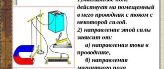
Ampere power
Ampere force is the force that acts on a current-carrying conductor in a magnetic field.
Ampere's law: a conductor with a current of force \( I \) of length \( l \), placed in a magnetic field with induction \( \vec{B} \), is acted upon by a force whose modulus is equal to:
where \( \alpha \) is the angle between the current-carrying conductor and the magnetic induction vector \( \vec{B} \).
The direction of the Ampere force is determined by the left hand rule : if the palm of the left hand is positioned so that the component of the magnetic induction vector \(B_\perp \) perpendicular to the conductor enters the palm, and four extended fingers indicate the direction of the current in the conductor, then the bent one The 90° thumb will show the direction of the Ampere force.
Ampere's force is not central. It is directed perpendicular to the lines of magnetic induction.
Ampere power is widely used. In technical devices, a magnetic field is created using conductors through which electric current flows. Electromagnets are used in an electromechanical relay for remotely turning off electrical circuits, a magnetic crane, a computer hard drive, a VCR recording head, a TV picture tube, and a computer monitor. Electric motors are widely used in everyday life, in transport and in industry. The interaction of an electromagnet with the field of a permanent magnet made it possible to create electrical measuring instruments (ammeter, voltmeter).
The simplest model of an electric motor is a current-carrying frame placed in the magnetic field of a permanent magnet. In real electric motors, instead of permanent magnets, electromagnets are used, and instead of a frame, windings with a large number of turns of wire are used.
Electric motor efficiency:
where \( N \) is the mechanical power developed by the engine.
The efficiency of the electric motor is very high.
Algorithm for solving problems about the action of a magnetic field on current-carrying conductors:
- make a schematic drawing on which to indicate a conductor or circuit with current and the direction of the field lines;
- mark the angles between the field direction and individual contour elements;
- using the left-hand rule, determine the direction of the Ampere force acting on a current-carrying conductor or on each element of the circuit, and show these forces in the drawing;
- indicate all other forces acting on the conductor or circuit;
- write down formulas for the remaining forces mentioned in the problem. Express forces in terms of the quantities on which they depend. If the conductor is in equilibrium, then it is necessary to write down the condition of its equilibrium (the sum of forces and moments of forces being equal to zero);
- write down Newton's second law in vector form and in projections;
- solve the resulting system of equations for an unknown quantity;
- check the solution.
Magnetic induction. Definition and description of the phenomenon.
Magnetic induction (denoted by the symbol B) is the main characteristic of a magnetic field (vector quantity), which determines the force of influence on a moving electric charge (current) in a magnetic field, directed in the direction perpendicular to the speed of movement.
Magnetic induction is defined as the ability to influence an object using a magnetic field. This ability is manifested when moves in a coil, as a result of which a current is induced (appears) in the coil, while the magnetic flux in the coil also increases.
Lorentz force
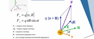
The Lorentz force is a force acting on a moving charged particle from a magnetic field.
Formula for finding the Lorentz force:
where \( q \) is the particle charge, \( v \) is the particle velocity, \( B \) is the magnitude of the magnetic induction vector, \( \alpha \) is the angle between the particle velocity vector and the vector of magnetic induction.
The direction of the Lorentz force is determined by the left hand rule : if the palm of the left hand is positioned so that the component of the magnetic induction vector \( B_\perp \) perpendicular to the conductor enters the palm, and four extended fingers indicate the direction of the velocity of the positively charged particle, then the bent at 90° the thumb will show the direction of the Lorentz force.
If the charge of the particle is negative, then the direction of the force is reversed.
Important! If the velocity vector is co-directed with the magnetic induction vector, then the particle moves uniformly and rectilinearly.
In a uniform magnetic field, the Lorentz force bends the trajectory of a particle.
If the velocity vector is perpendicular to the magnetic induction vector, then the particle moves in a circle whose radius is equal to:
where \( m \) is the mass of the particle, \( v \) is the velocity of the particle, \( B \) is the magnitude of the magnetic induction vector, \( q \) is the charge of the particle.
In this case, the Lorentz force plays the role of a centripetal force and its work is zero. The period (frequency) of revolution of a particle does not depend on the radius of the circle and the speed of the particle. Formula for calculating the period of revolution of a particle:
Angular velocity of a charged particle:
Important! The Lorentz force does not change the kinetic energy of the particle and its velocity modulus. Under the influence of the Lorentz force, the direction of the particle's velocity changes.
If the velocity vector is directed at an angle \( \alpha \) (0° < \( \alpha \) < 90°) to the magnetic induction vector, then the particle moves along a helical line.
In this case, the particle velocity vector can be represented as the sum of two velocity vectors, one of which, \( \vec{v}_2 \), is parallel to the vector \( \vec{B} \), and the other, \( \vec {v}_1\), – is perpendicular to it. The vector \( \vec{v}_1 \) does not change either in magnitude or direction. The vector \( \vec{v}_2 \) changes in direction. The Lorentz force will impart an acceleration to the moving particle perpendicular to the velocity vector \( \vec{v}_1 \). The particle will move in a circle. The period of revolution of a particle in a circle is \( T \).
Thus, uniform motion along the induction line will be superimposed on circular motion in a plane perpendicular to the vector \( \vec{B} \). The particle moves along a helical line with a step \( h=v_2T \).
Important! If a particle moves in electric and magnetic fields, then the total Lorentz force is equal to:
The peculiarities of the movement of a charged particle in a magnetic field are used in mass spectrometers - devices for measuring the masses of charged particles; particle accelerators; for thermal insulation of plasma in Tokamak installations.
Algorithm for solving problems about the action of a magnetic (and electric) field on charged particles:
- make a drawing, indicate the magnetic (and electric) field lines on it, draw the vector of the initial velocity of the particle and note the sign of its charge;
- depict the forces acting on a charged particle;
- determine the type of particle trajectory;
- expand the forces acting on a charged particle along the direction of the magnetic field and in the direction perpendicular to it;
- draw up the basic equation for the dynamics of a material point for each of the directions of force distribution;
- express forces through the quantities on which they depend;
- solve the resulting system of equations for an unknown quantity;
- check the solution.
Tesla (unit)
- Tesla (Russian designation: T; international designation: T) is a unit of measurement of magnetic field induction in the International System of Units (SI), equal to the induction of such a uniform magnetic field in which per 1 meter of length of a straight conductor perpendicular to the magnetic induction vector, with a current of 1 ampere produces a force of 1 newton.
Through the basic SI units, tesla is expressed as follows:
kg s−2 A−1 Through derived SI units, tesla is expressed by the relations:
NA−1·m−1In accordance with the SI rules concerning derived units named after scientists, the name of the unit tesla is written with a lowercase letter, and its designation “T” is written with a capital letter.
Relationships with other units of magnetic induction:
* 1 T = 10,000 gauss (CGS unit)
1 Tesla = 1⋅109 gamma (unit used in geophysics) The unit is named after the inventor Nikola Tesla. The tesla was introduced into the International System of Units (SI) by the decision of the XI General Conference on Weights and Measures in 1960, simultaneously with the adoption of the SI as a whole.
Related concepts
The International System of Units (SI) defines a set of seven basic units from which all other units of measurement are derived. These other units are called SI derived units and are also considered part of the standard.
Mentions in literature
Related concepts (continued)
Areas of different orders can be compared to provide a visual representation of their relativity. The data below should be considered as “typical values” and estimates have been rounded.
Source
Direct current
The magnetic field of a current-carrying conductor passes in a straight line, near which an MF occurs. The MF near the current-carrying conductor passes in a circular spiral. The direction of the magnetic field and current flows in one direction. And in which direction can be found by the gimlet rule: if the gimlet moves in the same direction as the electric charges in the conductor, then the direction of rotation of the gimlet handle corresponds to the direction of the MI vector.
Direct current MP - MP, the current of which flows through a long straight cable.
Direct current MF magnetic lines are curved lines in the shape of a circle that surround the conductor. In this case, in order to find the directions of the magnetic field lines, the right hand rule is used: if the conductor is held in the right hand, the thumb will be directed towards the current, and the other four fingers show the direction of the magnetic field lines.