Connecting machines in the panel - entrance from above or below?
The first thing I would like to start with is the correct connection of the machine in principle. As you know, a circuit breaker has two contacts for connection, movable and fixed. Which pin should be connected to the top or bottom? To date, there has been a lot of controversy regarding this matter. There are a lot of questions and opinions on this matter on any electrical forum.
Let's turn to regulatory documents for advice. What does the PUE say about this? In the 7th edition of the PUE, clause 3.1.6. said:
As you can see, the rules say that when connecting machines in a panel, the supply wire should, as a rule, be connected to fixed contacts. This also applies to all ouzo, difavtomat and other protection devices. From this entire clipping, the expression “as a rule” is not clear. That is, it seems to be as it should be, but in some cases there may be an exception.
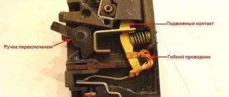
To understand where the moving and fixed contacts are located, you need to imagine the internal structure of the circuit breaker. Let's use the example of a single-pole circuit breaker to look at where the fixed contact is located.
Before us is an automatic machine of the BA47-29 series from iek. From the photo it is clear that its fixed contact is the upper terminal, and the moving contact is the lower terminal. If you look at the electrical symbols on the switch itself, you can also see that the fixed contact is on top.
Circuit breakers from other manufacturers have similar markings on the housing. Take, for example, a machine from Schneider Electric Easy9; its fixed contact is also located on top. For Schneider Electric RCDs, everything is similar on top there are fixed contacts and moving ones below.
Another example is safety devices from Hager. On the housing of the hager circuit breakers and RCDs you can also see symbols, from which it is clear that the fixed contacts are located on top.
Let's figure out from the technical side whether it matters how to connect the machine from above or below.
The circuit breaker protects the line from overloads and short circuits. When overcurrents occur, the thermal and electromagnetic releases located inside the housing react. From which side the power will be connected from above or below to trigger the releases there is absolutely no difference. That is, we can say with confidence that the operation of the machine is not affected by which contact the power is supplied to.
In truth, I should note that modular devices such as ABB, Hager and others allow power to be connected to the bottom terminals. For this purpose, the machines have special clamps designed for comb tires.
Why do the PUE recommend connecting to fixed contacts (top)? This rule was approved for general purposes. Any educated electrician knows that when performing work it is necessary to remove voltage from the equipment on which he will work. “Climbing” into the shield, a person intuitively assumes the presence of a phase on top of the machines. Having turned off the AV in the panel, he knows that there is no voltage at the lower terminals and everything that comes from them.
Now let’s imagine that the connection of the circuit breakers in the distribution board was carried out by an electrician, Uncle Vasya, who connected the phase to the lower AB contacts. Some time has passed (a week, a month, a year) and you have a need to replace one of the machines (or add a new one). Electrician Uncle Petya comes, turns off the necessary machines and confidently reaches into the voltage with his bare hands.
In the recent Soviet past, all machine guns had a fixed contact at the top (for example, AP-50). Nowadays, based on the design of modular AVs, you can’t tell where the movable and where the fixed contact is. For the ABs that we discussed above, the fixed contact was located on top. Where are the guarantees that Chinese machines will have a fixed contact located on top?
| Therefore, in the PUE rules, connecting the supply conductor to fixed contacts only means connecting to the upper terminals for the purposes of general order and aesthetics. I myself am a proponent of connecting power to the top contacts of the circuit breaker. |
For those who do not agree with me, a quick question is why in the electrical diagrams the power supply to the machines is connected precisely to the fixed contacts.
If we take, for example, a regular switch of the RB type, which is installed at every industrial facility, then it will never be connected upside down. Connecting power to switching devices of this kind relies only on the upper contacts. I turned off the switch and you know that the lower contacts are without voltage.
Installation of a differential circuit breaker in a distribution board
After selecting the connection diagram for the difavtomat, it is necessary to install it correctly and integrate it into the electrical network. Most often, the differential switch is mounted in the distribution panel where the electricity meter is installed, but sometimes a set of modular devices is installed in an additional distribution box, which is located indoors. In both cases, the rules and steps for connecting the device are the same. Let's consider this process using the example of installing a difavtomat in an additional electrical panel:
The technology for installing a difavtomat, at first glance, is very simple! But even such work can be completed with errors, which we will discuss below.
Is insulation coming into contact an error?
The most common mistake when installing a machine in an electrical panel is the presence of insulation that has gotten under the contact mount. It often happens that when installing circuit breakers or changing the box, after a while, the wiring inside it burns out. This happens when the ends of the wires are poorly stripped and particles of insulation get under the clamp, thereby worsening the tightness of the connection. In this regard, the insulating layer of the electrical wiring and insulation of the machine melts, which can cause a fire.
To avoid making such mistakes, it is necessary to thoroughly clean the ends of the wires connected to the automatic protection, and then make sure that there are no insulating particles left on the cleaned ends. After cleaning the insulation, form connections, tightening them well with a screw clamp.
Features of connection diagrams
To connect houses to the electrical network, self-supporting insulated wires are usually used, extending from overhead power lines. Despite the advantageous characteristics of SIPs, it is not recommended to connect them and install machines directly. This is explained by the fact that during long-term operation the aluminum conductors begin to overheat. In this case, the insulating layer melts, leading to fire or malfunction of the AV.
To avoid such cases, use special adapters connecting copper and aluminum wires. This circuit for connecting the machines will secure further maintenance of the electrical panel and increase the operational period of the RCD.
Based on the above, we can say that the installation of machines is not particularly difficult, so it can be done independently. The main thing is not to forget the basic rules for connecting AV: use conductors of the same cross-section, do not place the machine on the neutral conductor and make the connection in accordance with the PUE. It is also worth considering common mistakes and observing safety precautions when working with electric current.
Because You are not logged in. To come in.
Because The topic is archived.
I really like to turn off the power at the circuit breakers from below. There are a number of reasons for this.
a) it’s convenient for me b) it’s convenient to throw outgoing lines onto the machine from above c) saving on wires at the expense of the cost of tires d) mercantile interest. and so on.
And every time I hear the same thing
- we’ve been doing this for 30 years, but we don’t know why - here’s the taboo - about some moving parts. although the instructions say in black and white it doesn’t matter which side the power is on
Although I saw pedantic Germans switching off the power from below, and I do the same too))). 
not a question PUE 7 3.1.6 Automatic switches and plug-type fuses must be connected to the network so that when the fuse plug (circuit breaker) is unscrewed, the screw sleeve of the fuse (circuit breaker) remains without voltage. With one-way power supply, the connection of the supply conductor (cable or wire) to the protection device should, as a rule, be made to fixed contacts.
Most circuit breakers and ouzos known to me today have a fixed contact on the top. 
Good answer . killed two birds with one stone (a specific point in the pue and about moving parts).
I’ll correct the picture a little about the moving/non-moving contacts. 
This is not possible on all AVs. On Soviet industry automatic machines, for example (KEAZ and Kontaktor still make these), some are strictly defined to be connected from above, on some they can be connected from below, but at the same time the dynamic resistance to short-circuit currents drops by a factor of 1.5 - 2. So that’s where this myth comes from))), but on modern devices it doesn’t seem to matter at all, although I think with such connection options it’s better to still look at the instructions.
PS I’m writing from my wife’s account))) 
let's narrow the circle a little
my topic concerns ONLY AB
1) modular design for DIN rail 2) from 1 to 63 Amps inclusive 3) any manufacturer 
Well, in such a “narrow circle,” of course, there are no options.
I just wrote an assumption where the myth came from))) 
Upside down, you can also sketch out a million reasons to supply power from above. 1. We even draw electrical diagrams from top to bottom and from left to right. and the Krauts also have 2. the same power distribution cabinets (let’s take DC): input from above and division into sections, outgoing connections went down. because cables enter from the cable mezzanine from below (rarely from above from the shelves). 3. At my house, there is also entry and exit from above (food and outgoing), but nothing prevented me from starting the power supply from above on AB)), etc.
We’ve been doing it for 30 years and don’t know: we know. Traditionally, it has happened that when the machine is turned off, there should be no voltage from below. you can work calmly. too lazy to look, but PUE is not all regulatory documents, citizens are electricians. this is just the general part
I “liked” another thing more: at one military facility I came across domestically produced AVs whose status block contacts work crosswise (X). I’m seeing this for the first time, even at the factory people were confused about who assembled the cells and even the ABs themselves - GO.. Oh, it’s rare, they work every other time and not at their nominal value. now they do it in every village 
Why can’t you connect several wires of different cross-sections to one terminal?
Sometimes there is a need to install several machines powered by one core, and for this it is advisable to use special rails or comb buses. However, they are rarely available, so you have to use ordinary jumpers - pieces of wires connecting the power to the AB.
This connection can be made in the shield with your own hands. To do this, you will need jumpers made of electrical wire with an identical cross-sectional area. To make a jumper, it is not necessary to cut, clean and connect each piece to each other. It is enough to measure the required length so that it is enough to combine all the AB contacts, and then, having given the required shape, strip the wire at the bends that are inserted into the terminals of the machines. Thus, a complete, continuous jumper emerges.
It is not recommended to connect machines using wires of different sections. When the ends are fixed in the terminals, the thick wires will be tightened well, and the wires of a smaller cross-section located nearby will be weakened. Subsequently, the sheath of wires and AB contacts will begin to melt at this point, which can cause a fire.
When installing an AB in an apartment or private house, use wiring with a cross-section of 2.5 mm2. This is determined by the load, the amount of energy expended, and also indicates how many amperes the machine should be set to.
