Varieties of traditional and modern reinforcement bar connections
Current technical regulations distinguish three types of reinforcement connections:
- overlap connection without welding with determination of the bypass length by calculation depending on the diameter and class:
- straight reinforcement of periodic profile;
- the same with fastening the lining or transverse rods along the length of the overlap;
- with hooks, claws, loops at the end of steel profiles;
- welded butt joints, where the type of unit, as well as the designation of the weld, is determined in relation to the welding technology and operating conditions of the monolithic structure;
- connection using special couplings.
Welded and lap joints have been practiced for a long time; they have already become classics of concrete work with their pros and cons (high cost, time, excessive consumption of metal). Meanwhile, MSA technologies have been proving their effectiveness at facilities in Russia, near and far abroad for decades, gradually becoming widespread.
Connecting reinforcement without welding
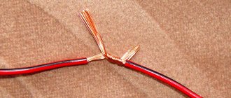
Connections of reinforcement bars in a reinforcement cage are divided into two types: butt and cruciform. Both types of connections can be made without welding. Cross-shaped connections are made by knitting with annealed wire or using connecting elements (plastic or wire fasteners). This process is described in more detail in the article “Knitting reinforcement”.
Non-welding connections of reinforcement joints in accordance with regulatory documents (clause 2.102 of SNiP 3.03.01-87 “Load-bearing and enclosing structures”) should be made:
- lap - “connection of reinforcing bars along their length without welding by inserting the end of one reinforcing bar relative to the end of the other” (Appendix B SNiP 52-01-2003);
- using crimp sleeves and screw couplings.
Weldless lap butt joint
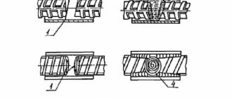
In accordance with clause 8.3.26 SP 52-101-2003, lap joints are made without welding:
- with straight ends (only for periodic profile bars);
- with straight ends of rods with welding or installation of transverse rods along the overlap length;
- with bends at the ends (legs, hooks, loops). For smooth rods, only hooks and loops can be used.
The reinforcement connection should not be placed in areas of greatest stress. In accordance with clause 8.3.27 SP 52-101-2003, lap joints without welding can be used for working reinforcement rods with a diameter of no more than 40 mm
.
Overlap length for reinforcement joints
The minimum length is determined in two ways: calculated and according to schedules. In regulatory documents you can find 2 options:
Option 1: in accordance with clause 2.46 of the Guidelines for the design of concrete and reinforced concrete structures made of heavy concrete (without prestressing) (Moscow Stroyizdat 1978):
- according to the formula: ln=(mn*( sa/ R
pr) + Dλn)d,
where sa is the stress in the reinforcement at the lap joint on the most stressed side.
m values
n and Dλn, as well as the minimum values
of l
n and λn for determining the length of the lap joint of reinforcing bars are given in the table:
| Joint operating conditions | periodic profile rods | smooth rods | ||||||
| Dλн | m n | λн | l n, mm | Dλн | m n | λн | l n, mm | |
| no less | no less | |||||||
| Joint in tensile concrete | 11 | 0,9 | 20 | 250 | 11 | 1,55 | 20 | 250 |
| Joint in compressed concrete | 8 | 0,65 | 15 | 200 | 8 | 1 | 15 | 200 |
- according to schedules:
Option 2: in accordance with clause 6.1 (taking into account section 5) of the Design Manual “Reinforcement of elements of monolithic reinforced concrete buildings” (Moscow 2007):
- according to the formula: ll
= α*
R
s
A
s/( η1η2
Rbt)u
s
*
(
As,cal
/
As,ef
),
Where:
α - for tensile reinforcement - 1.2; for compressed - 0.9;
R
s - calculated tensile strength for a given type of reinforcement (equal to 355 MPa for reinforcement of class A400 (A-III), 435 MPa for reinforcement of class A500C);
A
s and
u
s - area and perimeter of the cross section of the anchored rod (determined by the nominal diameter of the rod);
η1 – coefficient of influence of the type of surface of the reinforcement, is taken equal to: 1.5 - for smooth (class A240); 2.0 - for cold-deformed periodic profile (class B500); 2.25 - for bar reinforcement of a periodic profile of foreign production, hot-rolled and thermo-mechanically strengthened, which meets the requirements of foreign regulatory documents; 2.5 - for periodic profiles of Russian manufacturers according to GOST 5781-82, GOST 10884-94, GOST R 52544-2006, STO ASChM 7-93, TU 14-1-5254-94, except A500SP according to TU 14-1-5526 -2006; 2.8 - for class A500SP according to TU 14-1-5526-2006; η2 - coefficient influencing the size of the diameter of the reinforcement, is taken equal to: 1.0 - with diameter d
s≤32;
0.9 - with a diameter of 36 and 40 mm of all types; Rbt
—axial tensile strength of concrete;
As, cal
/
As,ef
- cross-sectional areas of the reinforcement, respectively, required by calculation with the full design resistance and actually installed.
- according to schedules:
Graphs for determining the overlap length of periodic profile reinforcing bars in tensile concrete
Graphs for determining the overlap length of periodic profile reinforcing bars in compressed concrete
If we compare the graphs of option 1 and option 2, we will see that option 1 provides for a shorter length of the butt joint of the lap reinforcement. This is explained by the fact that at the time of writing the “Guide to the design of concrete and reinforced concrete structures made of heavy concrete (without prestressing)” (1978), reinforcement with a ring periodic profile was mainly used in the USSR. At the time of the release of the Design Manual “Reinforcement of elements of monolithic reinforced concrete buildings” (2007), in the Russian Federation, along with bars with a ring profile, reinforcing bars with
crescent-shaped double-sided profile (“Europrofile”)
.
You can read more about the features of these types of profiles in the article “Foundation reinforcement: choosing reinforcement (continued).” Therefore, modern regulatory documents are a compromise solution for determining the basic anchorage length of reinforcement for both types of profiles. It should be noted that the design standards of other countries (where the “Europrofile” is predominantly used) provide for the anchorage length of the reinforcement to be 1.3-2 times higher than according to the building codes of the Russian Federation (see section 1.1 of the Manual).
Conditions for connecting reinforcement with an overlap without welding
In accordance with clause 6.1 of the Design Manual “Reinforcement of elements of monolithic reinforced concrete buildings” (Moscow 2007), the following conditions must be met:
- the relative amount of working tensile reinforcement of a periodic profile joined in one design section of an element should be no more than 50%, smooth reinforcement (with hooks or loops) - no more than 25%. By “one design section of an element” we mean its section with a length of 1.3 l
along the joining reinforcement (see Figure 1), i.e. reinforcement joints are located in the same design section if the centers of these joints are within the length of this section; - the force perceived by all transverse reinforcement placed within the joint must be at least half the force perceived by tensile working reinforcement joined in one design section of the element;
- the distance between the joining rods of the working reinforcement should not exceed a value equal to 4 d;
- the distance between adjacent lap joints (across the width of the reinforced concrete element) must be at least 2 d
and at least 30 mm; - the length of the bypass can be reduced, but not by more than 30% - if there are additional anchoring devices at the ends of the joined rods (bending the ends of the joined rods of a periodic profile, welding transverse reinforcement, etc.);
- the actual length of the bypass must be at least 20
d and at least 250 mm
.
In accordance with section 3.2. reference manual “Regulatory requirements for the quality of construction and installation work” (St. Petersburg, 2002) the length of the overlap (bypass) of the reinforcement must be at least: 40d for class A-I and A-II; 50d - for A-III fittings
.
Tweet
Share
{lang: 'ru'}
We recommend:
Classification of Mechanical Connections of Fittings
The current regulations classify ISAs according to the method and purpose of the connection. So the connections could be:
- threaded , due to a connecting cylinder with an internal conical or cylindrical thread connecting the ends, where a thread of the same profile is already made;
- pressed , when the ends of the profiles are connected by a steel cylinder, compressed by a hydraulic press, as a result of which the metal from which it is made is pressed between the ribs of the periodic profile;
- screw , in which the connection is made by a coupling, where a screw periodic profile, similar to a reinforcing one, is cut inside, as well as locknuts screwed onto steel rods;
- bolted , where the fixation of the connected reinforcement occurs due to bolts screwed through the coupling wall into the profile body, and their number depends on the amount of force perceived by the connection.
According to the purpose, according to the design solution of the connecting element, MSA can be:
- standard , connecting fittings of the same diameter, when at least one of them can rotate;
- transitional , similar to standard ones, but connecting fittings of different diameters;
- positional , connecting the fixed ends of steel profiles;
- welded : for joining reinforcement frames and metal structures.
These types of MSA are manufactured by domestic and foreign manufacturers; they are already used in practical construction.
Taper thread system
The connection of periodic profile reinforcement with a diameter from 12 to 40 mm of classes A400, A500 and A600 can be made using LENTON couplings with tapered threads. The system includes couplings:
- standard , for rods of the same diameter, when at least one of them can rotate;
- transitional for rods of different diameters, when at least one of them can rotate;
- positional , connecting fittings that are not capable of rotating;
- welded for attaching rods to metal structures. A conical thread is cut inside one end of the connecting element, and the other is prepared for welding;
- end (anchor) designed for anchoring reinforcement of reinforced concrete structures;
- combined with conical and cylindrical threads for bolting steel structures to concrete.
The use of tapered threads eliminates the possibility of damage before complete mating. The connection can be made equally quickly for horizontal and vertical reinforced concrete structures. To do this, first screw the coupling onto one end, then insert the second into the coupling, and then tighten it 4-5 turns with a force of 40 to 350 Nm.
MSA based on LENTON technology were used in the reinforcement of monolithic reinforced concrete structures of high-rise office buildings of the Moscow City complex, Abu Dhabi Plaza (Astana), the Central section of the Western High-Speed Diameter, the Lakhta Center complex (St. Petersburg), Leningrad, Beloyarsk nuclear power plants, the cable-stayed bridge “Golden Horn” (Vladivostok), the Olympic stadium “Fisht” (Sochi), and other objects.
The capabilities of the LENTON system made it possible to develop cryogenic couplings used to reinforce concrete structures of tanks for storing liquefied gas at a temperature of 160°C. The use of such elements made it possible to continue reinforcing work in winter conditions at temperatures below -40° during construction, thanks to which the work was completed on schedule.
Assembly and welding of reinforcement bars
Reinforcement in concrete structures
should be provided:
- in places where there is a sharp change in the cross-sectional dimensions of elements
; - in places where the height of the walls
(in an area of at least
1 m
); - in concrete walls under and above the openings
of each floor; - in structures
exposed to dynamic loads.
For reinforced concrete
weakly reinforced
elements of a tensile zone
-
the cross-sectional area of longitudinal tensile reinforcement
must be increased by at least
15%
.
Structural reinforcement
is not provided if, according to calculations
taking into account the resistance of the tensile concrete zone
, reinforcement is not required and experience has proven the possibility of transporting and installing such elements without reinforcement.
For the foundation, you also need to choose the right reinforcement
ATTENTION! When assembling reinforcement cages
The alignment of the rods
must be strictly observed .
The displacement should not exceed 0.1d
, and the fracture at the junction should not exceed
3°
.
Correspondence of reinforcement location
its design position should be ensured by installing plastic
clamps, washers
made of fine-grained concrete, etc.
READ ALSO: Repair of waterproofing of foundations and basement walls
At intersections of reinforcement in frames
:
- rods of piece reinforcement
up to
d=25 mm
are fastened by spot welding, ligation with knitting wire or using special connecting elements, and
rods d=25 mm and above
- by arc welding; - To obtain cross connections of two or three intersecting rods d=3...40 mm
from steel of class
A-I, A-II, A-III
and wire
d=3...8 mm
of classes
B-I and Bp-I
, spot contact welding is used.
ATTENTION! At least 50% of all intersections
, including the obligatory intersection
of rods with clamps (in the corners)
.
Length of fittings
from the concrete body between the joined rods there must be at least
150 mm
with normal gaps and
100 mm
when using an insert.
With increased gaps between joined rods
It is allowed to use one insert from reinforcement of the same class and diameter.
Minimum distances
in the clearance
between the reinforcement bars
in height and width of the section should:
- ensure the joint operation of reinforcement with concrete and are assigned taking into account the convenience of laying and compacting the concrete mixture;
- for prestressed structures,
compression of concrete
and the dimensions of tensioning equipment (jacks, clamps, etc.) must also be taken into account
In elements
manufactured using bayonet vibrators, free passage between the reinforcing bars of the vibrator tips that compact the concrete mixture must be ensured.
Clear distances between individual bars of longitudinal non-prestressing reinforcement
, as well as between
the longitudinal rods of adjacent flat welded frames,
no less than the largest diameter of the rods
should be taken , as well as:
a) if the rods are being concreted
occupy
a horizontal or inclined
position - not less than:
- for lower reinforcement
- at least
25 mm
; - for upper reinforcement
- at least
30 mm
; - when the lower reinforcement in more than two rows in height,
the distance
between the rods in the horizontal direction
(except for the rods of the two lower rows) must be
at least 50 mm
;
b) if the rods are being concreted
occupy
a vertical position
- at least
50 mm
;
with systematic control of the fractionation of concrete aggregates,
this distance can be reduced
to 35 mm
, but it must be at least
one and a half times the largest size of the coarse aggregate
.
In cramped conditions
It is allowed to place
reinforcement bars in pairs
(without a gap between them).
NOTE: Clear distance between periodic profile bars
taken
according to the nominal diameter
without taking into account protrusions and ribs.
When reinforcing continuous slabs
with welded rolled mesh,
to transfer
lower rods to the upper zone
near intermediate supports .
The distances between the axes of the working rods
in the middle span of the slab and above the support
(at the top) should be no more than
200 mm
for a slab thickness of
up to 150 mm
and no more than
1.5h
for a slab thickness of
over 150 mm
, where
h
is the thickness of the slab.
Periodic profile bars
, as well as
smooth rods
,
in welded frames and meshes
, are made
without hooks
.
The stretched smooth rods of knitted frames and nets
must end
in hooks, tabs or loops
.
For all surfaces of reinforced concrete elements
, near which
longitudinal reinforcement
transverse reinforcement
should also be provided , covering
the outer longitudinal bars
.
In this case, the distances between the transverse rods
at each surface of the element should be
no more than 600 mm
and no more than
twice the width of the edge of the element
.
Transverse reinforcement
It is allowed not to place
bendable elements (
150 mm
or less)
at the edges of thin ribs one longitudinal rod or welded frame
.
When reinforcing eccentrically compressed elements
with flat welded frames, the two outer frames
(located at opposite faces) must be connected to each other to form
a spatial frame
.
To do this, at the edges of the element normal to the plane of the frames
transverse rods
must be placed , welded by contact welding
to the corner longitudinal rods of the frames
, or
clamps
(Fig. 4) connecting these rods must be installed at the same distances as the transverse
rods of flat frames
.
In reinforcing elements
that work in bending with torsion,
knitted clamps
must be closed with reliable anchoring at the ends.
And with welded frames
, all
transverse rods
in both directions must be welded
to the corner longitudinal rods
, forming
a closed loop
.
, equal strength of connections and clamps
must be ensured .
READ ALSO: Recommendations for repairing the foundation and basement of a house
Protective coatings for fittings
(if they are provided for by the project) are applied in accordance with
SNiP 3.03.01-87
.
The integrity of the protective layer of reinforcement
is checked before concreting, and any defects found are eliminated.
Dextra Bartec system with parallel thread
The “DEXTRA Bartec” coupling connection from PSK Group provides an equal-strength joint for reinforcement with a diameter of 12 to 65 mm through the use of a coupling with an internal metric thread that connects the ends of the rods with a cut thread of the same profile. The main element of the system is BARTEK couplings:
- standard, connecting rods of the same diameter with the possibility of rotation of at least one end;
- transitional for joining fittings of different diameters with the possibility of rotation of at least one end;
- positional, when neither end of the rod can rotate. In this case, the coupler is completely screwed onto one end, and after docking it is unscrewed, connecting both ends. To reduce the area of weakened cross-section, threading is performed in the following sequence:
- cutting rods to length;
- increasing the initial end diameter using cold pressing;
- rolling metric threads on the pressed end.
- MSA with metric thread allows you to reinforce walls, columns, as well as beams and slabs.
The Bartec system has proven its effectiveness in the reconstruction of the Oktyabrsky tunnel, the laying of Kazan metro lines, the construction of the Belarusian, Kursk and Novovoronezh nuclear power plants, residential buildings and public buildings in Moscow, Kazan and the cities of the Southern Federal District, as well as in the construction of the first Bangladeshi nuclear power plant "Rooppur" and other special complex objects.
PRESKO system with crimp couplings
The MSA “PRESKO” system forms reinforcement joints with a diameter of 18 to 40 mm using standard and transition couplings that connect the ends of rods of the same or different diameters by crimping them without preliminary preparation of the ends. During compression, the metal of the connecting element fills the differences in the periodic profile, thereby forming an equal-strength joint. Such a joint is more economical compared to connections with bypasses, and compared to welding, it is less labor-intensive, and also does not require a highly qualified specialist to perform.
The connection device using coupling compression consists of two operations:
- installation of the PRESCO connecting element at the joint in the design position;
- crimping the joint using a mobile hydraulic unit.
PRESKO crimp couplings were used in the construction of the capital's Hanoi-Moscow business center, the Rostov Arena football stadiums, the VTB Arena complex, facilities in the satellite city of Kazan "Innopolis", the Akhmat Tower, the Grozny Mall shopping center in capital of Chechnya.
Assembly and welding of installation connections of steel structures
Weldable surfaces of the structure
and
the welder's
must be protected from rain, snow, and wind. At ambient temperatures below -10°C, it is necessary to have an inventory room for heating near the welder’s workplace; at temperatures below -40°C, a warming house must be equipped.
Voltage fluctuations in the electrical current supply network
, to which the welding equipment is connected, should not exceed
±5% of the nominal value
.
Equipment
for automated and manual
multi-station welding
should be powered from a separate feeder.
Types of welded joints
and methods for welding
reinforcement and embedded parts
should be prescribed taking into account the operating conditions of the structure, the weldability of steel, the technical and economic indicators of the connections and the technological capabilities of the manufacturer in accordance with GOST 14098-85.
Welding of structures
when enlarged and in the design position, it should be done after checking the correct assembly.
For welding rods
from steel
of all classes, except AI
, electrodes of grade
UONI 13/55U
or similar are used:
- reinforcement up to d=36 mm
is welded with electrodes
d=4...5 mm
, - fittings d=40 mm and above
- with electrodes
d=5...6 mm
.
Welding is performed without interruption until the joint is completely welded, making sure to fill the craters
.
Then the flange seams are welded. The current strength during manual welding
ranges from
220A
at
d=20 mm
, to
330A
at
d=40 mm
.
Flank weld dimensions
must be:
- height h=0.25d
, but not less than
4 mm
, - width b=0.5d
, but not less than
10 mm
.
The edges of the welded elements
of steel frames
at the locations of the seams and the surfaces adjacent to them must be cleaned to remove rust, grease, paint, dirt, moisture, etc.:
- for manual or mechanized arc welding
- at least
20 mm
; - for automated types of welding
- at least
50 mm
; - as well as the junction of the initial and output strips
.
The number of calcined welding materials at the welder’s workplace should not exceed half-shift requirements. Welding materials should be kept in conditions that prevent them from getting wet.
ATTENTION! Manual and mechanized arc welding of structures
it is permitted to perform without heating at the ambient temperature given in
SNiP 3.03.01-87
.
At lower temperatures, welding
should be carried out with preliminary local heating of the steel to
120...160°C
in a zone
100 mm
on each side of the joint.
Table 1: It is allowed to carry out manual and mechanized arc welding of structures without heating at ambient temperatures.
| p/p | Thickness of welded elements | Minimum permissible ambient temperature when welding structures | ||||
| lattice | sheet volumetric and solid wall | lattice | sheet volumetric and solid wall | lattice and sheet | ||
| of steel | ||||||
| carbon | low-alloy with yield strength, MPa (kgf/mm²) | |||||
| <390 (40) | >390 (40) | |||||
| 1 | 2 | 3 | 4 | 5 | 6 | 7 |
| 1 | <16 mm | -30°С | -30°С | -20°С | -20°С | -15°С |
| 2 | 16mm <25mm | — | — | — | — | 0°C |
| 3 | 16mm <30mm | -30°С | -20°С | -10°С | 0°C | For a thickness of more than 25 mm, local preheating should be carried out regardless of the ambient temperature |
| 4 | 30mm <40mm | -10°С | -10°С | 0°C | 5°C | |
| 5 | >40 mm | 0°C | 0°C | 5°C | 10°C | |
Automated arc welding
Submerged arc is allowed to be produced without heating at the ambient temperature given in Table 2.
Table 2: It is permitted to perform automated submerged arc welding of structures without heating at ambient temperatures.
| p/p | Thickness of the welded element | Minimum permissible ambient temperature when welding steel structures | |
| carbon | low alloy | ||
| 1 | 2 | 3 | 4 |
| 1 | <30 mm | -30°С | -20°С |
| 2 | >30 mm | -20°С | -10°С |
Joint seams
Sheet volumetric and solid-walled structures with a thickness of more than
20 mm
during
manual arc welding
should be performed in ways that ensure a reduction in the cooling rate of the welded joint:
- sectional reverse stage,
- sectional double layer,
- cascade,
- sectional cascade.
With double-sided manual
or mechanized
arc welding
of butt, T and corner joints with full penetration, it is necessary to remove its root from the reverse side to clean, defect-free metal before making a seam.
In case of a forced break in work, mechanized arc or automated submerged arc welding
it is allowed to resume after cleaning the crater and the adjacent end section of the weld with a length of 50...80 mm from slag. This area and the crater must be completely covered with a seam.
READ ALSO: Concrete curing: concrete curing method
Surfaces of the structure to be welded
and completed seams of welded joints after completion of welding must be cleaned of slag, splashes and deposits of molten metal.
Quality of potholders
, welded joints of fastenings of assembly and installation devices, determined by external inspection, must not be lower than the quality of the main welded joints.
Defective areas
Weld seams should generally be removed in one of the following ways:
- mechanized cleaning (abrasive tool)
- or mechanized cutting.
All surface burns
The base metal with a welding arc should be cleaned with an abrasive tool
to a depth of 0.5...0.7 mm
.
Main types of welds
, structural elements and dimensions of welded joints made of steels made by manual and arc welding are established by GOST 5264-80 and GOST 11534-75.
Main types, structural elements and dimensions of welded joints made of sheet, strip and profile metal used in embedded parts
and
connecting products
of reinforced concrete structures must meet the requirements of GOST 5264 and GOST 8713.
Welded joints
rod reinforcement and reinforcing wire with a diameter of
3 mm or more
, welded connections
of rod reinforcement with rolled
a thickness
of 4 to 30 mm
, performed in the manufacture
of reinforcement
and
embedded products
of reinforced concrete structures, as well as during the installation of prefabricated and construction of monolithic reinforced concrete structures, must meet the requirements of GOST 14098 -91.
LENTON LOCK bolted coupling system
The MCA system on bolted couplings “LENTON LOCK” manufactured by the American company (Pentair) is universal. It can be used for joining reinforcing bars with a diameter from 12 to 44 mm, periodic or smooth, in the factory or on the construction site, of the same or different diameters without preliminary preparation of the ends. The connection is made by clamping the ends of vertical or horizontal reinforcement in a standard or transition coupling with bolts screwed into the wall of a steel cylinder, while the bolt heads self-cut when the required tightening torque is reached. Depending on the diameter of the connecting rods, from 6 to 12 bolts are screwed into the connecting element.
MSA on LENTON LOCK couplings have already proven the possibility of being used by domestic builders at the Novopolotsk Refinery facilities, when reinforcing monolithic structures of the IQ-quarter skyscraper complex, during the reconstruction and expansion of the Moscow Ring Road, as well as at other facilities.
Non-welding methods for connecting reinforcement
When installing fittings
from individual rods, reinforcing
meshes and frames with
additional rods, cross connections of reinforcement rods at the places of their intersection should be fastened with knitting wire or using wire clamps (Fig. 5).
Fasteners
made from wire grade P-I or P-II with diameter d=1.6...1.8 mm.
With their help, one- and two-sided connections
of reinforcing bars with a diameter of d=5...32 mm can be made. The clamps are made on a universal bending machine equipped with special equipment.
The ends of the rods
in non-welded joints from smooth profile reinforcement in the tension zone are made
with hooks
, and from periodic profile steel -
without hooks
. At the junction points, the rods must be tied with wire in a double knot.
Distance between joints
located
in different sections of the frame
must be no less than the length of the overlap or half-lap.
The joints of the reinforcement
should not coincide with the bending points of the rods.
The consumption of steel wire
d=1 mm...1.5 mm for knitting
1 ton of reinforcement is
4...5 kg
; if the diameter of the rods is over d=25 mm, they should be
fastened by arc welding
.
The length of the bypass of knitting reinforcing mesh and frames
in working joints made overlapping without welding, in the tension zone - from rods with a nominal diameter d according to Table 4.
Systems using Flimu (DSI), GEWI couplings
The MSA “Flimu” system involves crimping the ends of the joined profiles with a connecting coupling as a result of pulling a special crimp ring along it. The internal size of the ring is smaller than the external size of the connecting cylinder, which forces the metal from which it is made to fill the profile. To pull the ring through, manual equipment designed specifically for use in construction environments is used. The German “GEWI” system is based on the use of high-strength rods with left-hand trapezoidal threads along the entire length. Connecting elements with appropriate internal threads allow for quick joining.
Which reinforcement connections are best for ASG?
Much work on the introduction of innovative ISAs into mass construction in Russia and the countries of the Customs Union is carried out by the NIIZhB named after. Gvozdeva and group (GK PSK). They jointly developed design and technological documentation for the use of a number of MSA systems in the production of reinforcement works, incl. at particularly dangerous, technically complex, unique objects. Each of them already has experience of practical use on residential, warehouse, industrial buildings, bridges, overpasses, built in Russia and abroad.
The variety of objects already built using MSA shows the applicability of these technologies for use in mass construction when reinforcing structures for various purposes that can withstand almost any effort, and most importantly, the PSK Group guarantees an increase in the speed of the entire complex of reinforcement work when implementing any of the selected technological systems. PSK's trained fitting engineers will not only help with the implementation of the selected technological system, but are also ready to perform all the work on cutting or rolling threads on fittings using their own equipment.