Where you should definitely start connecting the engine: 2 important time-tested points
Before turning on any electric motor for the first time, it is necessary to clarify its structure: the design of the stator and rotor, the condition of the bearings.
From my own and other people’s experience, I can assure you that it is easier to loosen a few nuts, inspect the internal structure, identify defects at the initial stage and eliminate them, than to deal with complex repairs that could have been prevented after starting a short operation.
Important Warning
Novice electricians quite often create engine malfunctions themselves, violating the technology for disassembling it, working with an ordinary hammer: they break the edges of the shaft.
To preserve the structure of parts without damaging them, it is necessary to use a special electric motor bearing puller.
In the most extreme case, when it is not available, blows with a hammer are applied through thick plates of soft metal (copper, aluminum) or dense dry wood (apple tree, pear tree, oak).
How bearing condition affects engine performance
Any asynchronous electric motor (IM) has a rotor with squirrel-cage windings. A current is induced in them, creating a magnetic flux that interacts with the rotating magnetic field of the stator, which is its source of movement.
The rotor inside the housing is mounted on bearings. Their condition greatly affects the quality of rotation. They are designed to ensure easy sliding of the shaft without backlash or runout. Any violations are unacceptable.
The fact is that the stator winding can be considered as an ordinary electromagnet. If the rotor's bearings are broken, then under the influence of the magnetic field it will begin to be attracted, approaching the stator winding.
The gap between the rotating and stationary parts is very small. Therefore, touching or beating the rotor can touch, scratch, or deform the stator windings, irreversibly damaging them. The repair will require a complete rewinding of the stator, and this is a very difficult job.
Be sure to disassemble the electric motor before connecting it, and carefully inspect its entire internal structure.
Pay special attention to the condition of the bearings, compliance with tolerances and fits, and quality of lubrication. Dry and old lubricant must be replaced with fresh one.
What should be taken into account in the design of stator windings and how to prepare them
The home mechanic most often comes across electric motors that have already been used somewhere, and, perhaps, have undergone reconstruction or rewinding. Nobody usually declares this, the information on nameplates and tags is not changed, it is left the same. Therefore, I recommend visually inspecting their insides.
Stator coils for asynchronous motors for power supply from single-phase and three-phase networks differ in the number of windings and design.
A three-phase electric motor has three absolutely identical windings, spaced apart in the direction of rotation of the rotor by 120 angular degrees. They are made of one wire with the same number of turns.
They all have equal active and inductive resistance and occupy the same number of slots inside the stator.
This allows you to initially assess their condition with a conventional digital multimeter in ohmmeter mode with the voltage turned off.
A single-phase induction motor has two different windings on the stator, separated by 90 angular degrees. One of them is designed for long-term passage of current in the nominal operating mode and is therefore called the main, main or working.
To reduce heating, it is made with a thicker wire that has lower electrical resistance.
A second winding of greater resistance and smaller diameter is mounted perpendicular to it, which makes it possible to distinguish it visually. It is designed for short-term flow of starting currents and turns off immediately when the rotor reaches the rated speed.
The starting or auxiliary winding occupies approximately 1/3 of the stator slots, and the rest is allocated to the working turns.
However, this rule has exceptions: in practice, there are single-phase electric motors with two identical windings.
To connect the stator to the power supply, the ends of the windings are brought out with wires. Taking into account the fact that one winding has two ends, a three-phase electric motor can, as a rule, have six terminals, and a single-phase motor can have four.
But there are exceptions to this simple rule related to internal switching of pins to simplify installation on special equipment:
- for three-phase motors, the following can be removed from the stator: three wires when internally assembling a delta circuit;
- or four - for a star;
- three outputs with internal combination of one end of the starting and working windings;
- or six ends for a design with a starting winding and a built-in contact for disconnecting it from the centrifugal regulator.
As you can see, it is possible to judge the design of an asynchronous motor by the number of wires connected to the terminal block from the stator windings, but the probability of error is quite high. A more thorough analysis of its structure is needed.
Technical condition of winding insulation
Where and under what conditions the stator was stored is not always known. If it was unprotected from precipitation or inside wet rooms, then its insulation requires drying.
At home, the disassembled stator can be placed in a dry room to dry. It is possible to speed up the process by blowing a fan or heating with conventional incandescent lamps.
Make sure that the heated glass of the lamp does not touch the winding wire; ensure an air gap. The end of the drying process is associated with the restoration of the insulation properties. This process must be controlled by measurements with a megohmmeter.
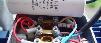
What is a capacitor
This part contains two metal plates, between which there is a dielectric layer. When voltage is applied to the plates, a charge accumulates on them. The electrical is inside the capacitor. The stronger the charge is on the plates, the stronger it is.
If you disconnect the voltage from the plates, the capacitor begins to release charge. If alternating current is used, the polarity of the voltage will periodically change. In this case, the plates will alternately have a positive and a negative charge.
The capacitance of a capacitor is its most important characteristic. It characterizes how much energy he is able to pass through himself. It is measured in farads. Since we are talking about a very large quantity, prefixes are usually used to indicate how small a part is used. The most commonly used is microfarads (this unit is equal to 0.000001 farads).
Motor connection procedure Source kabel-house.ru
There is a voltage rating for each capacitor. With it, this part is able to work for a long time and reliably. The maximum operating time value, which is expressed in the number of hours, must be indicated.
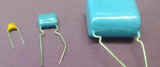
There are different types of capacitors:
- Polar are designed for use in DC circuits. An important feature is the need to connect in accordance with the polarity indicated on them. They are usually small in size and have a relatively large capacity.
- Non-polar ones can be connected regardless of polarity. They are used in alternating current circuits. They are larger in size than the polar ones.
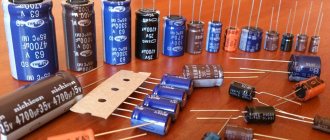
- Electrolytic. They use sheets of foil as plates, and the dielectric is a thin layer of oxide.
Electrolytic ones are best suited for use as a starting capacitor. They are often used with an AC frequency of 50 Hz and a voltage of 220-600 volts. Capacitors can have a fairly high capacity; it can be hundreds of thousands of microfarads.
These parts are highly vulnerable to overheating. If the thermal regime is violated, they quickly fail. Non-polar capacitors do not have this disadvantage, but are several times more expensive.
Single-phase asynchronous motor Source asutpp.ru
When connected in parallel, the containers add up. In the event that it is not enough, you can connect an additional part in parallel to increase it. In this situation there is no need to reassemble the trigger circuit.
Other types of capacitors are also used. For example, these can be vacuum, liquid, gas and others. However, they are not used as starting capacitors.
Sometimes the capacitor that is included in the design fails to start. In this case, it is recommended to remove it and replace it with one that has a larger capacity. For low-power motors, it is permissible for one capacitor to perform the functions of working and starting.
The use of polar capacitors in alternating voltage conditions is possible when the connection is made through a diode. Now the polarity of the contacts will not change. However, if the diode is faulty, the part will fail.
Construction of an asynchronous motor Source elektrikexpert.ru
Connecting a three-phase motor through a capacitor to a single-phase network
Everything here is quite simple and not simple. The fact is that at the moment of starting an asynchronous motor, a large starting current arises. Since the motor is an inductive element, and we achieve a certain current shift through a capacitor, that is, we achieve an optimal balance of inductive and capacitive current, then at the moment of starting, the inductive current prevails over the capacitive current due to its large magnitude and a circular magnetic field does not arise. And to start rotating the engine shaft, you need exactly a circular field, or at least almost circular. Therefore, capacitors are divided into starting and working.
Running capacitor for electric motor
The purpose of this capacitor is to maintain a circular magnetic field when the engine is already in operating mode. The capacitor must be designed to operate in alternating voltage. Such capacitors are usually called non-electrolytic. The capacitor voltage should be √2 times the mains voltage. The type of capacitor can be absolutely any. This applies to all AC voltage capacitors. We are accustomed to thinking that the voltage in the network is 220 volts, but this is the effective value (average), but the maximum (amplitude) is just √2 times greater or about 310 volts. A little later I will write an article on the effective and amplitude values and explain everything in more detail, but for now just believe me.
Starting capacitor for electric motor
The purpose of this capacitor is to provide a magnetic field when the engine is just starting. As I already said, at the moment of startup a very large inrush current arises (3-8 times the rated operating current), therefore, to create a circular magnetic field, a larger capacitor is required. Electrolytic can also be used as a starting one (these are capacitors that are used for constant voltage). And quite often they do this. In this case, it is recommended to connect electrolytic capacitors via a diode. This is due to the fact that electrolytic capacitors are cheaper. But it is better to use special capacitors marked “Motor starter” for this purpose. This way there will be less risk of damaging the capacitor, since although it is electrolytic, the series is designed specifically for starting AC motors.
Running and starting capacitor for electric motor
As a rule, one capacitor, which is used simultaneously as a working and starting capacitor, is installed on engines with a power of less than 1 kW. This is due to the fact that low-power motors do not have such a large starting current. In this case, the calculation is made based on the rated current. We'll touch on the calculations below. The operating and starting capacitor must be exclusively non-electrolytic and with an operating voltage of √2 times the mains voltage. When calculating such a capacitor, the rated value of the motor current is substituted into the formula.
Capacity size: working and starting
The specific capacity of these elements can be calculated using an online calculator on the Internet. The calculation is done independently using formulas.
For the trigger element
There are two known formulas for determining the capacity of a starting two-terminal network:
- for the “star” circuit – Cп = 2800*I/U;
- for the “triangle” circuit – Cп = 4800*I/U.
The rated current is calculated using the expression:
I = P/(1.73*U*η*cosϕ.
Here:
- P – motor power;
- U – network voltage;
- η – efficiency;
- cosϕ – power factor.
For work item
You can select a working capacitor based on the following calculation:
Cp = 1/2 Cp.
A running and stable engine requires the use of a working tank to rotate under load.
Connection without transformer
Under certain conditions, the load to the high-voltage network can be connected directly through a capacitor instead of the transformer used in this circuit design.
This type of power supply organization has its advantages and disadvantages. The first ones are as follows:
- With this method of limiting the mains voltage, the circuit of the converter device is significantly simplified.
- Its dimensions and weight are reduced, and its efficiency, on the contrary, increases.
- This power supply is convenient to use and easy to repair.
However, for all the listed advantages you have to pay with one, but very significant drawback regarding the safety of using this device.
Important! Unlike the transformer switching circuit, in which the dangerous potential of 220 Volts is separated from the output circuits by insulated coils, in this case there is a direct electrical connection.
And this is fraught with consequences in the form of electric shock to a user who accidentally touches the load circuit. This danger may arise in the event of an unexpected breakdown of the input capacitor with short circuit of the plates and a voltage of 220 Volts directly reaching the output of the device. Another no less unpleasant consequence of such a malfunction will be the burning of the load connected to the power supply (and this could be an expensive smartphone, for example).
Connection methods
In the most common case, the first capacitor is connected to the gap in one of the windings of an asynchronous electric motor, which is also often called “auxiliary”. The other is connected directly to the electrical network, and the third remains unused. This type of circuit is called “star”. There is also a triangle connection. It varies in connection method and complexity.
The second capacitive element, unlike the working one, is connected in parallel to the latter through a button or centrifugal switch. In the first case, control is carried out by a person, and in the second - by the drive itself. Both of these switches briefly close this circuit when the electric motor starts, and after it reaches operating mode, they open it.
Advantages of single-phase motor mechanism.
Among the advantages of 1-phase motors, the following are noted:
- simplicity of design;
- durability - with timely maintenance, the engine can last for years;
- reliability;
- efficiency – consumption of a small amount of energy;
- affordable price;
- maintainability - in case of failure, you can easily replace damaged or burnt parts;
- minimal care;
- possibility of operation from a network with a standard voltage of 220 V without energy converters.
Most modern household appliances are equipped with single-phase motors. The reason is explained by their simplicity and low cost. Such motors are used to equip large and small household appliances. In addition, they have found application in the creation of equipment for industrial and manufacturing enterprises.
But are there any disadvantages to a single-phase motor? There are not many of them. Almost all of them are due to the simplicity of the design. So:
- low power factor. For this reason, they are used to create most household appliances;
- high starting current;
- the ability to limit engine speed during network fluctuations.
The main disadvantage is the lack of starting torque. However, for household appliances and simple devices this minus is not significant and does not affect operation.
Online calculation of motor capacitor capacity
Enter data for calculating capacitors - motor power and efficiency
There is a special formula that can be used to calculate the required capacity accurately, but you can easily get by with an online calculator or recommendations that are derived from many experiments:
The working capacitor is taken at the rate of 0.8 μF per 1 kW of engine power; The launcher is selected 2-3 times more.
Capacitors must be non-polar, that is, not electrolytic. The operating voltage of these capacitors must be at least 1.5 times higher than the network voltage, that is, for a 220 V network we take capacitors with an operating voltage of 350 V and higher. To make starting easier, look for a special capacitor in the starting circuit. They have the words Start or Starting in their markings.
Starting capacitors for motors
These capacitors can be selected using the method from smallest to largest. Having thus selected the average capacity, you can gradually add and monitor the operating mode of the engine so that it does not overheat and has enough power on the shaft. Also, the starting capacitor is selected by adding until it starts smoothly without delays.
During normal operation of three-phase asynchronous electric motors with capacitor start, connected to a single-phase network, it is assumed that the capacitance of the capacitor will change (decrease) with increasing shaft speed. At the moment of starting asynchronous motors (especially with a load on the shaft) in a 220 V network, an increased capacity of the phase-shifting capacitor is required.
Using Electrolytic Capacitors
To start operation of a three-phase motor from 220V, the starting capacitor must have a large capacity. To move the shaft of an engine with a power of 3 kilowatts, 2100 uF of capacitance is needed. To select such a value of C, you will need a whole battery of non-polar components. Electrolytic two-terminal networks (electrolytes) have a larger capacity with smaller dimensions. But their inclusion in the alternating current circuit for a long time is unacceptable.
Carefully. When the container is connected for a long time, the electrolyte boils and the element explodes.
Generator repair kits
To eliminate these generator malfunctions, you will need to carry out repairs. When you start searching for a generator repair kit on the Internet, you should prepare for disappointment - the kits offered usually contain washers, bolts and nuts. And sometimes the generator can only be restored to functionality by replacing brushes, a diode bridge, a regulator... Therefore, the brave person who decides to repair it makes an individual repair kit from those parts that fit his generator. It looks something like this, as shown in the table below, using the example of a pair of generators for a VAZ 2110 and a Ford Focus 2.
| Generator KZATE 9402.3701-03 | ||
| Detail | Catalog number | Price, rub.) |
| Brushes | 1127014022 | 105 |
| Voltage regulator | 844.3702 | 580 |
| Diode bridge | BVO4-105-01 | 500 |
| Bearings | 6303 and 6203 | 345 |
| Generator Bosch 0 986 041 850 | ||
| Detail | Catalog number | Price, rub.) |
| Brushes | 140371 | 30 |
| Brush holder | 235607 | 245 |
| Voltage regulator | IN6601 | 1020 |
| Diode bridge | INR431 | 1400 |
| Bearings | 140084 and 140093 | 140/200 rubles |
Some general operating tips
When choosing a scheme, the user always has the opportunity to choose the scheme that specifically suits him. However, usually all the terminals of the required windings, the capacitor terminals for the electric motor, are brought out into the terminal box.
If you need to upgrade the system, or perhaps independently make the required calculation of the capacitor for your single-phase motor, then we can give you advice. You must proceed from the fact that for each kilowatt of power of your unit, a guaranteed specific capacity of 0.7 - 0.8 µF relative to the operating type or, accordingly, two and a half times greater capacity relative to the starting type.
When checking the technical condition of the engine, you may often notice that after quite a long period of operation, extraneous noise and unpleasant vibration have appeared. The rotor is difficult to check. The cause may be poor bearing condition. The treadmills were covered with terrible rust, scratches, and dents. Some balls and separator are damaged. In all these cases, you need to examine in detail and eliminate your existing faults. However, for minor damage, it is often sufficient to:
- carefully and thoroughly rinse the bearings with gasoline;
- then lubricate them;
- Clean your engine housing from dust and dirt.
Connection diagram "Star"
But if the engine has 6 outputs - terminals for connection, then you need to unwind it and see which terminals are interconnected. After that, it is reconnected to the same triangle.
To do this, change the jumpers, let's say there are 2 rows of terminals on the engine, 3 each, they are numbered from left to right (123.456), using wires they are connected in series 1 to 4, 2 to 5, 3 to 6, you first need to find the regulatory documents and look on which relay the winding starts and ends.
In this case, the conditional 456 will become: zero, working and phase - respectively. A capacitor is connected to them, as in the previous circuit.
When the capacitors are connected, all that remains is to test the assembled circuit, the main thing is not to get confused in the sequence of connecting the wires.
Necessary tools and components
Any installation of the above circuits will require minimal knowledge of electrical engineering, as well as skills in working with radio electronics and soldering small parts.
Tools you will need:
- A set of screwdrivers for assembling/disassembling the engine control unit. For older engines, it is better to select powerful flat-head screwdrivers made of good steel. Over a long period of engine operation, the bolts in the housing may “stick.” Unscrewing them will require a lot of effort and a good tool.
- Pliers for crimping wires and other manipulations.
- A sharp knife for stripping insulation.
- Soldering iron.
- Rosin and solder.
- Indicator screwdriver for searching for phases, as well as indicating a break in the cable.
- Multimeter. One of the main diagnostic devices.
You will also need radio components:
- Capacitors.
- Start button.
- Magnetic switch.
- Reverse toggle switch.
- Contact board.
The listed tools and radio components are enough to assemble the circuits presented above.
IMPORTANT: Do not connect the motor to the network without checking the operation of the assembled circuit. It can be tested using a multimeter. This will protect the equipment from short circuits.
What type of stepper motor do I have?
If you manually rotate the rotor of a switched off engine, you will notice that it does not move smoothly, but in steps. After you have spun the rotor, short-circuit all the motor wires and spin the rotor again. If the rotor spins the same way, then you have a jet engine. If it takes more effort to rotate the rotor, then you have a permanent magnet or hybrid motor. You can distinguish a permanent magnet motor from a hybrid motor by counting the number of steps in one revolution. To do this, it is not necessary to count all the steps, it is enough to roughly understand whether there are less than 50 or more. If it is less, it means you have a permanent magnet motor, and if it is more, it means you have a hybrid motor.
Start capacitor
So, let's start with the starting capacitor and, as the name itself suggests, such a capacitor is used only when the electric motor starts. After the running engine has reached the specified power and frequency, the starting capacitor is disconnected from operation.
Starting capacitors are used in certain types of motors and in the case when it is necessary to start the motor, on the shaft of which there is some load that prevents the free rotation of the shaft.
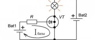
As can be seen from the diagram above, in order for the engine to start, we need to press the Kn1 button, which connects capacitor C1 for the time it takes for the engine to reach operating parameters.
After this, the capacitor is turned off and the motor continues to rotate due to the phase shift in the working windings. It is important to take into account that the operating voltage of capacitor C1 must be 1.15 times greater than the network voltage.
That is, for example, for a single-phase home network, the normal voltage is 230 Volts, which means the operating voltage of the capacitor must be at least 250 Volts.
Why do voltage sags occur?
Firstly, a standard car battery is not capable of delivering high currents quickly enough due to its high internal resistance (from 30 mOhm). As a result, instead of 13.5 - 14 V, even with the engine running, especially at moments of peak power, such as drum hits or other bass impulses, the voltage may drop by several volts. Such a voltage drop clearly leads to a significant decrease in power and the appearance of sound distortions, which can be heard even by an inexperienced listener.
Secondly, the significant distance of the battery from the amplifiers requires the use of rather long power cables. Any cable, even if it is made of copper and of the most suitable cross-section, has its own, albeit small, resistance. The longer the cable, the greater its resistance, the more it prevents the instantaneous transmission of large currents.
Thirdly, in the electrical circuit there are many connecting elements: fuse holders, power splitters, terminals, etc. Each of these elements connects different metals, creating the so-called transition resistance. Of course, high-quality brass connecting elements have little effect on overall voltage drops. However, as a rule, in pursuit of price, many use connecting elements made of low-quality zinc-based alloys. This leads to energy losses in these sections of the chain.
Capacitor is different from capacitor!
Radio amateurs use aluminum, tantalum, ceramic capacitors and many others. Its reliability during operation depends on the correct choice of the capacitor, since it must be used in operating modes that do not exceed the specified conditions. To do this, it is necessary to determine the values of the nominal parameters and their permissible changes during operation, possible modes and electrical loads, design, reliability and durability indicators, installation options, dimensions and weight.
Operating practice shows that the permitted voltage indicated on its body should not be less than on the electrical diagram. You can choose 20-30% more. The capacity can be used within +-10%, but it is better to take it no less than on the electrical circuit.
If capacitors must be in the power supply circuit, shunting HF (high frequencies), then it is better to use ceramic ones. If they are to be installed in a frequency-setting stage, then it is better to take them with a small TKE (temperature coefficient of capacitance) so that there is no frequency drift. In all cases, capacitors should be used at lower loads and lighter modes (compared to the maximum permissible).
Design and purpose of capacitors
This element of the electrical circuit consists of two plates (plates). The plates are positioned relative to each other so that there is a gap between them. When a capacitor is connected to an electric current circuit, charges accumulate on the plates. Due to the physical gap between the plates, the device has low conductivity.
Attention! This gap can be air or filled with a dielectric. The following dielectrics are used: paper, electrolyte, oxide films.
The main feature of such a two-terminal network is the ability to accumulate electric field energy and instantly transfer it to the load (charge and discharge).
Part device
The first prototype of the container was the Leyden jar, created in 1745 in the city of Leiden by the German von Kleist. The jar was lined with copper foil inside and out. This is how the idea of creating covers came about.
Leyden jars connected in parallel
The graphic designation of a two-terminal network on diagrams and drawings is two vertically located lines (like plates) with a gap between them.
Designation on diagrams