Zero and phase in electrics - the purpose of the phase and neutral wires
The owner of an apartment or private house who decides to carry out any procedure related to electricity, be it installing a socket or switch, hanging a chandelier or wall lamp, is invariably faced with the need to determine where the phase and neutral wires are located at the place of work, as well as the grounding cable. This is necessary in order to correctly connect the mounted element, as well as to avoid accidental electric shock. If you have some experience working with electricity, then this question will not confuse you, but for a beginner it can be a serious problem. In this article we will understand what phase and zero are in electrics, and we will tell you how to find these cables in a circuit, distinguishing them from each other.
Neutral connection rules
Chapter 1.7 PUE examines in detail electrical safety when grounding. The Electrician's Bible says:
- for electrical installations with voltages over 1 kV, a solidly grounded neutral is required, which discharges large fault currents into the ground;
- for equipment up to 1 V, an isolated or solid neutral can be used;
- the solidly grounded neutral must be grounded and connected to the grounding line through a transformer;
- grounding and neutral are carried out using copper (cross-section 4 mm2), aluminum (cross-section 6 mm2), insulated (1.5 mm2 and 2.5 mm2) cables;
- copper cables connected in one twist must have a cross-section of 1 mm2, aluminum cables - 2.5 mm2;
- if 3 wires are pulled from the panel of an apartment or floor, a protective neutral is used;
- if the group network is carried out using two cables, the protection neutral is extended from the nearest switchboard;
- All household appliances are added to zero - kettle, air conditioner, computer, washing machine, boiler, refrigerator.
Provided the connection diagram is correct, the protective neutral wire can prevent destruction of the electrical network and injury in cases of short circuit. The neutral evenly distributes the load across all lines, floors and apartments of a high-rise building. When connecting it for the first time and reconnecting it, you should be guided by the PUE.
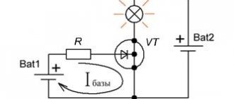
The role of the neutral wire - section Philosophy, Calculation of alternating current circuits with series connection of elements A) The neutral wire is necessary so that the Voltage in the Load Phases Remains Od.
The principle of operation of the neutral conductor
If we consider new buildings and old-type apartment buildings, then the transmission of electricity and its principles will differ significantly. Networks of new houses are developed according to the TN-S type:
- the electric current passes from a transformer or generator with a secondary winding, which is connected as a star, when all the wires converge at one zero point;
- the other ends of the wires are allocated to three terminals, which are also connected to the zero point and connected along the ground loop to the substation;
- a wire with a high-voltage characteristic, if it has zero resistance, is divided into working N (blue) and protective PE (yellow-green).
If we talk about old houses, they use the TN-C system:
- the grounded zero is located in a special distribution box;
- phase and neutral from the generator or transformer are laid to the house via underground or overhead high-voltage lines;
- the cables are connected in the input panel, which forms three phases with a voltage of 220 V or 380 V;
- From the panel, wiring is routed to apartments and entrances;
- the end consumer receives electricity from the conductor;
- the load is removed by applying a zero (N).
Grounding system TN-S
Marking of neutral wires
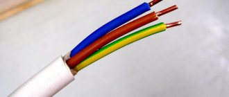
In order to make the neutral wire easily distinguishable from the rest, according to GOST, it is customary to use white-blue or simply blue cables for them.
When combining the neutral wire with grounding, striped yellow-green cables with the ends of the wires marked in blue are used:
Figure 2. Marking of the neutral wire
Need advice on your academic work? Ask a question to the teacher and get an answer in 15 minutes! Ask a Question
Features of the neutral wire
The neutral wire prevents undesirable situations during emergency operation.
Without it, in the event of a phase short circuit of two phases, the voltage in the third phase will instantly increase by √3 times. This will have a detrimental effect on the equipment that powers this source. If there is a zero in this situation, the voltage will not change. If one of the phases in a three-phase three-wire system (without zero) breaks, the voltage on the two remaining phases will decrease. They will be connected in series, and with this type of connection the voltage is distributed among consumers depending on their resistance.
If one of the phases in a three-phase four-wire system breaks , the voltage in the two remaining phases will not change its value.
Fuses are not installed in the neutral wire due to its great importance, because its breakage is undesirable
Since most of the time electrical installations operate, the current in this wire is either zero or insignificant, there is no point in making it the same cross-section as the phase wire cross-section. Most often, for reasons of economy, it has a smaller cross-section of the conductor than the cross-section of the conductors of the phases in one electrical installation. If the protective wire is not combined with the neutral wire, its cross-section is half that of the phase wire.
The role of the neutral wire during uneven load
If the load on each phase is different, then it is necessary to connect the neutral wire.
In the event of its break or sudden increase in resistance on it, the voltage will be distributed according to the power consumption to each of the loads of the three-phase circuit and, accordingly, the less power consumed, the greater the phase voltage the current consumer will receive.
This is unacceptable for many electrical appliances and can cause their malfunction and even a fire; it is to avoid such troubles that a neutral wire is connected to each socket.
Rules for connecting the neutral wire and grounding
Knowing the possible connection diagrams for grounding and the neutral wire, we can talk about the rules and requirements for their connection. After all, although they are not significant, they differ. In addition, we hope that we will explain the frequently asked question of why the neutral wire should be grounded.
- First of all, let's talk about the TT system. According to clause 1.7.59 of the PUE, this system can only be used in exceptional cases when none of the TN systems can provide the required level of protection.
Note! When using the TT system, the use of RCDs is mandatory. Moreover, the PUE standards impose separate requirements on them in terms of operating current.
- But for the TN system everything is not so simple. According to clause 1.7.61 of the PUE, at the entrance to the building or electrical installation, they must be re-grounded. Let's figure out why this is necessary.
- In the TN system, as we already know, the neutral and protective conductors are mounted with one wire. If this joint wire breaks, it turns out that the neutral and protective wires form a single whole. After all, they are not connected to the ground.
- If we do not have a connection to the ground, then, as we already know, when you turn on any electrical appliance or even a light bulb, the neutral wire ends up under phase voltage.
- But for a TN system, the neutral and phase wires are partially or completely combined. That is, the grounding wire is also under phase voltage. And our phase wire is connected to the body of our washing machine, hair dryer, refrigerator and other electrical equipment. It turns out that phase voltage will appear on their body. And if you touch them, you will receive an electric shock.
- It is precisely on the basis of these considerations that re-grounding the neutral wire according to the PUE for TN systems is mandatory. After all, such re-grounding reduces the risk of such cases. And if this is done for all electrical consumers, then the likelihood of such cases becomes even lower.
- In addition, the PUE standards in multi-storey buildings require connecting the PEN bus to the potential equalization bus, which, according to clause 1.7.82 of the PUE, must be connected to all grounded conductors in the house.
- The PUE imposes separate requirements on consumers who are connected to the electrical network using an overhead line. The neutral wire and grounding re-grounding circuit for such consumers must be equipped in accordance with clauses 17.101 and 1.7.102 of the PUE.
- For such consumers, not only the resistance of the artificial grounding conductor is standardized, but also requirements are imposed on its material, as well as its cross-section and thickness. Indeed, on overhead lines, a break in one wire is much more likely.
Types and modes of operation of the neutral wire - what is it
To equalize the voltage across the phases of electrical installations, a neutral wire is used. It is necessary to prevent ignition of devices and fires. The cable is part of the neutral - the common point of the generator or transformer winding, connected like a star. There are two types of conductor - working N and protective PE.
- What is a neutral wire
- Principle of operation
- What is the danger of damaging the neutral wire?
- Reaction of electrical appliances to zero loss
- Tasks and purpose of the neutral wire
- Re-grounding
- What is grounding and neutral wire
- Neutral connection rules
Why do you need color coding?
The phase and neutral in the operating circuit are determined by an indicator or a multimeter, but these devices are not always nearby. If the electrical circuit is made in accordance with existing standards, then the color of the core insulation can be used to determine their purpose without additional equipment.
This allows you to quickly find the right wire, so the electrician's work efficiency will be much higher.
The letter markings on the conductors are similar to the inscriptions on the terminals and contacts of electrical equipment. It is enough to insert and fix the desired wire into the terminal that corresponds to its marking. To be on the safe side, it is better to additionally check with a tester where the phase is located.
What is important to know and remember
Current always flows along the line of least resistance. Therefore, it is strictly forbidden to take or touch the wires with your left and right hands (then the work of the heart will be paralyzed, which will lead to almost instant death). Likewise, it is prohibited to work with bare hands, in uninsulated or wet shoes, and so on. And you should never hold the wire in your hand! As soon as the current flows through the muscles of the hand, they will sharply contract, the hand will clench into a fist, and you simply will not be able to release this wire, which will most likely lead to injury or even death.
And, of course, use tools with high-quality, serviceable insulation on the handles.
What is the phase characterized by?
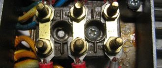
A phase is a live wire. This conductor is located relative to another, called zero. The rationale for determining the phase is the peculiarity of the substation design. The alternating current generated by them has the same frequency of 50 Hz. At the same time, the emfs are shifted relative to each other in time by a certain phase angle.
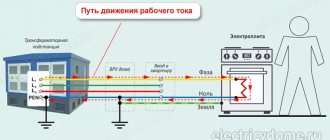
The first figure schematically shows the power supply system of a standard residential property with three phases and one neutral conductor. The second image demonstrates the features of connecting electricity to the apartment from a transformer. The consumer in the form of an electrical appliance is designated as Rн. In this case, two wires come out of the transformer in the form of a phase and a zero, to which the ZML grounding is connected. The third figure shows how clearly the installation of power supply is carried out in the absence of a neutral grounded wire connected to the apartment. Grounding in this situation is located directly in the living space.
The concept of phase follows from the definition of electricity. The nature of the formation and flow of alternating current allows us to understand the nature and purpose of the phase wire. Alternating current differs from direct current in value and direction; it can be observed in sockets and direct connections to electrical panels. Main characteristics of alternating current:
- voltage;
- frequency.
Single-phase current is an alternating current obtained through the rotational movement of a conductor or system of conductors under magnetic flux conditions. The wires can be combined in one coil. In order to transmit electricity, two wires are used, including phase and neutral. The voltage between the conductors is 220 Volts. There are two ways to connect single-phase current to a consumer:
- two-wire;
- three-wire.
In the first case, two conductors are used, one of which carries phase current, and the second is zero. This is an outdated power supply scheme that was used during the Soviet era. The second method involves the presence of one more wire, which is necessary for grounding, which helps prevent electric shock to a person, drain electrical leaks and prevent damage to electrical appliances.
Two-phase current is called the fusion of two phases that are shifted relative to each other. The shift angle can be 90 degrees. For example, you can take two coils with perpendicular axes, which are connected to a two-phase current. As a result, a system of two magnetic fields is formed. The resulting magnetic field will have a vector that rotates at the same angle and at a constant speed, creating a magnetic field.
What does a break in the neutral wire lead to, what types of break are there?
If the neutral conductor acts as protection, why is its break dangerous? To answer this question, consider the situation of a break in three-phase and single-phase networks.
Zero break in a three-phase network
A three-phase network is built in such a way that the electric current flows through the working conductor to the consumer and goes to neutral. The voltage in a normal situation between them is 220 V. In the case when the zero is disconnected, the consumers will be connected according to the “star without neutral line” circuit. This means that each consumer will not receive a stable phase voltage of 220 V, but a “walking” linear voltage from 0 to 380 V. This occurs due to phase imbalance, i.e. uneven load on different phases.
As an example, let's take three apartments that are connected to different phases. Residents of the first apartment are at home and use a washing machine, electric oven and other electrical appliances. No one lives in the second apartment, so all appliances are unplugged. In the third, everyone went to work, leaving some equipment on standby. In the event of a zero break, the equipment in apartment No. 1 will stop working or will malfunction, because the voltage will drop to 50.100 V, and in apartment No. 3 the connected devices will receive 300.350 V and will fail, causing a fire. Apartment No. 2 will not be damaged, because all equipment is turned off.
This happens because when the neutral breaks (in a situation with a large total resistance), a greater voltage is obtained, which provokes equipment failure.
Zero break in a single-phase network
In a single-phase network, a broken neutral is dangerous for humans. This can be explained by the fact that a dangerous potential appears in the outlet where there was zero. This situation is especially dangerous in systems with TN-C grounding, because a combined neutral and grounding conductor PEN is used. Therefore, when a wire breaks, a potential dangerous to human life appears on the open, uninsulated parts of the casing of electrical appliances.
What is grounding and neutral wire
The neutral conductor also balances the potentials in several phases. According to the PUE, the task of the neutral is to provide current to consumers. It must be connected to a solidly grounded neutral point of the transformer. In private houses and apartments where single-phase electrical networks are used, there must be two cables for the equipment to operate: phase and neutral. “Zero” is connected to “ground”, and the potential on it should be equal to 0. It is connected to “ground” using a ground loop. Accordingly, there should be no voltage. If communication with it is disrupted during operation of the equipment, it will be under the same voltage as in the phase, respectively - 220. On modern diagrams it is designated by the letter N, and in Soviet documents, already outdated, the number 0 was used. According to the PUE, the cable must cover with blue insulation.
The grounding conductor, according to the PUE, is needed for safety purposes. Under normal conditions, there is no voltage on it, and it works as a conductor only if the insulation of the conducting phase or neutral is damaged. Accordingly, grounding is necessary so that in the event of a breakdown no additional problems arise. For example, when your refrigerator’s protection is broken, and the refrigerator itself is not grounded, touching it will be equivalent to touching the 220 V phase. But if the refrigerator is grounded, it will not give an electric shock, since the potential will go into the ground.
The protective conductor is designated by the letters “PE”. According to the rule, its insulation must be painted in yellow and green stripes. If the diagram has the designation “PEN”, it means that the neutral and protective wires are combined into one. Such a cable should be painted blue with yellow and green stripes at the ends.
To equalize different voltages, all ends of the phase windings are connected into a node, which is called a neutral point, for which a neutral wire is used when connected in a “star”. The star circuit with neutral is used in practice, because in it, at any load, there is no phase imbalance in voltage, i.e. all phase voltages are equal.
If you take into account all of the above, then you probably understand the critical importance of a neutral cable that equalizes voltage in several phases, because its absence threatens with serious problems - from damage and loss of equipment to fires and even the risk of fatal electric shock to a person.
Neutral protective conductor, apartment grounding system
In this article we will talk about grounding in an apartment, namely, what an apartment grounding system and a neutral protective conductor are. Let's consider the grounding systems TN-C, TN-S, TN-CS.
How is the neutral protective conductor designated?
The apartment is powered by alternating current with a voltage rating of 220-230 Volts.
- In this case, one working conductor is phase (or simply “Phase”), and the second working conductor is zero (otherwise “working zero”). In the diagrams, “Phase” is denoted by -L, “Zero” is denoted by -N. This type of wiring is called two-wire.
- In addition to the two-wire electrical wiring of the apartment, a three-wire one is used. The third wire is the neutral protective wire (or "Ground"), designated -PE. The color of the grounding conductor in the cable is yellow-green.
In the diagram and devices, the neutral protective conductor (EARTH) is designated as follows.
Purpose of the neutral protective conductor
The neutral protective conductor is designed to create a short-term short-circuit current and trigger a protective shutdown of a damaged electrical appliance from the supply network, in order to ensure your electrical safety.
Power system and grounding system
In residential buildings, power is supplied from electrical installations in which the neutral (Zero) of the power source is solidly grounded, and the open conductive parts of the electrical installation are connected to this solidly grounded neutral. This power supply system is designated TN.
The TN power supply system for your apartment can be one of three types.
1.TN-C grounding system
TN-C system is a TN system in which the neutral protective and neutral working conductors are combined in one conductor along the entire length of the line from the source to the apartment.
Apartment power supply system TN-C
Important! This power supply system is used in all old houses. Since 2007, according to the PUE (Electrical Installation Rules), the TN-C wiring diagram in newly built houses is prohibited.
In case of major renovation of an apartment, it is necessary to convert the apartment's TN wiring diagram to the TN-CS system (see below).
2.TN-S grounding system
The TN-S power supply system is a modified TN power supply system, in which the neutral protective and neutral working conductors are separated along the entire length of the line from the source to the apartment.
Apartment power supply system TN-S
Important! Do not confuse conductors PE (Earth) and N (zero) throughout the entire electrical wiring of the apartment.
3.TN-CS grounding system
The TN-CS power supply system is a modified TN power supply system, in which the functions of the neutral protective and neutral working conductors are combined in one conductor in some part of it, starting from the power source.
Apartment power supply system TN-CS
That is, in the apartment the conductors PE (Earth) and N (Zero) are separated, and in the floor panel they are combined and connected to one terminal (see diagram above).
This grounding scheme is especially relevant for serious renovation of an apartment with a TN-C power supply system and the transition of electrical wiring to a TN-CS power supply system.
Rules for installing a three-wire apartment power supply system
- The neutral protective conductor must not be interrupted by any fuses or circuit breakers.
- If there is an RCD (residual current device) in the shield, the neutral protective wire (Ground) should not have contact with the N conductor (Zero) anywhere on the power supply line.
Otherwise, the RCD (residual current device) will be triggered. - The neutral protective conductor in the apartment must have a cross-section equal to the cross-section of the working conductors.
- The neutral protective conductor must be laid in close proximity to the working conductors. In other words, in one cable.
- Laying the neutral protective conductor separately from the working wires is prohibited!
- General-purpose communications (heating pipes, water supply pipes, fittings in the walls) cannot be used for grounding the electrical wiring of an apartment.
- You cannot connect the neutral protective conductor to independent (“foreign”) grounding buses. If you have these on your landing.
- The insulation resistance must correspond to the table below:
According to PTEEP (Rules for the technical operation of consumer electrical installations), Appendix 3; 3.1 (part of table 37), minimum permissible values of insulation resistance of electrical installations with voltages up to 1000 V:
| ||
| Switchgears, boards and conductors | 1000-2500 | 1,0 |
| Electrical wiring, including lighting networks | 1000 | 0,5 |
| Stationary electric stoves | 1000 | 1,0 |
| Power cable lines | 2500 | 0,5 |
| Stator windings of synchronous electric motors | 1000 | 1,0 |
Especially for the site: Everything about apartment renovation