Why is the neutral conductor dangerous?
The neutral conductor, if connected correctly, has no voltage. It becomes dangerous only if it is broken or damaged. The wire can be damaged as a result of a short circuit, mechanical stress, as well as due to the operating life of the installation. As a result:
- the conductor burns out in the distribution panel, and its voltage increases to 380 V;
- if a break occurs in the house, then only one phase remains, which does not power anything;
- devices may begin to shock, break down and burn out.
You may be interested in Description of wire clamps
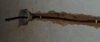
Burnt neutral conductor
Thus, the role of the neutral conductor is extremely important. Not only the correct operation of electrical equipment, but also human health depends on the correctness of its installation and installation.
What is a neutral conductor
The neutral wire, or neutral wire, is a conductor that is designed to power various electrical appliances and is connected to the solidly grounded neutral of the transformer. Putting aside technical terms and speaking in simple terms, this is the conductor connected to that part of the transformer or power generator that is grounded.
Working and protective neutral wires
If we take into account the single-phase electrical network used in almost all private houses and apartments, then for the functioning of electrical appliances, phase and neutral wires are required. The neutral cable is simply connected to ground and should ideally be at zero potential, meaning no voltage at all.
Important! There will be no voltage at zero only if it is connected to ground. If the connection was disrupted by a person or other external factors, then during the operation of a particular device, the phase voltage of a single-phase network (220 V) will be supplied to it.
Diagrams and drawings designate the neutral conductor with the Latin letter “N”, but in old Soviet diagrams and textbooks it was customary to sign it with the number “0”. Physically, the wire insulation must be blue. This is clearly reflected in clause 1.1.30 of the Electrical Installation Rules.
According to the PUE, the insulation of the neutral working conductor should be blue
The principle of operation of the neutral conductor
If we consider new buildings and old-type apartment buildings, then the transmission of electricity and its principles will differ significantly. Networks of new houses are developed according to the TN-S type:
- the electric current passes from a transformer or generator with a secondary winding, which is connected as a star, when all the wires converge at one zero point;
- the other ends of the wires are allocated to three terminals, which are also connected to the zero point and connected along the ground loop to the substation;
- a wire with a high-voltage characteristic, if it has zero resistance, is divided into working N (blue) and protective PE (yellow-green).
You might be interested in Connecting copper and aluminum
If we talk about old houses, they use the TN-C system:
- the grounded zero is located in a special distribution box;
- phase and neutral from the generator or transformer are laid to the house via underground or overhead high-voltage lines;
- the cables are connected in the input panel, which forms three phases with a voltage of 220 V or 380 V;
- From the panel, wiring is routed to apartments and entrances;
- the end consumer receives electricity from the conductor;
- the load is removed by applying a zero (N).
Grounding system TN-S
Why can the current in the zero (neutral) wire exceed the current in the phase wire?
In a three-phase system, with a symmetrical linear load (for example, a three-phase electric motor), there is no current in the neutral wire.
In reality, ideal symmetry does not exist; there will be a current in the neutral wire, but it will be less than the phase wires (if you completely disconnect the load from two phases, it will become equal to the current of the remaining phase). Since the current in the neutral wire was less than the current in the phase conductor (previously there were few nonlinear loads), to save money, the neutral conductor was made thinner than the phase conductors; now the cross-section of the neutral conductor coincides with the cross-section of the phase conductor. If the main energy consumption comes from nonlinear loads (switching power supplies without PFC, fluorescent lamps with electronic ballasts without PFC, etc. - current is consumed in narrow pulses near the peak of the supply voltage), there are recommendations for doubling the cross-section of the neutral conductor (relative to the cross-section , calculated for phase conductors). This is due to the fact that a significant amount of current harmonics divisible by three will also flow in the neutral wire (the third will be especially strong - 150 Hz).
Since only phase leads are protected from overcurrent, overloading the zero (neutral) wire can lead to its damage, “zero burnout” - which can lead to a significant imbalance in phase voltages and damage to consumers. It turns out that powerful consumers with a non-sinusoidal input current (non-linear loads) can not only cause distortion of the network voltage waveform and “contaminate” the network with interference, but also lead to an emergency situation, disabling the cable and other consumers.
Examples of nonlinear loads that can cause an increase in current in the neutral conductor (if they do not have a power factor corrector): Gas discharge lamps LED lamps Arc and induction furnaces Transformers operating in saturation mode Computers, monitors, office equipment Televisions Inverter air conditioners Uninterruptible power supplies Microwave ovens Switching power supplies , inverters, frequency converters Electric motors with speed controllers (inverters)
The shape of the current consumed by a non-linear load is significantly different from (not at all similar to) a pure sine wave. Mathematically, the shape of a non-sinusoidal current can be represented as a sum of decreasing amplitude sinusoids that are multiples of the supply voltage frequency (50 Hz, 100 Hz, 150 Hz, 200 Hz...).
GOST 30804.4.30-2013 prescribes taking into account harmonics of at least the 40th order. But only harmonics that are multiples of the third (the rest are mutually compensated by adding up) are summed up in the neutral conductor and cause a very significant current, to which is also added the current caused by the asymmetry of the supply voltage, its non-sinusoidality and load asymmetry. The main contribution is made by the third harmonic (current flows in the neutral with a frequency of 150 Hz) - other harmonics are small.
GOST R 50571.5.52-2011: suggests finding out the current in the neutral conductor and selecting the cross-section of all conductors along the most loaded wire; It should be pointed out that the situation worsens if only two phases are loaded in a three-phase system. In this case, the current of higher harmonics in the neutral conductor will be summed up by the imbalance current; if the third harmonic fraction exceeds 33%, it is necessary to increase the cross-sectional area of the neutral conductor.
Source
