Selection of connecting wires
Installing audio leads is different from normal electrical connections.
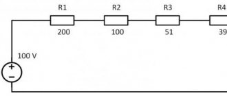
The fact is that an alternating sound signal propagates through the conductors going to the speakers and speakers. It has a frequency ranging from 20 Hertz to 20 kilohertz. In principle, the frequency is low, but linear distortions, electromagnetic interference, and interference are possible. They degrade the sound quality. Therefore, along with observing the rules for choosing the cross-sectional area of the wire, the type of conductor is selected. The cross-section is usually chosen from the following consideration: for every 10 watts of amplifier power - approximately 1 sq. mm of wire cross-sectional area. That is, with a radio power of 40 watts per channel, the cross-section of the conductor leading to the speaker must be at least 4 sq. mm.
You should think about choosing the type of speaker cable if the radio is capable of providing high-quality sound. On the Hi-end equipment market you can find many different speaker cables with unique parameters and prices.
The feasibility of installing such expensive conductors for a middle-class car radio is zero. The main thing when connecting is to ensure that the phases of the speakers and speakers are synchronized. Otherwise, the interior will be filled with cacophony instead of high-quality sound.
Tip 1. Check the contact of the terminals with the battery
The car may not start due to poor contact between the terminals and the battery. This can happen not only in severe frost, but also in any other weather. In any case, it is better to check the connections first. To do this, open the hood of the car and using wrenches (usually a 10-size open-end wrench is suitable) alternately tighten both battery terminals to the limit. If these manipulations were enough for the car to start, luck is on your side! But if the car still does not start when you turn the ignition key, then your battery is really dead.
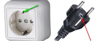
Ground wire color coding
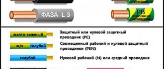
The rules indicate what color the ground wire in electrical installations is. This is a yellow-green wire, the color of which stands out well against the background of the other wires. It is acceptable to use a wire with yellow insulation and a green stripe on it, or it can be green insulation with a yellow stripe. It is not allowed to use any other color of the ground wire, just as it is not allowed to use green-yellow conductors for installing circuits on which voltage is present or may be applied.
The listed labeling rules are observed in the countries of the post-Soviet space and in the countries of the European Union. Other states mark the cores in a different way, which can be seen on imported equipment.
Basic colors for marking abroad:
- neutral – white, gray or black;
- protective grounding – yellow or green.
Standards in a number of countries allow the use of bare metal without insulation as protective grounding.
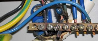
Grounding wires are switched on prefabricated non-insulated terminals and connect to each other all metal parts of the structure that do not have reliable electrical contact with each other.
Wire colors in electrical wiring
The color identification scheme is convenient not only for installation. As a rule, different contractors install and operate electrical wiring. Compliance with standards prevents errors during repair work and in the modernization process.
Something to remember! Domestic standards have changed several times over the past decades. Currently, the markings discussed above are used.
Color of zero working and zero protective wires
The color options for the shells will help you recognize the intended purpose of the conductors:
- blue – working zero;
- transverse or longitudinal combinations of yellow and green stripes - protective zero;
- main blue with a change to a combination of yellow and green stripes at the junctions - combined working and protective zero.
Colors for 220V and 380V networks
Installation of single- and three-phase electrical networks is facilitated if the wiring is made with multi-color wire. Previously, a flat two-core white wire was used for single-phase residential wiring. During installation and repair, to eliminate errors, it was necessary to ring each core individually.
The production of cable products with colored cores in different colors reduces the labor intensity of the work. To indicate phase and zero in single-phase wiring, it is customary to use the following colors:
- red, brown or black – phase wire;
- other colors (preferably blue) – neutral wire.
The phase markings in a three-phase network are slightly different:
- red (brown) – 1 phase;
- black – 2 phase;
- gray (white) – 3 phase;
- blue (cyan) – working zero (neutral)
- yellow-green – grounding.
Domestic cable products comply with the standard for core coloring, so a multiphase cable contains differently colored cores, where the phase is white, red and black, the neutral is blue, and the ground is yellow-green conductors.
When servicing networks installed according to modern standards, it is possible to accurately determine the purpose of the wires in the junction boxes. If there is a bundle of multi-colored wires, the brown one will definitely be phase. The neutral wire in distribution boxes has no branches or breaks. The exception is branches to multi-pole switching devices with complete circuit breaking.
Coloring in DC networks
For DC networks, it is customary to mark conductors connected to the positive pole in red, and to the negative pole in black or blue. In bipolar circuits, blue insulation is used to mark the midpoint (zero) of the power supply.
There are no standards for color codes on multi-voltage circuits. What color are the plus and minus wires, what voltage is in them - this can only be determined by the decoding of the device manufacturer, which is often given in the documentation or on one of the walls of the structure.
Automotive wiring is characterized by the fact that in it the circuits with positive voltage of the on-board network are red or its shades (pink, orange), and those connected to ground are black. The remaining wires have a specific color, which is determined by the car manufacturer.
Distinguishing wires by insulation color in multi-core cables
Cables with a large number are used for laying AC networks. In these situations, it is possible to use different shades of the insulating layer. The color of the phase-zero-ground wires is important if the wiring is installed and serviced by different specialists. This allows you to get started right away.
Different shades of insulation save timeSource domamaster.net
The colors of the wires in the 220 electrics with 3 cores must accurately indicate the phase, working zero and protective ground. There are state standards that allow the use of nine color options to indicate phase and two for neutral and ground.
If a five-wire conductor is used, then the colors according to the requirements are used to mark the zero and ground, and the remaining colors are used for the phase, one of which is usually brown.
Standard colors are used for grounding and neutral, and all others are used to indicate phase. Source magnetic.uz
How to check the correctness of marking and wiring
Wire colors in electrical engineering are designed to speed up the identification of conductors, but relying only on colors is dangerous - they could be connected incorrectly. Therefore, before starting work, you should make sure that you have correctly identified their affiliation.
Take a multimeter and/or an indicator screwdriver. It’s easy to work with a screwdriver: when you touch a phase, the LED built into the housing lights up. So it will be easy to identify phase conductors. If the cable is two-wire, there are no problems - the second conductor is zero. But if the wire is three-wire, you will need a multimeter or tester - with their help we will determine which of the remaining two is phase and which is zero.
We set the switch on the device so that the selected jackal is more than 220 V. Then we take two probes, hold them by the plastic handles, carefully touch the metal rod of one probe to the found phase wire, the second to the supposed zero. The screen should display 220 V or the current voltage. In fact, it may be significantly lower - this is our reality.
If 220 V or a little more is displayed, this is zero, and the other wire is presumably “ground”. If the value is less, we continue checking. With one probe we again touch the phase, with the second - to the intended grounding. If the instrument readings are lower than during the first measurement, there is “ground” in front of you and it should be green. If the readings turn out to be higher, it means that somewhere there was a mistake with “zero” in front of you. In such a situation, there are two options: look for exactly where the wires were connected incorrectly (preferable) or simply move on, remembering or noting the existing position.
And, in conclusion, let me give you some advice: when laying wiring and connecting wires, always connect conductors of the same color, do not confuse them. This can lead to disastrous results - at best, equipment failure, but there may also be injuries and fires.
Modern installation of electrical wiring cannot be imagined without the use of wires in insulation of different colors. Color marking is not done for beauty; it is urgently needed in the electrification of objects. Color marking not only indicates the purpose of each individual wire in the overall bundle for ease of connection, but also reduces the risk of errors when installing wires. Allows you to prevent the possibility of short circuits during test startup or electric shock during service and repair work on the network.
A certain choice of color marking is not accidental, but corresponds to the main standard - PUE. They are required to identify wire cores by color or alphanumeric characters.
Color coding of electrical wires
Installation of lighting networks and distribution of power to sockets is carried out using a cable with three conductors.
Multi-colored markings are applied along the entire length of the conductor. It is also permissible to identify the ends of the cores and switching points using multi-colored heat-shrinkable tubing (cambrics) or colored electrical tape.
We propose to consider how color marking of conductors is carried out in electrical networks of single-phase, three-phase and direct current.
The grounding conductor must be marked yellow-green. In distribution panels (DP), the “ground” must be connected to the grounding bus, to the housing or metal door of the switchboard. In distribution boxes, the connection is made to the grounding wires of the lamps and to the grounding contacts in the sockets. There is no need to connect the “ground” conductor to the residual current device, therefore it is recommended to install the RCD only in those residential premises where the “old-fashioned” electrical wiring is made with two conductors.
Grounding conductor
How to correctly determine the polarity on wires in a car
If the voltage on the car is checked, the course is set to search for a constant one. 20W is the correct setting if you are testing the battery. Therefore, you need to adjust the dial to the desired range/setting and connect the probes to whatever component you want to get a reading for.
You might be interested in Calculating cross-sectional area
How to check a headlight with a multimeter
Multimeter
To check the headlight wiring, you need to find the ground wire. There are 2-4 wires coming from the connector that connects to the light bulb. Where there are two or three wires, only one of them is ground, while four-wire connectors will have two grounds.
To test the wires on the headlight, you need to set the multimeter to resistance. You can place one of the probes on the ground and the other on the negative pole of the car battery.
Note! If continuity is not read, then there is a problem with the ground wire, meaning it needs to be replaced.
How to Test a Car's Ground Wire Using a Multimeter
To test ground wires, start by measuring resistance. Test along the wiring to check the reading is 5 ohms or less. If it exceeds, you will need to check the wire further. You need to switch the multimeter to constant voltage and turn on any electrical part that is having problems. It's worth double-checking the wire to make sure the reading doesn't exceed 0.05V. If it does, you'll need to use a different ground location or use a tie strap.
How to Check if a Fuse Has Blown Using a Multimeter
Troubleshooting a fuse using a multimeter is extremely easy. You need to set the multimeter to the lowest ohm setting and place the probes on both sides of the fuse covers. Fuses do not have polarity, so the contacts used will not show values.
Circuit breakers
Note! If the resistance value is very low, then the fuse is working perfectly. If the resistance value does not change after connecting the contacts, the fuse has blown.
You can also test the fuse using a test light. You need to turn on the key and touch both sides of the fuse with the tip of the test light. If it lights up, the fuse is good. If it does not light up, the fuse needs to be replaced.
How to use a multimeter from a car battery
If you're having trouble starting your car, one of the most common reasons is a weak battery. This is something that can be easily checked using a multimeter, which will also give an accurate idea of how much charge the battery actually has left. Testing your car battery first is a great way to rule out a likely cult for many electrical problems.
When testing a car battery, you need to check the voltage by setting the multimeter to 20 V DC. It is necessary to connect contacts to both terminals of the battery that match the color. It is better to turn on the headlights to get accurate information regarding the charge.
Important! The headlights must be turned on when the engine is stalled.
In most cases the reading will be somewhere between 11.8 V and 12.6 V. The higher the voltage reading, the more charge there is in the battery. A reading of 12.5V means the battery is almost fully charged, while a reading of 11.9V means the battery should be replaced soon.
You may be interested in Features of alternating current
Checking the charger
Electronic devices use adapters to convert alternating current supplied from wall outlets to direct current. Once converted to direct current, current flows in one direction, hence the term direct current.
What color is the positive wire on the charger?
Note! One wire is positive, which conducts current to the device, and the other is negative, which completes the circuit. The direction of flow is called polarity and is marked on chargers using a diagram. If there is no diagram on the charger, it is worth checking the polarity.
The color polarity of the charger wires does not matter.
To determine if the charger is fit for use, do the following:
- Connect the charger to a power outlet.
- Turn on the multimeter and set the settings to DC voltage. Most multimeters indicate this setting as VDC.
- Insert the red positive contact into the hole in the charger tip.
- Touch the black negative terminal and the outer metal part of the charger tip.
- Monitor the multimeter readings. You may see a positive or negative number indicating the DC output voltage of the charger. If the number is positive, then the polarity on the inside of the charger tip is positive. If the number is negative, then the polarity inside is negative.
Wire Classification Options
Before you understand the decoding of the markings, it is recommended that you familiarize yourself with the parameters by which the wires are divided:
- Number of cores Depending on this parameter, the cable can be used to ensure the operation of electric motors, for wiring in a house or apartment, for transmitting current in power networks.
- Current-carrying conductor material. The materials most often used in electrical applications are copper and aluminum or a combination of these metals.
- Insulation. Wires can be with or without insulation. Bare conductors provide communication for power lines. Insulated ones are laid in places where there is a possibility of exposure to external factors such as wind, water, dust or snow. Plastic, rubber, lead, paper and many other materials are used as insulation.
- Cable section. Using this indicator, you can determine the strength of alternating or direct current that will pass through the conductors.
- Other indicators. Resistance, power and voltage indicators are very important for network wiring and connecting various devices.
Knowing which conductors are responsible for the loads, you can correctly connect to the meter, repair the wiring, connect the oxygen sensor in the car, etc.
How to find plus and minus
When a technician deals with electrical wiring, identifying the negative and positive wires plays an important role. Some wires will be clearly marked with a plus (“+„) or minus (“-”) sign. For unlabeled wires, you can first try to check the polarity by looking at physical characteristics such as color or texture. If this method confuses you, you can check the wires with a digital multimeter.
You may be interested in Determining voltage drop
Some wires have plus and minus
Important details:
- Appliance plugs don't actually have positive and negative sides. Instead, they have one prong hot and the other neutral;
- Positive and negative wires have differences in shape and material. The ribbed one is usually the negative wire on the extension cord. If there is a wire in which both sides are the same color, usually copper with a knurled texture is negative. You need to run your fingers along the wire to determine which side has the ribs. If it is smooth, then it has a positive indicator.
- on speakers and amplifiers, the silver wire is usually negative and the copper wire is positive. They are often held together by a transparent case, so it is easy to determine the polarity of each side. Often the black wire is negative and the red wire is positive. If both cables are black and one has a white stripe, then it is negative, and the plain black is positive.
- You can look in your owner's manual to determine which wires are negative in your vehicle. Each car follows its own color coding system for wires. There is no standard or international system, so it is worth finding the wiring diagram that matches your make and model in your owner's manual.
Neutral wire designation
The working zero is sometimes called neutral. Cables for this purpose have all blue or cyan insulation options. On the diagrams, the neutral is signed with the letter of the Latin alphabet “N” and a blue line. This letter is also used to designate the contacts to which the zero should be connected.
When designating stranded conductors with high flexibility, lighter colors of insulation are used, then for rigid wires with one core, a darker shade of insulation is used.
Neutral wire blue and light blue have different numbers of wiresSource electric-in-home.com
Determination of polarity by alternative methods
If it happens that you don’t have a multimeter at hand, but you need to find the polarity, you can use alternative and “folk” means.
For example, speaker wiring charges are checked using a 3-volt battery. To do this, you need to briefly touch the wires connected to the battery to the speaker terminals.
If the cone in the speaker begins to move outward, this will mean that the positive terminal of the speaker is connected to the positive terminal of the battery, and the negative terminal to the negative terminal. If the diffuser moves inward, the polarity is reversed: the positive terminal is connected to the minus, and the negative terminal to the plus.
If you need to connect a DC power supply or battery, but there are no polarity markings on them, and you don’t have a multimeter at hand, plus and minus can be determined by “folk” methods using improvised materials.
The easiest way to determine polarity that you can use at home is to use potatoes. To do this, you need to take one raw potato tuber and cut it in half. After this, two wires (preferably of different colors or with any other distinctive sign) with their bare ends are stuck into a cut of potato at a distance of 1-2 centimeters from each other.
The other ends of the wires are connected to the constant current source being tested, and the device is turned on (if it is a battery, then after connecting the wires, nothing else needs to be done) for 15-20 minutes. After this time, a light green spot will form on the potato cut around one of the wires, which will be a sign of a positive charge on the wire.
Tip 5. “Light up” from another car
Take off your gloves, raise your right hand parallel to the ground and bend your thumb. Catch a passing car and beg the savior to give you a light. To properly and safely light one car from another you need to take three simple steps:
Remember: The black terminal of the battery is negative, the red terminal is positive.
- Using wires with cigarette lighter clips, first connect the positive terminal of the discharged battery and the same positive terminal of the charged one. Connect the second wire to the negative terminal of the charged battery and, attention. mass (metal part of the car engine). Do not connect the negative terminals to each other.
- First you need to start the car with a charged battery. Let it run at 2000 rpm for 20 minutes. This time will be enough for your frozen battery to be recharged from the donor to the level necessary to start the engine on its own.
- Start your car and, if the start is complete, let both cars work together for another 5-10 minutes. Disconnect the wires from the batteries in reverse order.
Before starting to drive, we recommend idling a little to increase the charge in the battery a little more.
Checking the correct connection
Unfortunately, not all electricians strictly follow the standards and make mistakes in choosing a conductor when making connections. Therefore, when hanging a chandelier, installing a socket or other electrical installation device, it is better to additionally check whether the insulation of each core corresponds to its purpose.
Mandatory checking of the neutral or phase is dictated by safety standards and the instinct of self-preservation: if you accidentally mix up the contacts during installation, you can get an unpleasant injury - an electrical burn
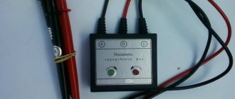
For identification, installers use two methods: the first is checking with an indicator screwdriver, the second is using a tester or multimeter. The phase is usually determined with a screwdriver, and neutral and zero are determined with measuring instruments.
How to use the indicator?
Even such simple devices as indicator screwdrivers are different. Some of them are equipped with a small button, others are triggered automatically when a metal rod and a current-carrying conductor or contact are connected.
But all models without exception have a built-in LED that lights up under voltage.
The indicator screwdriver is preferred by amateurs who do not have special qualifications. Professional electricians value accuracy, so they always have a tester with them.
A screwdriver is a convenient tool for identifying the phase conductor. To find out whether the wire is working, use the metal blade of a screwdriver to gently touch the exposed wire.
If the LED lights up, the wire is energized. The absence of a signal indicates that it is ground or zero.
When using the indicator, you must adhere to the safety rules. Even if the screwdriver handle is insulated, it is recommended to wear protective gloves (with a rubberized inner layer), as when working with electricians in general.
The verification procedure is performed with one hand, therefore, the other is free. It is better to also use it - for example, to fix wires. But it is strictly forbidden to touch the exposed parts of conductors or metal objects located nearby (pipes, fittings) with your second hand.
Rules for using the tester
An electrician's kit always includes a tester or multimeter. He has to work with the connection of conductors in electrical installations indoors and when assembling an electrical panel. If the wiring was installed a long time ago, marking the wires by color can be neglected.
Even if the insulation colors seem to be consistent, it is not a fact that they are connected according to all the rules.
Using the tester, you can find out not only the likelihood of connecting conductors to the electrical network, but also some parameters: current, resistance, voltage. Using a multimeter you can test diodes, check transistors, determine inductance
Before taking measurements, you should study the instructions that accompany all measuring instruments.
The procedure is approximately as follows:
- we set a value that is obviously higher than the expected voltage, for example, 260 V;
- connect the probes to the required sockets;
- we touch two conductors with probes - presumably phase and neutral;
- repeat the procedure with another pair of conductors.
The combination of phase-zero cores should produce a result close to 220 V. It will always be higher than the phase-ground pair.
There are both digital, modern instruments on sale, as well as outdated ones, with arrows and value scales. It is more convenient to use digital ones. Before installing electrical devices yourself, we recommend learning how to use either an indicator screwdriver or a multimeter - you should not rely only on the color of the wires.
In DC networks
Despite the fact that in most cases we deal with alternating current, DC power networks also have a wide range of applications:
- In the industrial and construction fields - for the operation of electric cranes, trolleys and warehouse loading equipment.
- For powering electric transport: trolleybuses, trams, electric locomotives, motor ships, etc.).
- To supply load to operational protective circuits and automatic equipment of electrical substations.
As we know, a DC cable consists of two wires, for which concepts such as neutral and phase conductors are not used. The cable design includes only two bars with opposite charges, which are sometimes simply called “plus” and “minus”.
The accepted marking of wires requires that the positive pole in such a network be marked in red, and the negative pole in blue. The neutral contact, designated M in the diagrams, is colored blue.
When a two-wire network is connected to a three-wire network, it is necessary that the colors of its wires or tires exactly match the color of the power supply contacts to which they are connected.
Color of wires plus (+) and minus (-) in DC networks
Is the red wire positive or negative? Such questions arise when working with DC electrical circuits.
Red
To remember which plus is red or black, they use the name of a well-known international organization - the Red Cross. This phrase suggests that red means plus.
Black
Black color indicates the negative conductor. These markings can be seen on typical household equipment:
- power supplies;
- audio, video equipment;
- other devices with electronic software control units.
Plus
The polarity of conductors must be observed when repairing standard electrical equipment of cars. In some situations, confusion with plus and minus is accompanied by a violation of the functional state.
Minus
The high power of connected consumers increases the responsibility for performing repair and adjustment work. In such situations, it is necessary to eliminate errors in determining polarity. Strong direct current is used to supply electricity:
- warehouse and municipal transport;
- lifting mechanisms;
- sensors and automation.
Coloring of the neutral wire
What color is the neutral wire?
Blue or cyan It is generally accepted that the neutral wire should be blue or light blue, or blue with a white stripe. To avoid confusion, only a conductor of this color is used as a neutral conductor, regardless of how many conductors the cable has.
In the diagrams, the neutral conductor is also drawn in blue or light blue, marked with the letter “N”. This conductor has nothing to do with the protective or grounding conductor, since, together with the phase conductor, it is an integral part of the electrical circuit.
Some “professionals” call the phase wire “plus” and the zero wire “minus”, which misleads others by confusing an alternating electrical circuit with a constant one, where “plus” and “minus” are taken as the basis.
What color are the wires phase, neutral and ground. Color marking of wires.
Watch this video on YouTube
Wire marking
Wire marking is the application of a specific mark to their outer surface to indicate the required characteristics. Marking can be in the form of color markings, inscriptions (numbers and letters), labels or tags.
Important! Letter or numerical markings indicate the material of the shell and cores, cross-sectional area, number of cores inside and other parameters. The red wire indicates the positive phase or plus
You can remember it by the name “Red Cross”. Black corresponds to negative phase
The red wire indicates the positive phase or plus. You can remember it by the name “Red Cross”. Black corresponds to the negative phase.
But this designation does not always work: the colors may be different, for example, green and blue, or absent altogether. There are many more colors in three-phase wires:
- The phase is indicated by red, orange, purple or gray colors:
- Neutral - blue or white-blue;
- Grounding - stripes of green or yellow colors.
To avoid mistakes during installation, if in doubt, it is better to check the polarity in advance.
How to determine ground, zero and phase on wires if there are no markings
It is more difficult to determine in practice than in theory. Not all manufacturers comply with the standards. Therefore, when laying a two-phase 220 V network with grounding, you have to use a VVG cable with blue, brown and red colors. Combinations may be different, but without complying with regulatory requirements.
For your information. In old wiring from “Soviet times” there is no color marking. Identical white (gray) shells do not allow the purpose and correspondence of the lines to be known by simple visual inspection.
To avoid problems, it is recommended to carry out installation work using the same type of cable products. When color coding is not available, it should be created at the joints using insulating tape or heat shrink tubing. The latter option is preferable, as it is designed to maintain integrity for a long time.
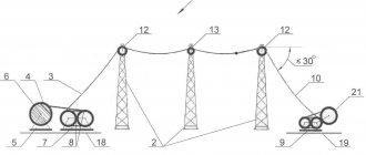
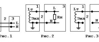
Below are methods for determining phase and neutral wires with the advantages and disadvantages of each option. In any case, first clarify the network parameters. In old houses, for example, a two-wire connection scheme with a single working and grounding conductor is often used.
The figure shows a modern network with separate grounding and working zero connections. It is possible to connect three- and single-phase loads.
Determining the phase using an indicator screwdriver
Touching the tip of such a device to the phase wire closes the current circuit. This is accompanied by the warning lamp or LED lighting up. A built-in resistor limits the current to a safe level.
Advantages of the indicator:
- minimum cost;
- compactness;
- reliability;
- durability;
- autonomy;
- good protection from adverse external influences.
The disadvantage is the limited measurement accuracy. Under certain conditions, false positives cannot be ruled out.
Determination of ground, zero and phase using a test lamp
To reproduce this technology, you need to prepare a simple design. An incandescent lamp designed for the appropriate mains voltage is screwed into a standard socket. Connect wires of sufficient length to perform work operations in a specific location.
Next, connect one of the wires to the known zero line. Others sequentially check other cable cores. Lighting of the lamp indicates the presence of a phase.
Using a measuring device
When checking a 220 V household network, you do not need to know how to determine the polarity. The power supply is organized using alternating current, so set the multimeter switch to the appropriate position. Touching the phase-zero (phase-ground) wires with the probes is accompanied by an indication of the corresponding voltage (≈220 V). The potential difference between the neutral conductor and ground is minimal.
For your information. When checking an old two-wire circuit, one of the probes touches the reinforcement in a concrete slab, a radiator of a heating system, or another grounded element of a building structure.
When switching to constant voltage, the multimeter will show where the plus and minus are. In the absence of reliable information about the electrical parameters in the circuit, they begin with the maximum measurement range with a sequential transition to smaller values with insufficient accuracy.
Such a “device” is useful for testing DC circuits in the absence of specialized measuring instruments. Bubbles near the negative wire are the release of hydrogen during the electrolysis reaction. The area near the plus will take on a greenish tint after a few minutes.
Using LED
You can create a control device with your own hands by analogy with an indicator screwdriver. Instead of a light bulb, install AL 307 or another LED with similar characteristics. A 100-120 kOhm resistor with a power of 1-2 W is added in series to the circuit.
How to independently determine the ground, zero and phase of wires if there are no markings?
Quite often situations arise when the connection is made in an unclear way. Some electricians, even today, may use outdated wiring standards, which is why other specialists have to look for zero and phase using a probe and mark the conductors with the right color with electrical tape or heat-shrinkable tubing of the right color.
Determining the phase using an indicator screwdriver
Inside the probe there is a resistor and a lamp. When the tip of a screwdriver touches the contact and the live conductor, the circuit closes and the lamp lights up. Resistance reduces the current to a minimum, protecting against electrical shock. Thus, it is quite easy to find out which wire is phase.
This is the most preferable option for determining the phase, especially since the cost of the screwdriver is quite affordable. Its main drawback is the possibility of false positives. Sometimes an indicator screwdriver can react to interference and detect the presence of voltage where there is none.
Determination of ground, zero and phase using a test lamp
This method of determination is quite effective, but requires special caution:
- a lamp is screwed into the socket, and wires with the insulation removed at the ends are fixed into its terminals;
- You can also use an ordinary table lamp with an electric plug;
- the technology is quite simple - the lamp wires are alternately connected to the conductors that require identification.
In this way, you can only find out which conductor has a phase. If the control lamp lights up, then this wire has a phase. If the lamp does not light, then there is no phase or zero among the wires. This also cannot be ruled out.
To determine the phase wire, you can connect one of the ends coming from the lamp to a known zero, and then when the second end is connected to the phase conductor, the lamp will light up. The wire that remains will be zero accordingly.
The method of determining phase or zero using a lamp is good for checking the functionality of the wiring.
It should be remembered that when working with electrical wires, care and caution are required.
Core marking for electrical installation solutions
It is not for nothing that at the beginning of the article the idea was voiced that the color designation of conductors greatly simplifies the installation process.
If you independently do electrical wiring in an apartment or private house, select wires according to the standards, when connecting electrical devices, installing automatic protection, distributing wires in junction boxes, you do not need to double-check where the phase, neutral, and ground are - the color of the insulation will tell you about this.
A few examples of electrical installations where marking is important:
There are cables with a large number of cores, the painting of which is not practical. An example is SIP, which uses a different method for identifying conductors. One of them is marked with a small groove along its entire length. The relief core usually performs the function of a neutral conductor, the rest play the role of linear ones.
To distinguish the cores, they are marked with tape, heat shrink, and letter designations, which are applied with multi-colored markers. And in the process of electrical installation work, a ringing is required - additional identification.
The color of the ground wire in a three-core wire
In a three-core wire, in accordance with the rules of the PUE, the grounding wire is marked with the letters PE. Its color is yellow-green. Similarly, marking is carried out on four-core or more cables. In imported cables, the color designation is yellow or green. Another distinctive feature is the diameter of the grounding branch. It may be less than that of a phase wire.
The color of the ground wire in a three-core wire
In some cases, the three-core wire contains a limited gap in the transparent insulation. In this case, a limited cable designation is allowed. The minimum distance from the open electrical wire to the insulation is 15 mm.
Determining the purpose of a wire without color markings
In order to speed up and facilitate maintenance or installation, color marking of wires in electrical wiring is successfully used. Sometimes situations arise when one-color electrical wiring was used, or it was installed by a person who does not inspire confidence. Then, before starting installation, to ensure safety, it is worth checking to see if the purpose of the wire matches the color of the coating.
To achieve this goal, a tester or multimeter is used. All lines are checked for the presence of voltage, its magnitude and polarity. Sometimes it is enough to find out the beginning and end of the line, as well as its color along the entire path.
One device must have conductors with the same colors along the entire line. All circuits are made of conductors with the same shade of insulation. This phenomenon indicates a high quality of installation, and greatly simplifies the repair or maintenance of the device.
All lines must have the same color from the beginning to the end of the path Source lodus.ru
Color of wires plus (+) and minus (-) in DC networks
Is the red wire positive or negative? Such questions arise when working with DC electrical circuits.
Red
To remember which plus is red or black, they use the name of a well-known international organization - the Red Cross. This phrase suggests that red means plus.
Black
Black color indicates the negative conductor. These markings can be seen on typical household equipment:
- power supplies;
- audio, video equipment;
- other devices with electronic software control units.
Plus
The polarity of conductors must be observed when repairing standard electrical equipment of cars. In some situations, confusion with plus and minus is accompanied by a violation of the functional state.
Minus
The high power of connected consumers increases the responsibility for performing repair and adjustment work. In such situations, it is necessary to eliminate errors in determining polarity. Strong direct current is used to supply electricity:
- warehouse and municipal transport;
- lifting mechanisms;
- sensors and automation.
Where is speaker cable used?
In a Hi-Fi system, each loudspeaker is driven by its own electrical signal. Accordingly, the AC passes from each speaker to the receiver or amplifier. The subwoofer is usually connected via a monaural AC. On the other hand, dual core stereo cables are used for speakers. Two copper wires, each carrying an audio signal from the receiver to the box. The following types of cables exist in an audio system:
- Electric - to power all system devices. The most important criterion here is the cross-section.
- A speaker wire that conducts sound, its main role is to provide the best connection between the amplifier and speakers to dissipate the least amount of energy. To achieve this, the resistance of the conductors must be as low as possible compared to the total resistance of the installation.
- An audio cable is a coaxial AC cable consisting of one or more conductors surrounded by a shield. This type can be used for line level signal transmission as well as microphone.
- DMX is a digital signal just like AES/EBU. DMX has an ideal impedance characteristic value of 100 to 120 ohms.
You might be interested in: Features of electrical wires and cables
Coloring phase
In cases where the electrical installation is installed using rigid metal busbars, the tires are painted with indelible paint in the following colors:
- yellow – phase A (L1);
- green – phase B(L2);
- red – phase C (L3);
- blue – zero bus;
- longitudinal or inclined stripes of yellow and green color – grounding bus.
The color of the phases must be maintained throughout the entire device, but not necessarily over the entire surface of the bus. It is allowed to mark the phase designation only at the connection points. On a painted surface, you can duplicate the color with the “ZhZK” symbols for paint of the corresponding colors.
If tires are not accessible for inspection or work when there is voltage on them, then they may not be painted.
The color of phase wires connected to rigid busbars may not coincide with them in color, since there is a difference in the accepted designation systems for flexible conductors and rigid stationary distribution busbars.
Factory standards
Traditionally, when creating three-phase networks, all cables were colored according to the regulatory documentation of previous years. In wiring that is more than 7 years old, according to the PUE, the following markings were strictly observed:
- yellow, possible greenish longitudinal vein - Phase A
- pronounced green color, sometimes neon tint - Phase B
- red.- Phase C
- bluish or neutral gray tone is allowed - Zero
Common three-phase wiring was designated by the abbreviation Zh-Z-K.
If you are dealing with old wiring from the times of the USSR, then the color of the conductors will only be monochrome: black or white. Electricians recommend not to take risks - when disconnecting, you need to turn on the power and determine the type of strands of the electrical wire using a tester.
Since 2011, GOST RF 50462-2009 began to function on the territory of the Russian Federation. It provides new colors for industrial conductors. The acceptable shades for phases are: A - classic brownish, B - rich black, C - gray, close to metallic. But the contrast of such materials turned out to be inconvenient, and electricians, when installing standard systems, still prefer the old ZH-Z-K range to the K-H-S formula. Bright veins are better visible in any lighting, the contrast of the design gives a quick understanding of the situation.
The letter designation makes it easier to recognize the nuances of the circuits: A is L or L1, B is L2 only. C is L3 and zero is N. Therefore, a knowledgeable craftsman will immediately understand what color the phase wire is when composing the circuit.
According to generally accepted standards, when creating AC or DC electrical circuits using protected conductors, all of the above shades are acceptable.
The complete set of the European socket implies the presence of three components: a bright phase one (it can be red, purple, brown or another rich tone), a blue-blue shade that is safe for humans, and protection in a yellow or green color. Wire markings are recognized only as generally accepted.
Wire color coding
Wire colors: ground, phase, neutral
To facilitate the installation of electrical wiring, the cables are manufactured with multi-colored wire markings. Installation of a lighting network and supplying power to sockets requires the use of a cable with three wires.
The use of this color system significantly reduces the time required for repairs and connecting sockets and switches. This scheme also minimizes the qualification requirements for the installer. This means that almost any adult man is able to carry out, for example, installation of a lamp himself.
In this article we will look at how grounding, zero and phase are designated. As well as other color markings of wires.
How to properly check using a multimeter or tester
To carry out the test, a scale is set on the device that exceeds the expected voltage in the network. For residential buildings, it is enough to set the switch to the 250 V position. After this, one probe touches the bare neutral wire (it should have a blue insulation color), and the second to the phase. If the assumptions turned out to be correct, then the indicator shows a figure close to 220 V. The ground wire is checked in this way, but the device shows lower numbers.
Very often, phase, neutral, and ground conductors are not designated by color. Then all pairs are checked and their purpose is determined by indicators.
Determination of phaseSource domamaster.net