Any electrical network needs protection from overcurrents - currents whose strength exceeds the operating value of the electrical circuit. They occur as a result of a short circuit or overload and can damage circuit elements or cause a fire in the conductor insulation.
To protect electrical circuits from possible damage due to short circuits and overloads, special devices called circuit breakers are used.
To protect electrical networks designed for currents up to 125 A, compact modular circuit breakers are used. In circuits where currents of up to 1600 A flow, medium-sized protective devices are used - molded-case circuit breakers. Protection of systems with currents up to 6,300 A is the prerogative of automatic air circuit breakers.
Purpose of automatic air circuit breakers
Air type circuit breakers are used for:
- infrequent switching off and switching on of power electrical networks (in manual mode);
- opening electrical circuits in case of overload or short circuit (in automatic mode);
- automatic de-energization of electrical equipment in order to protect it from breakdowns at low voltage in the network;
- circuit protection in various automatic backup power supply systems, for example, in those that use contactors and magnetic starters.
Description
Devices of this type are subject to certain requirements, including ensuring safe long-term use and reliable protection against overloads and short circuits in the network. The quality of the device has a special role, since the operation of air switches can occur in different temperature and humidity conditions, in the presence of vibration loads and frequent switching. Electrical receivers are under electrodynamic and thermal influence from switches, thanks to which technological losses are minimized and service life is increased.
Automatic air circuit breakers simultaneously control and protect the network. They are classified into several types according to the response time, which is allotted for opening the contacts from the moment of the signal:
- selective;
- standard;
- fast-acting (have a current-limiting function).
Why is the switch called an air switch?
The use of the word “air” in the name of the circuit breaker is associated with the method of extinguishing the electric arc inside the device.
When the switch contacts are opened and closed, an electric arc occurs between them, which must be quickly extinguished to prevent damage to the device.
The poles of the automatic air circuit breaker are not located in separate chambers, but in a single space filled with air and separated by partitions. Thus, the extinction of the arc discharge occurs in the air. Hence the name.
What is it intended for and where is it used?
This type of machines can be used both in industrial enterprises and in private apartments. This is possible due to the variety of their dimensions and the different weights of the devices. They can be not only minimal in size (indoor automatic machines), but also quite large (withdrawable type), which are equipped with a parameter controller.
They are used to protect electrical devices and high-voltage transmission lines from increased current consumption and short circuits. This is achieved by determining the amount of current that flows through the circuit breaker.
The design of automatic air switches is quite simple, which makes them very popular and in demand in the switching device market.
Its advantages include instant network shutdown, internal protection mechanisms, and increased resistance to temperature changes that arise due to the amplitude of the current power.
Main characteristics of the air circuit breaker
One of the main characteristics of an automatic air circuit breaker is the rated current of the release. This is the current for which the device is designed to operate. It flows through the switch without causing it to trip. The device is switched off only if the rated current value is exceeded.
Another important characteristic of the circuit breaker is the ultimate switching capacity (UCC). This is the highest short circuit current that the “air vent” can turn off.
Another important parameter of the machine is switching (electrical) wear resistance. Its value reflects the number of on and off cycles - the operating life of the device.
How does an automatic air circuit breaker work?
When the load of powerful electrical appliances is turned off, the diverging contacts form a kind of arc. Its strength can be equal to the rated current. Such an arc appears as a result of an increase in temperature and the formation of plasma and can melt the contacts of the switching device, as well as cause a short circuit. Needless to say, this usually leads to the failure of expensive equipment. To protect against the effects of this arc, an arc suppression chamber was developed, which is installed in the automatic air circuit breaker. You can find its design in one of the images presented on the Internet.
To avoid mistakes in using the air switch, you should carefully study its design.
Air circuit breaker control
The switch can be controlled either manually or remotely. To manually put it into operation, you need to use a special handle to cock the spring of the release mechanism, and then press the power button. The “air vent” is taken out of operation by pressing the shutdown button.
Remote activation of the device is carried out using a motor drive, which, after power is supplied, automatically charges the spring, and a switching coil that closes the contacts. Another coil that opens the contacts is responsible for disconnecting.
Retractable air circuit breakers
Power air circuit breakers are available in stationary and withdrawable versions. A retractable machine is a system consisting of the device itself and the basket in which it is installed.
The basket is attached to the rails of the input distribution device. It has guides and a chassis for easy racking in and out of the air circuit breaker.
The machine in the basket is moved forward or backward by rotating a special handle. The retractable switch can be in three positions: “Operating”, “Test”, “Off”.
In the operating position, all circuits are turned on - main and auxiliary: the device operates in normal mode. When the switch is pulled out, the contacts of the main circuit open, and the “air vent” is in a position that allows it to be tested. Further rotation of the handle of the retractable mechanism leads to the opening of the contacts of the auxiliary circuit, which allows servicing of the circuit breaker.
Operating principle
When the contacts break, an arc occurs. Reaching the grating of the arc extinguishing chamber, it begins to stretch out, and under the influence of heat, the air in the chamber flows out through the gratings, carrying further with it the products formed by the plasma, stopping its manifestations physically.
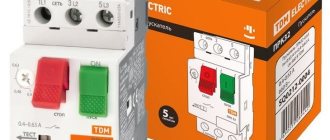
Understanding the processes occurring in switched circuits, as well as methods for suppressing undesirable phenomena, helped create devices that are quite compact in size and weight, capable of interrupting currents of hundreds of amperes. The photo below shows a typical representative of an automatic air circuit breaker:
Examples of application of automatic air circuit breakers
High-current air circuit breakers can be used wherever it is necessary to provide protection for power electrical circuits - both at civil and industrial facilities.
For example, they are used as input circuit breakers in transformer substations (TS) and main distribution boards (MSB) of apartment buildings, into which electrical energy is supplied from the TS.
“Air vents” are also widely used in industry, providing protection for steel-smelting furnaces, rolling mills and other industrial electrical equipment.
Automatic air circuit breakers EKF
The EKF company produces a wide range of circuit breakers, including air circuit breakers of the BA-45 and BA-450 EKF PROxima lines. The VA-45 series combines devices designed for currents from 630 to 5,000 A and having a maximum switching capacity from 80 to 100 kA. “Vozdushnik” 450 series with PKS 80 kA are designed to work with currents from 200 to 1600 A.
EKF automatic air circuit breakers are available in two versions - stationary and withdrawable. The basic package of VA devices includes on and off coils, an electric spring charging drive, a minimum voltage relay and additional contacts to which devices for remote monitoring of the circuit breaker condition can be connected.
The three-phase power automatic machine VA-45 is equipped with an electronic control unit (microprocessor release), the functionality of which is not limited to protection against overload and short circuit. It has a wide range of settings, displays current current indicators for each phase and information about operation parameters. In addition, the VA-45 electronic control system has the functions of thermal memory, short shutter speed, environmental temperature control, testing and self-diagnosis.
VA-450 devices are quite compact devices for air circuit breakers and, regardless of the rating, have the same size. The functions of their electronic control unit include protection against overload, short circuit and ground fault, fault memory, thermal memory and self-diagnosis.
The EKF line of air circuit breakers includes a large number of models, which makes it easy to select the optimal device for a specific project, regardless of its scale and level of complexity.
Automatic air circuit breakers
Automatic air circuit breakers (automatic circuit breakers) are used to automatically shut down an electrical circuit when an overload, a short circuit occurs, the voltage drops below a set value, or a change in the direction of energy transfer occurs. They are also used as manually controlled switching devices for infrequent switching on and off of electrical energy consumers, for example, low-power electric motors. Circuit breakers are called “air” because the extinguishing of the electric arc at the switching contact occurs in the air. The protection unit with a circuit breaker (AB) is discussed in paragraph 5.1, Fig. 5.1a.
Depending on the type, the AB can perform one or more protection functions. For example, installation
The machine in most versions protects the electrical circuit from short circuits and overloads.
For this purpose, it is equipped with sensing elements - releases
, similar in principle to the sensing elements of the electromagnetic overcurrent relay and electrothermal relay. The machine, which protects the electrical circuit from excessive voltage drop, has a release similar to the sensing element of the electromagnetic minimum voltage relay.
The maximum release (responsive to short circuit current) and minimum release (responsive to voltage reduction) are essentially an electromagnetic mechanism (see [1], paragraph 4.1) with an armature drawn into the coil under the influence of an electromagnetic traction force. The anchor acts on the latch of the mechanical transmission (see [1], paragraph 3.2), which (MP) is called the free release mechanism
. A manual drive is also provided for this mechanism so that a person can turn the machine on and off.
In circuit breakers that perform the function of protection against changes in the direction of energy transfer (from “reverse current”, from “reverse power”) there is an independent release
, designed as an electromagnetic mechanism. Some machines use releases that operate on the principle of an electrodynamic converter (see [1], section 3.4.), as well as semiconductor releases.
An automatic air circuit breaker with several types of protection is presented in the block diagram in Fig. 5.7.
An automatic air circuit breaker (ABC) acts on the electrical circuit it controls (ECC) with a switching contact (CC), changing the resistance ( RK
) chains. When the CC is open, the electrical energy receiver (EER) is disconnected from the power supply from the electrical energy source (IEE). The number of switching (main) contacts can be from one to three. The contact system includes devices for extinguishing the electric arc, usually arc extinguishing grids (see [1], clause 2.8). In some machines, additional arc-extinguishing contacts are installed, and auxiliary contacts may be provided for switching low-current signaling and control circuits.
Depending on the type of machine, its release unit (UR) consists of a certain combination of releases from the following composition:
P1 – undervoltage release U
(
minimum release
that responds to voltage reduction);
P2 – overcurrent release I
(
maximum release
responding to short circuit current);
P3 – independent release to which the signal Unpe
, carrying information, for example, about a change in the direction of energy transfer in the electronic digital signature circuit;
RT – overload current release (thermal release that responds to overload current).
Installation machine UR unit
with a combined release consists of releases P2 and RT.
The universal automatic machine
has releases P1, P2. Depending on the purpose and the composition of the release assembly, there are also maximum current circuit breakers, minimum current circuit breakers, maximum circuit breakers that respond to the derivative of the current with respect to time, etc. [9]. To build selectively acting protection, the AV provides the ability to adjust the current and response time.
Each of the releases independently acts on the free release mechanism (MSR), removing the stop from the mechanical transmission latch (see [1], paragraph 3.2). This leads to the opening of the switching contacts of the CC. Therefore, the disconnection of the damaged section of the ECC electrical circuit and the PEE receiver will occur when at least one of the monitored parameters of the ECC circuit goes beyond the range of permissible values determined by the corresponding settings of the releases. Turning on the automatic machine for closing the electrical circuit of the ECC and turning off the automatic machine for opening the circuit is carried out by a person using the influence of hvkl
and
hotk
to the lever or push-button manual control unit (MC) of the machine (Fig. 5.7).
In Fig. 5.8a shows an electrical diagram illustrating the connection of the installation machine to a three-phase network and its symbol on the diagram. The action of the machine (QF) when the engine (M) is automatically turned off by a combined overcurrent and overload current release is represented using the time-current characteristic, which is given in the machine's passport. A typical type of time-current (protective) characteristic of an installation machine with a combined release is shown in Fig. 5.8b.
Section ab
The time-current characteristic is created by an electrothermal release that performs the function of overload current protection at
I >IPT
, where
IPT
is the setting of the operation current of the electrothermal release (at
taver
>>
TP
- see paragraph 5.3).
Section c-d
is due to the action of the electromagnetic overcurrent release.
The response time τср of
the circuit breaker from the electromagnetic release practically does not depend on the current strength
I
if the current strength exceeds the setting
IPEM
of the electromagnetic release.
Depending on the speed of operation, there are: 1) normal automatic machines, whose own response time is 0.02...0.1 s; 2) selective circuit breakers that provide a shutdown delay of up to 1 s; 3) high-speed automatic machines, the response time of which is thousandths of a second.
The machines are produced for alternating voltages from 220 to 660 V and constant voltages from 110 to 440 V. The most widely used machines are the following series:
AZ000 is the most common series. Designed for alternating voltages 380, 660 V, constant voltages up to 440 V. Switched currents (switching capacity) up to 60 kA.
AE1000, AE2000 - for protecting circuits and electrical receivers from overload and short circuits. Voltages: alternating 380, 660 V, constant 110, 220 V. Switched currents from 1 to 10 kA.
"Electron" - for installation in switchgears for direct voltage up to 440 V and alternating voltage up to 660 V. Switched current from 50 to 160 kA.
Automatic air circuit breakers of the AP-50 series are used for voltages up to 500 V AC and up to 220 V DC. The manual drive has two buttons - one to turn on, the other to turn off the machine. The switch has an electromagnetic release and an electrothermal release. The rated current of the releases is up to 50 A. The setting of the electrothermal release can be adjusted by 30...40% downward relative to the rated current.
Automatic machines are selected according to the number of poles, rated current and voltage values. Rated voltage values UNav
and current
INav
of the machine in relation to the rated value of the network voltage
UNnetwork
and the rated load (motor)
current ILdv
must satisfy the following conditions:
UNav
≥
UНnetwork
,
INav
≥
IНдв
.
IPT settings
,
IPEM
currents for protecting an electric drive motor are usually determined as follows:
for electrothermal release (overload protection) – according to the rated motor current IНдв
,
IPT≥
(1,2…1,4)
IНдв
;
for an electromagnetic release (short circuit protection) - according to the highest value of the current of any transient process Iper
(start, reverse, braking),
IPEM ≥
(1,5…2,0)
Iper
.
Maximum circuit breaker current
must be no less than the possible short circuit current in the circuit.
Engine protection devices for automatic motors
(MS, GV series, there are no domestic analogues yet) with a combined release are specially designed for use in electric motor protection circuits. They have some features:
• are available only in three-pole versions;
• designed for rated currents from 16 to 100 A;
• the rated current of the motor is set on the machine (GV series) using an adjustment dial;
• have precise adjustment of the thermal release;
• the setting of the electromagnetic release is, as a rule,
(12 … 14)INav
, which corresponds to the operation of the machine on an inductive load (starting mode AC-3);
• switches have high electrodynamic resistance – up to 100 kA;
• switches have a lever or buttons on the body for manually turning on and off the load;
• the housing design makes it possible to combine an automatic machine and a starter matched in size into a single compact unit;
• switches have either built-in or mounted quick-mounted additional contacts that are triggered by overloads and short circuits;
• the depth of protection of the electric motor can be increased due to separately supplied quick-mounted elements - an independent release and a minimum voltage relay.
