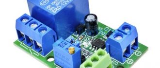
We know that the resulting voltage at the output of the thermocouple is very low and Arduino cannot measure it.
To solve this problem, we need to assemble a thermocouple amplifier so that the output voltage is about 5 volts at 1000 degrees temperature. I did this experiment on the LM358 chip and assembled an amplifier for a thermocouple. I started doing experiments on the amplifier. I achieved the results shown in the video. If the results are satisfactory, I will make a thermocouple module to connect it to Arduino.
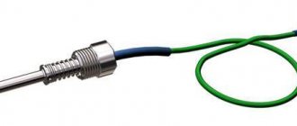
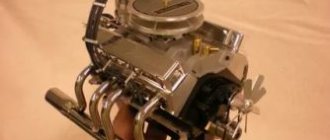
Thermocouple amplifier on LM358. The thermocouple KTHK-40 is used in the experiments. 400 C.
Several years ago I was faced with the need to measure temperature using thermocouples. One person helped me significantly in this, to whom I am still grateful. Without going too much into theoretical aspects, I want to offer a simple version of a thermocouple amplifier. This amplifier has been repeated by several people and good results have also been obtained.
Basic scheme.
The basis of the amplifier is taken from the technical description for the operational amplifier OR213. This op-amp can be classified as an accurate op-amp with low thermal zero drift
I’ll say right away that an unfortunate mistake was made on the proprietary diagram. The connection point between resistors R8 and R6 must be excluded. The circuit allows you to measure temperature in the range 0 - 1000 o C with an accuracy of 0.02 o C when using this op-amp and a K-type thermocouple. This thermocouple has the closest thermoelectric characteristic to direct. Thermoelectrodes are made of nickel-based alloys. Chromel (HX9.5) contains 9.10% Cr; 0.6. 1.2% Co; alumel (NMtsAK) - 1.6. 2.4% Al, 0.85. 1.5 Si, 1.8. 2.7% Mn. 0.6. 1.2% Co. Alumel is lighter in color and is weakly attracted by a magnet; in this it differs from completely non-magnetic chromel, which is darker in the annealed state. Due to their high nickel content, chromel and alumel are superior to other base metals in terms of oxidation resistance. Considering the almost linear dependence of the thermoEMF of the chromel-alumel thermocouple on temperature in the range of 0.1000°C, it is most often used in thermostats.
Connecting the thermocouple electrodes to the amplifier board connectors creates another source of thermoEMF (cold junction), the voltage at which introduces a significant error in the true readings. To eliminate this error, different methods are used. In this case, a simple and effective method is used to compensate the cold junction voltage. A silicon diode is connected as close to the connector as possible. The known dependence of the pn junction current on temperature makes it possible to generate a compensation voltage to correct the cold junction error.
The op-amp is powered by a voltage of +12V, the maximum output voltage of the op-amp will be, due to the internal voltage drop, slightly more than 10V. The op-amp circuit represents an amplifier with feedback with coefficient. gain is about 200. Resistor R6 balances the op-amp reference voltage (zero setting).
The REF02EZ precision voltage stabilizer allows you to obtain a stabilized voltage from the supply voltage to power the input dividers of the op-amp with an accuracy of about 1 mV.
The resistor values, especially the input dividers, should match those shown on the diagram as closely as possible.
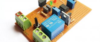
Practical implementation.
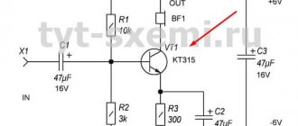
This circuit is good for everyone, but the components are not cheap, and the declared accuracy is not always needed in most cases. The most common task is to measure temperatures up to 400 o C with an accuracy of +/- 1-2 o C. A simple and cheap circuit was developed for this task.
The support stabilizer is not used; the cheaper and more common op-amp LM358 is used. The supply voltage is 5V, so the maximum you can actually measure is 375 °C. The relatively large temperature drift of the op-amp determines the measurement error, no more than 2 °C. To increase noise immunity to alternating current, capacitor C1 is used. Resistor R12 can be used to adjust the gain depending on the thermocouple used. In the range up to 400 °C, many types of thermocouples are linear enough that any suitable thermocouple can be used. Good results are obtained with thermocouples from digital multimeters. Since the LM358 chip contains two op-amps, it is convenient to implement a two-channel version on one chip.
Manufacturing features.
It is advisable to place the temperature compensation diode at the bottom of the printed circuit board, so that its body is as physically close to the connector as possible. It's good to apply thermal paste. Resistors can be used either SMD type or regular 0.125 W. I usually use standard series resistors.
2.74K=2.7K+39
53,6=27+27
3.95K=3.9K+51
Calibration
At home, calibration is easiest to do using two points, 0 and 100 degrees. The thermocouple is immersed in melt water, the reading is set to 0 degrees R6. The thermocouple is immersed in boiling water and the reading is set to 100 degrees R12. Check 0 and 100 again and adjust if necessary. You can check your body temperature to 36.6 degrees.
LM358 pinout
Since the LM358 contains two operational amplifiers, each with two inputs and one output (6 pins) and two contacts needed for power supply, a total of 8 contacts are obtained.
LM358 are packaged in both volume-mount packages (LM358N - DIP8) and surface-mount packages (LM358D - SO8). There is also a metal-ceramic version for particularly difficult working conditions. I used the LM358 only for surface mounting - it’s easy and convenient to solder.
Analogs LM358
Complete analogs of LM358 from different manufacturers NE532, OP04, OP221, OP290, OP295, OPA2237, TA75358P, UPC358C. For LM358D - KIA358F, NE532D, TA75358CF, UPC358G.
Along with the LM358, a large number of similar operational amplifiers are produced. For example, LM158, LM258, LM2409 have similar characteristics, but different operating temperature ranges.
| Type | Minimum temperature, °C | Maximum temperature, °C | Supply voltage range, V |
| LM158 | -55 | 125 | from 3(±1.5) to 32(±16) |
| LM258 | -25 | 85 | from 3(±1.5) to 32(±16) |
| LM358 | 70 | from 3(±1.5) to 32(±16) | |
| LM358 | -40 | 85 | from 3(±1.5) to 26(±13) |
If the range of 0..70 degrees is not enough, then you should use LM2409, however, you should take into account that its power range is narrower:
By the way, if you need only one operational amplifier in a compact 5-pin SOT23-5 package, then you can easily use LM321, LMV321 (analogues of AD8541, OP191, OPA337). On the contrary, if you need a large number of adjacent operational amplifiers, then you can use quad LM324 in a 14-pin package. You can completely save space and capacitors on power circuits.
Description of the LM358 chip
Confirmation of the high popularity of the microcircuit is its performance characteristics , which allow the creation of many different devices. The main indicative characteristics of the component include the following.
Acceptable operating parameters: the microcircuit provides single and bipolar power supply, a wide range of supply voltages from 3 to 32 V, an acceptable slew rate of the output signal equal to only 0.6 V/μs. Also, the chip consumes only 0.7 mA, and the offset voltage is only 0.2 mV.
Read also: Slavyanka motor winding diagram
LM358 switching circuit: differential amplifier
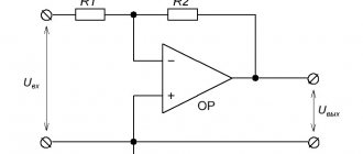
This high input impedance differential amplifier circuit can be used to measure voltage from sources with high internal impedance. Provided that R1/R2=R4/R3, the output voltage can be calculated as: Uout = (1+R4/R3)(Uin1 – Uin2). The gain will accordingly be equal to: (1+R4/R3). For R1 = R2 = R3 = R4 = 100 kOhm, the gain will be 2.
Thermocouple signal amplifier
Bibliographic description:
Galimullin, N. R. Thermocouple signal amplifier / N. R. Galimullin, N. T. Khairullina. — Text: direct // Research of young scientists: materials of the III International. scientific conf. (Kazan, October 2021). — Kazan: Young scientist, 2021. — pp. 1-3. — URL: https://moluch.ru/conf/stud/archive/349/15255/ (access date: 08/01/2021).
This article is devoted to the development of a thermocouple signal amplification device.
Key words: thermocouple, temperature control, nichrome spiral.
In addition to the task of temperature control, it may be necessary to ensure its regulation or maintenance at a given level. Therefore, it becomes important to ensure coordination between the temperature measurement unit and the heater, which can be a nichrome spiral. For the heater to operate, it is necessary to amplify the signal from the power measurement unit, so the thermal control device also includes a power amplifier.
This article discusses various types of thermocouples, which are often the main type of temperature sensors. A thermocouple signal amplifier and a power amplifier are being developed to control the heating element.
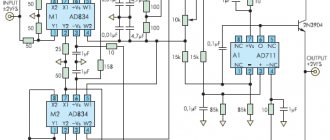
The electrical circuit of the temperature measurement unit and the heating unit are shown in Figures 1 and 2. Let us consider them separately.
S-type thermocouples are the most wide-range and stable, so they are widely used [1]. However, they have a serious drawback: an extremely low conversion coefficient, only 5.88 µV/°C at 20°C (type J thermocouple - 51.45 µV/°C, type K - 40.28 µV/°C). Therefore, at not very high temperatures (less than 500°C), the signal they produce is extremely small. The amplifier must reject the 50 Hz signal well and have stable differential gain. Its input impedance must be high enough (more than 10 kOhm).
Rice. 1. Temperature measurement unit
We have developed a scheme (Fig. 1) that allows us to solve these problems. It is presented in the form of a differential amplifier with a T-shaped feedback circuit, which has a fairly high voltage gain (200) and a fairly high input impedance. As an operational amplifier, it is best to use a precision amplifier with extremely low offset (less than 10 μV) and equally low temperature drift (less than 100 nV/°C). These amplifiers include the LTC1050, LTC1052 from Linear Technology, the ICL7650, ICL7652 from Intersil and Maxim, and the AD8551 from Analog Devices. The supply voltage (from +UPIT to -UPIT) of this amplifier is 12 V.
Shunt capacitors at the amplifier input reduce RF interference (since the thermocouple connecting wires are quite long).
The AD590 chip, which is in thermal contact with the reference junction, is used as a temperature sensor, generating a current proportional to its absolute temperature (1 μA/°C). A temperature of 0°C corresponds to an absolute temperature of 273 K, and therefore the AD590 will produce a current of 273 µA; temperature 25°C - 298 K and 298 µA, respectively, etc.
Since the main amplifier DA2 has a gain of 200, the compensating voltage generated by the amplifier DA1 should be 200 • 5.88 = 1.176 mV/°C. This is ensured by including a resistor with a resistance of 1.176 kOhm in the feedback DA1.
If the reference junction is at a temperature of 0°C, zero voltage should be present at the DA1 output, since at zero temperature of the reference junction no correction is needed. However, the AD590 in this case produces a current of 273 μA, which, passing through a resistor with a resistance of 1.176 kOhm, creates a voltage drop across it of 0.321 V. In order to compensate for this signal, the non-inverting input DA1 is supplied with voltage from the voltage divider R2-R4, which forms together with precision zener diode VD1 (LM336Z-2.5) required voltage. Fine adjustment is carried out by trimming resistor R4.
When using other types of thermocouples, it is necessary to recalculate the value of resistance R5 and the correction voltage at the non-inverting input DA1, which may require the use of a higher voltage reference voltage source.
The basis of the heater block is a heating element, which uses a nichrome spiral, and the block itself is a DC power amplifier. The control voltage comes from the output of the temperature measurement unit and is supplied to the input of the amplifier, where it is amplified in power and then supplied to the heating element. Thus, the voltage on the heating element and the power dissipated by it (heating temperature of the coil) depend on the control voltage. The power amplifier is assembled according to a standard design. The input part is assembled according to a differential amplifier circuit (DA1), in which one input is connected to a common wire. The output part is assembled according to a voltage booster circuit using transistors VT1-VT6.
The output voltage of the amplifier can vary from +16 V to –16 V.
Rice. 2. Heating block diagram
This electronic unit is complete and can work either independently as a temperature controller or as part of an electronic system where thermostatting or temperature control is required.
Literature:
- GOST R 8.585–2001. GSI. Thermocouples Nominal static characteristics.
Key terms
(automatically generated)
: heating element, power amplifier, reference junction, absolute temperature, amplifier input, input resistance, differential amplifier, feedback, resistance resistor, thermocouple type.
LM358 switching circuit: differential amplifier with adjustable gain
It is worth noting that the previous circuit does not allow you to adjust the gain, since it requires simultaneous changes in two resistors. If you need to be able to adjust the gain in a differential amplifier, you can use a circuit with three operational amplifiers. In this circuit, the gain is adjusted by adjusting resistor R2. For this circuit, it is necessary to meet the conditions for equality of resistor resistance values: R1 = R3 and R4 = R5 = R6 = R7. Then the gain will be equal to: (1+2*R1/R2). Uout = (1+2*R1/R2)(Uin1 – Uin2).
Popular circuits for lm358
There are various devices assembled on the LM358 N that perform specific functions. In this case, these can be all kinds of amplifiers, both UMZCH and in intermediate circuits for measuring various signals, an LM358 thermocouple amplifier, comparing circuits, analog-to-digital converters, etc.
Non-inverting amplifier and voltage reference
These are the most popular types of wiring diagrams used in many devices to perform various functions. In a non-inverting amplifier circuit, the output voltage will be equal to the product of the input voltage and the proportional gain formed by the ratio of two resistances included in the inverting circuit.
The voltage reference circuit is highly popular due to its high practical performance and stability in various modes. The circuit perfectly maintains the required output voltage level. It has been used to build reliable and high-quality power supplies, analog signal converters, and in devices for measuring various physical quantities.
Sine Wave Generator
One of the highest quality sine wave generator circuits is the Wien bridge device . With the correct selection of components, the generator produces pulses in a wide range of frequencies with high stability. Also, the LM 358 chip is often used to implement a rectangular pulse generator of various duty cycles and durations. At the same time, the signal is stable and high quality.
Amplifier
The main applications of the LM358 chip are amplifiers and various amplification equipment. This is ensured due to the inclusion features and selection of other components. This circuit is used, for example, to implement a thermocouple amplifier.
Thermocouple amplifier on LM358
Very often in the life of a radio amateur it is necessary to monitor the temperature of some devices. For example, on a soldering iron tip . You can’t do this with an ordinary thermometer, especially when you need to create an automatic control circuit. For this, you can use the LM 358 op-amp. This microcircuit has a low thermal zero drift, and therefore is classified as high-precision. Therefore, it is actively used by many developers for the manufacture of soldering stations and other devices.
Read also: Recommend an electric grill for home
The circuit allows you to measure temperature in a wide range from 0 to 1000 o C with a fairly high accuracy of up to 0.02 o C. The thermocouple is made of a nickel-based alloy: chromal, alumel. The second type of metal has a lighter color and is less susceptible to magnetization; chromal is darker and magnetizes better. Features of the circuit include the presence of a silicon diode, which should be placed as close as possible to the thermocouple. When heated, the chromal-alumel thermoelectric pair becomes an additional source of emf, which can make significant adjustments to the main measurements.
Simple current regulator circuit
The circuit includes a silicon diode . The transition voltage from it is used as a source of a reference signal, supplied through a limiting resistor to the non-inverting input of the microcircuit. To adjust the stabilization current of the circuit, an additional resistor is used, connected to the negative terminal of the power supply, to the non-inverting input of the MS.
The circuit consists of several components:
- A resistor supporting the op-amp with a negative terminal and a resistance of 0.8 Ohms.
- A resistive voltage divider consisting of 3 resistances with a diode serving as a reference voltage source.
An 82 kOhm resistor is connected to the negative of the source and the positive input of the MS. The reference voltage is formed by a divider consisting of a 2.4 kOhm resistor and a directly connected diode. After which the current is limited by a 380 kOhm resistor. The op-amp controls a bipolar transistor, the emitter of which is connected directly to the inverting input of the MS, forming a negative deep connection. Resistor R 1 acts as a measuring shunt. The reference voltage is formed using a divider consisting of a diode VD 1 and a resistor R 4.
In the presented circuit, provided that resistor R2 with a resistance of 82 kOhm is used, the stabilization current in the load is 74 mA at an input voltage of 5V. And when the input voltage increases to 15V, the current increases to 81mA. Thus, when the voltage changes by a factor of 3, the current changes by no more than 10%.
Charger for LM 358
Chargers with high stabilization and control of the output voltage are often made using the LM 358 op-amp As an example, you can consider a USB-powered Li-ion charger. This circuit is an automatic current regulator. That is, as the voltage on the battery increases, the charging current drops. And when the battery is fully charged, the circuit stops working, completely closing the transistor.
At the + and - inputs, install voltage dividers consisting of a thermal resistance and an MLT resistor (four resistances of 100K each). To the minus of powering the thermal resistance to the plus of the MLT, i.e. to register the temperature difference in the garage and outside. Power the circuit from 4.5 Volt elements. Question . How will the accuracy of the setting decrease as the voltage decreases from 4.5 V to 3.5 V. Thank you. Where to read so you can understand it yourself.
Let's apply a reference voltage of 1.5 volts to the non-inverting input of the amplifier, and a sinusoidal signal with an amplitude of 1 volt and a constant component of 1.5 volts to the inverting input.
Vcc – 1.5= 5 – 1.5 = 3.5 V
That is, as long as the input signal is less than the reference signal, the output of the operational amplifier will have a positive saturation voltage. As soon as the input signal exceeds the reference signal, the output voltage of the operational amplifier will become zero.
The described circuit is an inverting comparator. If we swap the voltage sources, we get a non-inverting comparator. Try to figure out for yourself how the circuit will behave.
The electrical circuit of an inverting Schmitt trigger is shown below.
Thanks to this behavior of the circuit, a noisy signal will not cause oscillations at the amplifier output.
Like the simplest comparator circuit, the Schmitt trigger has a “non-inverting version,” but we won’t dwell on it here.
About the calculation of such a scheme and examples of its use in the next article...
LM358 connection circuit: current monitor
Another interesting circuit that allows you to measure the current in the supply wire and consists of a shunt R1, an operational amplifier npn - transistor and two resistors.
- DA1 – LM358;
- R1 – 0.1 Ohm;
- R2 – 100 Ohm;
- R3 – 1 kOhm.
The operational amplifier supply voltage should be at least 2 V higher than the load voltage.