What is a capacitor tester
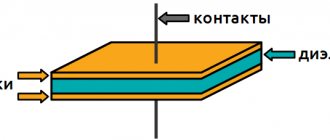
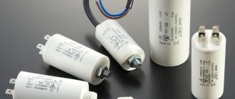
A capacitor is a radio component consisting of two plates made of conductors and a dielectric layer between them. The electrical capacitance of an element is measured in farads. This value is very large, so in practice microfarads or picofarads are used.
Performing a capacitance measurement
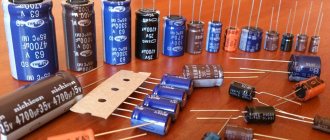
Capacitors are usually electrolytic or film. In the latter, the parameters change little over time. The electrolytic situation is different. The liquid composition inside gradually dries out, and the part loses its beneficial properties. Often you cannot judge its serviceability by its appearance. To check it you need to unsolder it.
Another situation when it is important to check the capacity is when its operation is disrupted due to various reasons of a random nature - power surges or operation at elevated temperatures. A faulty element can cause the entire device to malfunction.
To study the situation, it is necessary to determine whether the capacitance of the capacitor corresponds to the nominal value. Capacitor testers are used for this purpose.
They can be digital or analog. The test may determine capacitance or ESR, a parameter that represents equivalent series resistance.
High precision measurement
Some multimeters have the ability to directly test capacitance.
ESR meters measure equivalent series resistance. Here we are talking about reactance, which is caused by capacitance. It can increase significantly with increasing frequency. This parameter is estimated using complex algorithms. If it takes on too large a value, then in some situations the temperature regime of the element’s operation may be disrupted. This is especially dangerous for electrolytic cells.
You may be interested in this All about screwdrivers
There are special capacitance meters.
Analog device
ESR meter
This measuring device is equipped with a liquid crystal display. It has 2 probes: red and black. The first is considered positive, the second - negative. Before checking, the element is discharged by short-circuiting the leads to each other. To carry out the measurement, the probes are connected to the terminals of the capacitor. If a polar model is used, the polarity of the probes must be taken into account.
Then the device is turned on and after a few seconds the capacitance and ESR parameter values appear on the screen.
Capacitance meter
Multimeter
To determine the health of the capacitor, the multimeter can be switched to resistance determination mode. The switch must be set to 2 MOhm or 200 Kom. It is necessary to select this parameter in such a way that charging does not occur immediately, but within a few seconds.
The red and black probes are connected to its terminals of the element that needs to be removed from the circuit. Now you need to monitor the data on the display. If there is 0, then this means broken contacts or other mechanical damage. If the tester shows increasing numbers and eventually 1 appears, then this indicates the performance of the part. If one appears immediately, this means that a breakdown has occurred in the capacitor.
When using an analog device, you will be able to see a gradual movement of the needle on a working part. An instantaneous setting of the minimum value indicates a break, and the maximum value indicates a breakdown.
The multimeter provides the ability to directly measure capacitance. To do this, you need to set the switch of the device to measure it and select the most suitable scale. Typically, special terminals are provided for the capacitor contacts. If they are not there, you need to use the red and black probes. In the latter case, you must use the same terminals as when measuring resistance.
If the capacity value is equal to or close to the nominal value, then the element is serviceable and can be used. Otherwise it is inoperative. It is believed that a match with a difference of no more than 20% indicates the radio-technical suitability of the part.
Electrolyte leak
ESR. Methods of measurement.
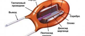
ESR - Equivalent Series Resistance, as one of the significant parasitic parameters of electrolytic capacitors, has gained wide popularity among electronic equipment repairers in recent years. ESR meters and probes have become an essential tool for many craftsmen, along with a tester or multimeter. An increase in the ESR of a capacitor by several Ohms, and sometimes by several tenths of an Ohm, may cause the device in which it is installed to malfunction, which is sometimes impossible to detect with existing capacitance meters that are not able to take into account other parameters of the capacitor.
Typically, in repair practice, special accuracy in measuring ESR is not required, so a noticeable error in probes often does not cause inconvenience in finding faulty elements, and determining the condition of a capacitor with a probe can be simplified to assessing its quality based on the principle of whether it is suitable or not suitable for work in a specific unit of the device. But it should be noted that for capacitors operating at high pulse currents, for example, in converter filters, a more objective assessment of quality is sometimes required, and an error of tenths or even hundredths of an Ohm can be significant.
In the figure you can see that in the operating frequency range of the converters (several tens of kHz), the reactance of a large capacitor and parasitic inductance in a series circuit have values that are an order of magnitude less than ESR and AC impedance. Consequently, almost the entire current, which in a pulse can reach tens of amperes, will release active power into the resistance (ESR), heating the dielectric and electrolyte of the capacitor.
The loss tangent indicated in the technical documentation of manufacturers of electrolytic capacitors for a frequency of 120 Hz (typical value 0.1-0.22) loses its relevance at the operating frequencies of SMPS converters and for filter capacitors of their secondary rectifiers it will be orders of magnitude greater. To operate in such modes, manufacturers manufacture low impedance capacitors (Low impedance) and indicate for them the impedance value measured at a frequency of 100 kHz for each rating in the tables. The value of the active component (ESR) can then be calculated using the formula R = √(Z² - X²)
.
For example, for a Jamicon 1000uF 25V WL series capacitor the Z value is indicated as 0.04 Ohm, taking into account its reactance Xc
= 0.0016 Ohm for the specified frequency, the ESR value can be calculated.
In milliohms this will be approximately 39.97 mOhm, which is practically no different from the value Z = 40 mOhm. The loss tangent for this case R/Xc
will be 39.97/1.6 approximately 25. Parasitic inductance is not used in the calculations here, but in some cases it can be significant.
Most of the popular ESR instruments and probes used in repair practice are based on measuring the impedance of alternating current at a frequency of 40 - 100 kHz. At frequencies of this order, for electrolytic capacitors of large values, such devices will show values as close as possible to the ESR value, which will make up the bulk of the impedance at these frequencies. The disadvantage of this method is a significant error when measuring small capacitance values (less than 10 uF), when the reactance of the capacitor at a given frequency is comparable and can exceed ESR. Then the device will show the impedance value, and the real ESR value may be several times less.
One of the requirements for the practicality of using ESR probes is the ability to take measurements without removing the capacitor from the board. Consequently, the measurement process must occur with a sufficiently low voltage drop across the capacitor being tested, excluding the unlocking of the transitions of the semiconductor elements of the circuit.
In most cases, craftsmen assemble such simple impedance meters themselves using diagrams widely available on the Internet, but some also use their own designs, taking into account personal preferences in terms of ease of use or measurement accuracy. On sale there are both simple probes with LED or dial indication, and meters with a digital scale of varying degrees of complexity.
There is no need to dwell in detail on the principles and methods of impedance measurement; there are quite a lot of such discussions and descriptions and they are not difficult to find on the Internet. But some features of individual designs may still deserve attention.
This article proposes to consider one of the ways to measure ESR and capacitance as separate parameters of a capacitor.
A fairly accurate and simple method, which is used in many amateur and industrial devices, is implemented in the Micro meter, popular among craftsmen - participants in the repair forums monitor.net.ru and monitor.espec.ws.
If the tested capacitor with capacity C
charge from a constant current source
I
, the voltage at its terminals will increase linearly from the value
UR
according to the law:
C dU/dt = I = const
.
UR
– voltage drop across the active resistance of the capacitor (ESR).
In this case, the capacitance of the capacitor will be determined by the expression:
C = Idt/dU
.
If we calculate the charging time for two fixed voltage values U1
and
U2
, taking the value of
U2
twice as large as
U1
, the calculation of the capacity will be as follows:
Calculate UR
to calculate ESR, you can do it in several ways, for example, by composing a straight line equation using two points and finding the Y coordinate for the zero value of X, or geometrically, based on the ratio of the sides of similar triangles...
The active resistance of the capacitor (ESR) in this case will be:
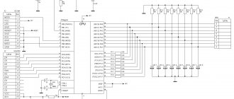
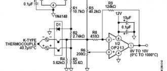
To implement this method, there is no need to use an ADC; the threshold voltage values for controlling the timer are set by comparators, and mathematical calculations of capacitance and ESR are performed by a microcontroller with information displayed on the LCD display.
Some similar designs use a simpler but less accurate method to measure ESR. UR is measured
via an ADC at the initial time. Despite the fact that the measuring pulse is quite short (1-2 uS), capacitors of smaller capacity have time to charge to a higher value than capacitors of large capacity, which creates some error in measuring ESR of different capacitor values.
Please note that ESR, measured by DC current, is a relative indicator of the quality of an electrolytic capacitor. A significant component of ESR is dielectric losses, which vary significantly with alternating current frequency.
There are more complex and accurate measurement techniques and methods based on analysis of the phase shift in the capacitor. In this case, ESR is determined by the product of impedance and loss tangent.
Comments and suggestions are accepted and welcome!
Operating principle of the device for testing capacitors
Before taking measurements, you need to discharge the capacitor. To do this, its terminals are connected to each other.
The multimeter's probes provide a potential difference that can be used to charge a capacitor. Based on the charging time, you can roughly estimate the capacity. By measuring the resistance, you can determine the presence of damage or breakdown of the capacitor.
You might be interested in: The best models of screwdrivers
When measuring the ESR parameter, complex algorithms are used. This tester uses special chips to control the testing process.
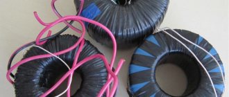
Types of capacitors
How to make a device for testing capacitors with your own hands
You can measure capacitance using a simple device. It requires the following parts:
- DC source;
- resistor;
- capacitor;
- voltmeter.
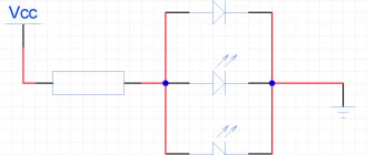
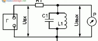
This circuit is suitable for testing electrolytic capacitors. You need to choose the input voltage so that it is slightly less than the rated voltage of the capacitor. One of the terminals of the capacitor is connected to the power source through a resistor. A voltmeter is connected to the terminals of the capacitor.
Test scheme
After connecting the meter, the process of charging the capacitor begins. You need to note the time during which it will last. The amount of resistance can be selected largely arbitrarily. In this case, you need to focus on the charging speed. It needs to be something that is convenient to measure.
When charging, you can see an increase in voltage on the voltmeter. At some point it will reach a maximum value and stop growing. This will be the final moment of the countdown. To calculate the capacity, just use the formula: t=RC. In it, the time and value of the resistor resistance are known. Capacitance can be determined from the ratio C=t/R.
Using a Multimeter
The capacitor is checked for breakdown using a homemade circuit - a 40 W light bulb connected in series with it, connected to a regular AC network. If the light bulb shines at half intensity, then the part is working properly. In bright light there is a breakdown, in the absence of it the contacts are damaged.
How to use the device correctly
If the nominal voltage is unknown, then you can act on the basis that it is 10-12 V. Typically, resistors with a resistance of 5-10 KOhm are used.
To check a part without removing it from the circuit, you can connect a capacitor with the same parameters in working condition in parallel with it. If the circuit restores its operation, this means that the part was faulty and should be replaced.
You may be interested in Installing an ammeter
Bridge circuit
Measuring capacitance without desoldering the board is difficult and only accessible to a professional specialist. A device for testing electrolytic capacitors without desoldering can only be used taking into account the connection diagram of the capacitor. The fact is that the result obtained will significantly depend on the method of connecting the part and in various situations may show results that are difficult to explain. For example, if a coil is connected in parallel with it, then when measuring capacitance without soldering, zero resistance will be shown.
If the capacitor is faulty, you need to check it using one of the available methods. In the event of a malfunction, it will need to be replaced in order for the board to restore its functionality.
Measuring capacitance of a capacitor with a multimeter and special devices
Some multimeters have a capacitance measurement feature. Take these common models: M890D, AM-1083, DT9205A, UT139C, etc. There are also digital capacitance meters on sale, for example, XC6013L or A6013L.
Using any of these devices, you can not only find out the exact capacitance of the capacitor, but also make sure that there is no short circuit between the plates or an internal break in one of the terminals.
Some manufacturers even claim that their multimeters can test the capacitance of a capacitor without desoldering it from the board. Which, of course, contradicts common sense.
Unfortunately, testing a capacitor with a multimeter will not help determine the most important parameters such as leakage current and equivalent series resistance (ESR). They can only be measured using specialized testers. For example, using a very inexpensive LC meter.