| 10uF ±20% 6.3V | F380J106MMA AVX |
| 22uF ±20% 6.3V | F980J226MMAGST AVX |
| 4.7uF ±20% 10V | TCPCM1A475MJAR0500 Samsung | |
| J case (1608) | 4.7uF ±20% 10V | TCSCS1A475MJAR Samsung |
| 10uF ±20% 6.3V | TCSCMOJ106MJAR Samsung |
| 4.7uF ±20% 10V | TAJR475M010RNJ AVX | |
| R case (2012) | 10uF ±20% 10V | TAJR106M010RNJ AVX |
| 47uF ±20% 6.3V | TLJR476M006R3200 AVX | |
| R case (2012) | 47uF ±20% 6.3V | TAJR476M006RNJ AVX |
| 2.2uF ±20% 25V | TEESVP1E225MLV8R NEC | |
| P case (2012) | 4.7uF ±20% 10V | TMCP1A475MTRF Vishay |
| P case (2012) | 4.7uF ±20% 10V | TCSCS1A475MPAR Samsung |
| P case (2012) | 10uF ±20% 6.3V | TEESVP0J106M8R NEC |
| P case (2012) | 10uF ±20% 6.3V | TCSCSOJ106MPAR Samsung |
| 10uF ±20% 10V | TEESVP1A106M8R NEC | |
| P case (2012) | 10uF ±20% 10V | TCSCS1A106MPAR Samsung |
| P case (2012) | 22uF ±20% 6.3V | TMCPOJ226MTRF Vishay |
| P case (2012) | 22uF ±20% 6.3V | TCSCS0J226MPAR Samsung |
| P case (2012) | 47uF ±20% 6.3V | TEESVPOJ476M8R NEC |
| 1uF ±10% 35V | TAJA105K035RNJ AVX | |
| A case | 2.2uF ±10% 25V | 293D225X0025A2TE3 Vishay |
| A case | 2.2uF ±10% 35V | TEESVA1V225K8R NEC |
| A case | 4.7uF ±10% 16V | TAJA475K016RNJ AVX |
| A case | 4.7uF ±10% 20V | TAJA475K020RNJ AVX |
| A case | 10uF ±20% 10V | 293D106X0010A2TE3 Vishay |
| A case | 10uF ±10% 16V | TAJA106K016RNJ AVX |
| A case | 10uF ±20% 16V | 293D106XOO16A2TE3 Vishay |
| A case | 22uF ±10% 10V | TAJA226K010RNJ AVX |
| A case | 22uF ±20% 10V | 293D226X0010AT2E3 Vishay |
| 22uF ±20% 16V | F931C226MAA AVX | |
| A case | 22uF ±10% 16V | 293D226X9016A2TE3 Vishay |
| A case | 22uF ±10% 20V | TAJA226K020RNJ AVX |
| A case | 33uF ±10% 10V | TAJA336K010RNJ AVX |
| A case | 33uF ±20% 10V | TAJA336M010RNJ AVX |
| A case | 47uF ±20% 6.3V | 293D476X0006A2TE3 Vishay |
| A case | 47uF ±10% 6.3V | TAJA476K006RNJ AVX |
| A case | 47uF ±20% 10V | 293D476X0010A2TE3 Vishay |
| A case | 100uF ±20% 4V | TEESVA0G107M8R NEC |
| A case | 100uF ±20% 4V | TLJA107M004R0500 AVX |
| A case | 100uF ±20% 6.3V | 293D107X96R3A2TE3 Vishay |
| 4.7uF ±10% 25V | TAJB475K025RNJ AVX | |
| B case | 4.7uF ±20% 25V | 293D475X0025B2TE3 Vishay |
| B case | 10uF ±10% 16V | TAJB106K016RN AVX |
| B case | 10uF ±20% 16V | 293D106X0016B2TE3 Vishay |
| B case | 10uF ±10% 20V | TAJB106K020RNJ AVX |
| B case | 10uF ±10% 20V | TAJB106M020RNJ AVX |
| B case | 10uF ±10% 20V | 293D106X0020B2TE3 Vishay |
| B case | 10uF ±10% 25V | 293D106X9025B2TE3 Vishay |
| B case | 10uF ±20% 25V | 293D106X0025B2TE3 Vishay |
| B case | 22uF ±20% 16V | 293D226X0016B2TE3 Vishay |
| B case | 22uF ±20% 16V | TAJB226M016RNJ AVX |
| B case | 22uF ±10% 20V | TAJB226K020RN AVX |
| B case | 22uF ±20% 20V | 293D226X0020B2TE3 Vishay |
| B case | 33uF ±10% 10V | TAJB336K010RNJ AVX |
| 33uF ±20% 10V | 293D336X0010B2TE3 Vishay | |
| B case | 33uF ±10% 16V | TAJB336M016RNJ AVX |
| B case | 33uF ±20% 16B | 293D336X0016B2TE3 Vishay |
| B case | 47uF ±20% 10V | 293D476X0010B2TE3 Vishay |
| B case | 47uF ±20% 16B | TEESVB1C476M8R NEC |
| B case | 47uF ±20% 16B | TAJB476M016RNJ AVX |
| B case | 47uF ±20% 16B | 293D476X0016B2TE3 Vishay |
| B case | 68uF ±20% 10V | TEESVB21A686M8R NEC |
| B case | 100uF ±10% 6.3V | TAJB107K006RNJ AVX |
| B case | 100uF ±20% 6.3V | 293D107X0006B2TE3 Vishay |
| B case | 100uF ±20% 10V | TAJB107M010RNJ AVX |
| B case | 100uF ±20% 10V | 293D107X0010B2TE3 Vishay |
| B case | 100uF ±20% 10V | TEESVB1A107M8R NEC |
| B case | 220uF ±20% 4V | TAJB227M004RNJ AVX |
Packaging: In blister tape on a reel with a diameter of 180 mm, 2000 pieces of tantalum capacitors A and B case.
| 10uF ±20% 25V | TEESVC1E106M12R NEC | |
| With case | 10uF ±20% 25V | 293D106X0025C2TE3 Vishay |
| With case | 10uF ±20% 25V | TAJC106M025RNJ AVX |
| With case | 10uF ±20% 35V | TAJC106K035RNJ AVX |
| With case | 10uF ±20% 35V | 293D106X0035C2TE3 Vishay |
| With case | 15uF ±10% 16B | 293D156X9016C2TE3 Vishay |
| With case | 15uF ±10% 20V | 293D156X9020C2TE3 Vishay |
| With case | 15uF ±10% 25V | 293D156X9025C2TE3 Vishay |
| With case | 22uF ±20% 16V | TAJC226K016RNJ AVX |
| With case | 22uF ±20% 16V | 293D226X0016C2TE3 Vishay |
| With case | 22uF ±10% 20V | 293D226X9020C2TE3 Vishay |
| With case | 22uF ±10% 25V | 293D226X9025C2TE3 Vishay |
| With case | 22uF ±20% 25V | 293D226X0025C2TE3 Vishay |
| With case | 22uF ±20% 25V | T491C226K025AT Kemet |
| With case | 33uF ±20% 16B | TAJC336K016RNJ AVX |
| With case | 33uF ±20% 16B | TAJ336M016RNJ AVX |
| With case | 33uF ±20% 20V | TAJC336K020RNJ AVX |
| With case | 33uF ±20% 20V | TAJC336M020RNJ AVX |
| 33uF ±20% 20V | 293D336X0025C2TE3 Vishay | |
| With case | 47uF ±20% 16B | TAJC476K016RNJ AVX |
| With case | 47uF ±20% 16B | 293D476X0016C2TE3 Vishay |
| With case | 47 µF ±20% 16V | 593D476X9016C2TE3 Low ESR Vishay |
| With case | 47uF ±20% 20V | TAJC476M020RNJ AVX |
| With case | 47uF ±20% 20V | 293D476X0020CTE3 Vishay |
| With case | 68uF ±20% 10V | TAJC686K010RNJ AVX |
| With case | 68uF ±20% 10V | 293D686X0010C2TE3 Vishay |
| With case | 68uF ±20% 16B | 293D686X0016C2TE3 Vishay |
| With case | 100uF ±20% 10V | TAJC107K010RNJ AVX |
| With case | 100uF ±20% 10V | 293D107X9010C2TE3 Vishay |
| With case | 100uF ±10% 10V | 593D107X9010C2TE3 Low ESR Vishay |
| With case | 100uF ±20% 16V | 293D107X0016C2TE3 Vishay |
| With case | 220uF ±20% 6.3V | 293D227X9006C2TE3 Vishay |
| With case | 220uF ±20% 6.3V | 293D227X06R3C2TE3 Vishay |
| With case | 220uF ±20% 10V | TAJC227M010RNJ AVX |
| With case | 220uF ±20% 10V | 293D227X0010D2TE3 Vishay |
| 10uF ± 20% 35V | 293D106X0035D2TE3 Vishay | |
| D case | 10uF ± 20% 35V | TAJD106M035RNJ AVX |
| D case | 10uF ± 10% 35V | TPSD106K035R0300 Low ESR AVX |
| D case | 10uF ± 20% 50V | 293D106X0050D2TE3 Vishay |
| D case | 10uF ± 20% 50V | TAJD106M050RNJ AVX |
| D case | 15uF ±20% 35V | TAJD156K035RNJ AVX |
| D case | 22uF ±10% 25V | 293D226X9025D2TE3 Vishay |
| D case | 22uF ±20% 25V | TAJD226M025RNJ AVX |
| D case | 22uF ±20% 25V | 593D226X0025D2TE3 Vishay Low ESR |
| D case | 22uF ±20% 35V | T491D226K035AT Kemet |
| D case | 22uF ±20% 35V | 293D226X0035D2TE3 Vishay |
| D case | 22uF ±20% 35V | 593D226X0035D2TE3 Low ESR Vishay |
| D case | 22uF ±20% 35V | T495D226K035ATE300 Low ESR Kemet |
| D case | 22uF ±20% 35V | TPSD226M035R0400 Low ESR AVX |
| D case | 33uF ±10% 25V | 293D336X9025D2TE3 Vishay |
| D case | 33uF ±10% 25V | 593D336X9025E2TE3 Low ESR Vishay |
| D case | 33uF ±10% 35V | 293D336X9035D2TE3 Vishay |
| D case | 47uF ±20% 16B | TAJD476K016RNJ AVX |
| D case | 47uF ±20% 16B | 293D476X0016D2TE3 Vishay |
| D case | 47uF ±20% 16B | 593D476X0016D2TE3 Low ESR Vishay |
| D case | 47uF ±20% 20V | 293D476X9020D2TE3 Vishay |
| D case | 47uF ±20% 20V | TAJD476M020RNJ AVX |
| D case | 47uF ±20% 20V | 593D476X9020D2TE3 Low ESR Vishay |
| D case | 47uF ±10% 25V | 293D476X9025D2TE3 Vishay |
| D case | 47uF ±20% 25V | T491D476K025AT Kemet |
| 47uF ±20% 25V | 293D476X0025D2TE3 Vishay | |
| D case | 47uF ±10% 25V | 593D476X9025D2TE3 Low ESR Vishay |
| D case | 47uF ±10% 25V | TPSD476M025R0250 Low ESR AVX |
| D case | 68uF ±10% 16B | 293D686X9016D2TE Vishay |
| D case | 68uF ±20% 16B | 293D686X0016D2TE3 Vishay |
| D case | 68uF ±10% 20V | 293D686X9020D2TE3 Vishay |
| D case | 100uF ±20% 10V | 293D107X0010D2TE3 Vishay |
| D case | 100uF ±10% 10V | 593D107X9010D2TE Low ESR Vishay |
| D case | 100uF ±20% 16V | 293D107X0016D2TE3 Vishay |
| D case | 100uF ±20% 16V | 593D107X0016D2TE3 Low ESR Vishay |
| D case | 100uF ±20% 20V | 293D107X0020D2TE3 Vishay |
| D case | 100uF ±20% 20V | TAJD107M020RNJ AVX |
| D case | 220uF ±20% 10V | TAJD227K010RNJ AVX |
| D case | 220uF ±20% 10V | TAJD227M010RNJ AVX |
| D case | 220uF ±10% 10V | 593D227X9010D2TE3 Low ESR Vishay |
| D case | 330uF ±20% 6.3 | 293D337X9006D2TE3 Vishay |
| D case | 330uF ±20% 6.3 | T520D337M006ATE025 Low ESR Kemet |
| D case | 330uF ±10% 6.3 | 593D337X06R3D2TE3 Low ESR Vishay |
| D case | 330uF ±20% 10V | 293D337X0010D2TE3 Vishay |
| D case | 330uF ±20% 10V | TAJD337M010RNJ AVX |
| D case | 330uF ±10% 10V | 593D337X9010D2TE3 Vishay |
| D case | 470uF ±20% 6.3V | T491D477K006AT Kemet |
| D case | 470uF ±20% 6.3V | TPSD477K006R0100 Low ESR AVX |
| D case | 470uF ±10% 6.3V | 593D477X9006D2TE3 Low ESR Vishay |
Packaging: In blister tape on a reel with a diameter of 180 mm, 500 pieces of tantalum capacitors C and D case.
| 10uF ±20% 50V | T491X106M050AT KEMET | |
| E case | 47uF ±20% 35V | TAJE476K035RNJ AVX |
| E case | 47uF ±20% 35V | T491X476K035AT KEMET |
| E case | 47uF ±20% 35V | 293D476X0035E2TE3 Vishay |
| E case | 100uF ±20% 20V | T491X107K020AT KEMET |
| 100uF ±20% 20V | 293D107X0020E2TE3 Vishay | |
| E case | 100uF ±20% 25V | 293D107X0025E2TE3 Vishay |
| E case | 220uF ±20% 16V | TAJE227K016RNJ AVX |
| E case | 220uF ±20% 16V | 293D227X0016E2TE3 Vishay |
| E case | 470uF ±20% 10V | TAJE477K010RNJ AVX |
| E case | 470uF ±20% 10V | 593D477X0010E2TE3 Low ESR Vishay |
Packaging: In a blister tape on a reel with a diameter of 180 mm, 500 pieces of tantalum capacitors of the T491 series from Kemet and 400 pieces of other manufacturers. Compliance of X case sizes of Kemet capacitors with E case sizes of other manufacturers
Description and purpose of tantalum capacitors
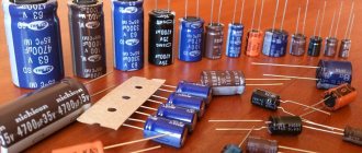
Modern tantalum capacitors are small in size and belong to chip components that are designed for mounting on a board. Otherwise, such parts are called SMD, which stands for “surface mount components.” SMD parts are convenient for automated mounting and soldering processes on printed circuit boards.
The main purpose of electrolytic polarized tantalum capacitors is to act in conjunction with a resistor to process the signal and smooth out its peaks and sharp pulses.
Capacitors are widely used in automotive, industrial, digital, and aerospace applications.
Dimensions of tantalum chip capacitor housings
The following figure can be used to determine the size based on the housing type (AV). To increase accuracy, you should pay attention to the tolerances that apply to a certain series of products.
For additional information, you need to study the accompanying documentation or find out the necessary information on the manufacturer’s official website. Universal directories may not contain all the necessary accurate data.
Separately, you need to check the installation instructions. Thus, to install compact SMD capacitors on a printed circuit board, infrared heating is used using a special camera and conventional hand soldering. In any case, the recommended temperature range should be maintained to prevent disruption of the structure of the dielectric layer and other damage.
The professional algorithm contains several stages. In the initial stage, preheating is performed at a standardized speed (3-4°C per 1 second). Next, the peak temperature and the corresponding exposure time are monitored. In different models of tantalum capacitors, the permissible maximum is set from +220°C to +260°C. Some modern household-grade soldering stations provide automatic temperature control according to user settings.
For final cleaning of the board after soldering, it is permissible to use standard products. Do not use preparations based on dichloromethane and other overly aggressive chemical compounds. They are capable of destroying the protective shell formed by the polymer compound.
Tantalum capacitors retain their original parameters unchanged for a long time if favorable storage conditions are created. In this mode, manufacturers advise maintaining the relative humidity level in the room no more than 60-65%, temperature – up to +65°C.
The possibility of unique encoding should be taken into account. Manufacturers use such solutions in the course of competition. This makes it difficult to use parts with similar technical characteristics that are created by other companies.
Design of tantalum solid capacitors
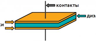
The tantalum capacitor is an electrolytic type. It consists of 4 main parts: anode, dielectric, solid electrolyte, cathode. The manufacture of a tantalum capacitor consists of a number of rather complex technological operations.
Anode manufacturing
The porous granular structure is obtained by pressing from highly purified tantalum powder. During the sintering process under high vacuum conditions at temperatures of +1300...+2000°C, a sponge structure with a developed surface area is formed from the powder. Thanks to it, high capacity is ensured in a small volume. A tantalum capacitor, with the same capacitance as an aluminum device, has a much smaller volume.
Formation of the dielectric layer
A dielectric oxide layer is grown on the surface of a tantalum pentoxide anode through an electrochemical oxidation process. The thickness of the oxide can be adjusted by changing the voltage. Typically, the thickness of the dielectric film is a fraction of a micrometer. The oxide layer has not a crystalline, but an amorphous structure, which has significant electrical resistance.
Obtaining electrolyte
The electrolyte is a solid-state semiconductor - manganese dioxide - which is obtained by heat treatment of manganese salts during the redox process. To do this, the anodic sponge layer is coated with manganese salts, and then heated to obtain manganese dioxide. The process is repeated several times until the anode is completely covered.
Formation of the cathode layer
To improve contact, the electrolyte is coated with a graphite and then a metal layer. The metal usually used is silver. The formed composite is pressed into the compound.
Design features of the device
The physicochemical properties possessed by tantalum and niobium make it possible to create an anode with a special porous structure from them. Such structures have an internal surface several tens of times larger than the external one. And this makes it possible to accumulate a significant electrical charge.
Any modern electrolytic capacitor consists of three structural elements :
- cathode and anode;
- dielectric layer;
- one of the types of electrolyte (alkali, acid, water, hard or soft substance).
The thinnest oxide film acts as a dielectric . It is produced by electrochemical corrosion by passing an electric current through the anode at the production stage.
The electrolyte is a solid substance - manganese dioxide. It has a low linear expansion coefficient and does not leak or dry out like liquid electrolytes. The inside of the cathode is made of silver to increase conductivity.
The entire internal filling is filled with a plastic-like substance with dielectric properties - a compound.
Features of tantalum capacitors
- The available capacity of these radio components is from 1 to several hundred microfarads
- Relatively low equivalent series resistance (ESR) and lowest leakage. Thanks to these properties, tantalum capacitors work successfully in high-quality audio equipment, test and measurement instruments.
- A thin oxide layer that provides high dielectric constant. The combination of a large surface area of the sponge anode with good dielectric constant provides storage of a large amount of energy.
Unlike electrolytic capacitors, tantalum capacitors explode when overcharged or breakdown. The force of the explosion depends on the size of the capacitor and can damage both adjacent elements and the circuit board.
Marking of SMD components
Due to the fact that the installation of these structures is carried out by robots (unlike electronic parts of Soviet times, which were installed by radio engineering specialists), the encodings on the housings are not always in a form that can be easily read by humans. The purpose of the marking is to help the person carrying out installation or repair work to determine what kind of model is in front of him. The robot is indifferent to the markings, its incomprehensibility does not affect the quality of the assembly, however, when repairing a board, an amateur radio technician sometimes has to work with reference books to figure out what part it is.
We advise you to study What is better: a convector or a fan heater
Breakdowns of tantalum capacitors
When using these effective, but somewhat capricious devices, it is necessary to monitor the occurrence of a failure condition, since they have been known to catch fire when they fail. Failures are due to the fact that, if used incorrectly, tantalum pentoxide changes its amorphous structure to a crystalline one, that is, it turns from a dielectric into a conductor. A change in structures can occur due to too high inrush current. Dielectric breakdown causes an increase in leakage currents, which in turn lead to breakdown of the capacitor itself.
The cause of troubles associated with the operation of tantalum capacitors may be manganese dioxide. The oxygen present in this compound causes the appearance of local fires. Breakdowns with fire are typical for older models. New technologies make it possible to obtain more reliable products.
Breakdowns that occur at high temperatures and voltages can cause an avalanche effect. In this case, the damage often extends over most or all of the device. If the area of crystallized tantalum pentoxide is small, then a self-healing effect often occurs. It is possible due to the transformations occurring in the electrolyte in the event of dielectric breakdown. As a result of all transformations, the crystallized conductor site is surrounded by manganese oxide, which completely neutralizes its conductivity.
Other defects of tantalum capacitors
In addition to breakdown, other defects occur in the capacitor as a result of incorrect production technology and violation of transportation and storage rules:
The first type of such defects can appear on the grown dielectric as a result of its sharp impact on a hard surface. The second is during the formation of an electrolyte layer due to the combined action of thermal shock and internal gas pressure in the pores.
If the production technology is violated, foreign substances may appear on the tantalum surface - carbon, iron, calcium, which lead to unevenness of the dielectric layer.
that appeared during the manufacture of the device. Crystallization can occur due to a discrepancy between the electrolyte composition and the technological requirements and incorrect temperature conditions of the process.
Tantalum polymer capacitors
Most of the problems characteristic of tantalum capacitors have been solved in tantalum-polymer analogues. Tantalum polymer capacitors use a conductive polymer instead of manganese dioxide as the electrolyte. It gives minimal ESR, which allows much higher currents to pass compared to tantalum predecessors. Tantalum-polymer devices are successfully used as smoothing capacitors in power supplies and voltage converters.
The conductive polymer provides low sensitivity to current pulses, resistance to external factors, lack of structure degradation, and a longer service life. The high stability of capacitance over a wide range of frequencies and temperatures allows the use of tantalum-polymer devices in industrial, telecommunications and automotive electronics and other areas characterized by fluctuations in operating temperatures.
Varieties
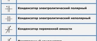
Due to their ability to quickly accumulate and release electrical energy, capacitors have found wide application as energy storage devices in various filters and in pulsed devices. Capacitors differ according to the following characteristics: the nature of the change in capacitance, the method of protection from external influencing factors, purpose, installation method and type of dielectric.
It will be interesting➡ What is the difference between a starting capacitor and a working one?
According to the nature of the change in capacitance, they are divided into capacitors of constant capacitance, tuned capacitors and capacitors of variable capacitance. The capacitance of permanent capacitors is fixed, i.e. not adjustable during operation.
Types of capacitors.
The capacity of adjusted capacitors changes during one-time or periodic adjustment and does not change during the operation of the equipment. Tuned capacitors are used for tuning and leveling the initial capacitances of mating circuits, for periodic tuning and adjustment of circuits where a slight change in capacitance is required. Variable capacitors allow the capacitance to change during the operation of the equipment.
The capacitance can be controlled mechanically, electrically (variconds) and temperature (thermal capacitors). Such capacitors are used for smooth adjustment of oscillatory circuits and in automation circuits.
According to the method of protection from external influencing factors, capacitors are made unprotected (allow operation at high humidity only as part of sealed equipment), protected.
Uninsulated, coated or uncoated (do not allow the chassis to touch); insulated (with insulating coating), compacted organic materials; sealed using ceramic and metal cases or glass flasks, which eliminates the interaction of the internal space with the environment.
Depending on the installation method, capacitors are made for printed and mounted mounting, as well as for use as part of micromodules and microcircuits. Most oxide, pass-through and support capacitors have one of the plates connected to the body, which serves as the second terminal. According to their purpose, capacitors are divided into general purpose (usually low-voltage, without special requirements) and special. The use of capacitors in specific circuits of equipment (low-voltage, high-voltage, low-frequency, high-frequency, pulse, starting, polar, non-polar, interference suppression, dosimetric, nonlinear, etc.) depends on the type of dielectric used in them. Based on the type of dielectric, capacitors are divided into groups: with organic, inorganic, oxide and gaseous dielectric.
Types of capacitors.
Organic dielectric capacitors
Organic dielectric capacitors are manufactured by winding capacitor paper, films, or a combination thereof with metallized or foil electrodes. They are conventionally divided into low-voltage (up to 1000...1600 V, and for oxide ones up to 600 V) or high-voltage (over 1600 V).
In turn, low-voltage capacitors are divided into low-frequency with an operating frequency of up to 105 Hz (based on polar and weakly polar organic films: paper, metal-paper, polyethylene terephthalate, combined, lacquer film, polycarbonate and polypropylene) and high-frequency with operating frequencies of up to 107 Hz (on based on non-polar organic films: polystyrene, fluoroplastic and some polypropylene).
High-voltage capacitors are divided into high-voltage direct voltage (paper, polystyrene, fluoroplastic, lavsan and combined are used as dielectrics) and high-voltage pulsed (based on paper and combined dielectrics).
Combined capacitors have increased electrical strength compared to paper ones. High-voltage pulse capacitors must pass large currents without distortion, i.e. must have low self-inductance.
Dosimetric capacitors (usually fluoroplastic) operate in circuits with low current loads, have high insulation resistances and time constants. Interference-suppressing capacitors (usually paper, combined and lavsan) are designed to reduce electromagnetic interference, have high insulation resistance, low self-inductance, which increases the band suppressed frequencies.
Film capacitors
They are produced on the basis of synthetic films with a thickness of 1.4...30 microns. Depending on the dielectric used, they are divided into groups of non-polar films (polystyrene, fluoroplastic, polypropylene), polar films (polyethylene terephthalate, i.e. lavsan polycarbonate), combined (foam and paper) and varnish films. Each class of capacitors has a specific set of properties, and in general, film capacitors cover a wide range of requirements of modern technology.
It will be interesting➡ What is a variable capacitor
Film condensates are distinguished by higher electrical and operational characteristics and lower manufacturing complexity compared to paper ones, so their production is constantly growing. Capacitors are available with foil and metallized plates. Foil capacitors are distinguished by higher and more stable electrical characteristics. Capacitors with metal plates differ from foil ones by improved specific characteristics. This is achieved due to the self-healing property inherent in such capacitors, which makes it possible to increase the operating electric field strengths.
Related material: How to check a varistor with a multimeter.
The areas of application of fluoroplastic and polystyrene capacitors are almost the same. Fluoroplastic capacitors are used at elevated temperatures and more stringent requirements for electrical parameters.
Capacitors with inorganic dielectric
They use ceramics, glass, glass enamel, glass ceramics or mica as a dielectric. Capacitors with such dielectrics are divided into low-voltage, high-voltage and noise-suppressing. Low-voltage capacitors, in turn, are divided into low-frequency and high-frequency (with frequencies up to hundreds of megahertz or more) and are intended: for use in resonant circuits and circuits where low losses and high capacitance stability are required (high-frequency!. In blocking and decoupling filter circuits , where low losses and capacitance stability are not of particular importance, ceramic capacitors with large dielectric losses (low frequency) are used.
High-frequency capacitors include mica, glass-enamel, glass-ceramic and ceramic; to low-frequency - glass-ceramic and ceramic. High-voltage capacitors are made with a ceramic dielectric with a high dielectric constant and are also divided into low-frequency and high-frequency. They have a design and terminals designed to carry high currents.
Interference-suppressing capacitors are divided into support capacitors with a disk or tubular type design (one of their terminals is a support metal plate with a threaded connection) and feed-through coaxial and non-coaxial); designed to suppress industrial, atmospheric and high-frequency interference. Ceramic capacitors are the most widely used in electronic equipment. The main advantages of ceramic capacitors include:
- the ability to implement a wide scale of capacitances from fractions of a picofarad to units and tens of microfarads;
- the ability to implement a given temperature coefficient of capacity (TKE,;
- high resistance to external factors (temperature, air humidity, etc.) and high reliability;
- the possibility of using ceramic crystals together with microcircuits or as part of microcircuits;
- simplicity of technology, making mass-produced ceramic capacitors the cheapest.
Ceramic capacitors can be divided into two groups: constant capacitance, among which there are low-voltage (Unom < 1600 V) and high-voltage (Unom ≥ 1600 V), and tuned ones. Based on their basic designs, low-voltage ceramic capacitors can be divided into:
- tubular (KT-1, 2, 3; K10-38);
- disk (KD-1, 2; K10-i9; K10-29; K10-78);
- plate (K10-7V);
- semiconductor (with barrier layer K10U-5)
- monolithic (K10-17, K10-27, K10-42; K10-43; K10-47; K10-49, K10-50, K10-60, K22-5);
- special – walk-through and support (KTP. K10P-4, KO, KDO).
Single-layer capacitors of tubular, disk and plate designs are the most common. They are produced in a range of capacitances from 0.47 pF to 0.063 μF and voltages up to 800 V. A variety of design options for single-layer capacitors and a wide range of their sizes allow the consumer to choose the best option based on the combination of parameters and cost of products.
Various capacitors.
Main parameters of tantalum capacitors
To determine a safe operating mode, it is necessary to calculate the levels of permitted current and voltage values. For calculations, you need to know the following parameters of tantalum capacitors, which are reflected in the documentation:
- Nominal capacity.
These devices have high specific capacitance, which can be thousands of microfarads. - Rated voltage.
Modern models of these devices are mostly designed for voltages up to 75 V. Moreover, for normal operation in an electrical circuit, the part must be used at voltages that are less than the nominal one. Operating tantalum capacitors at voltages up to 50% of the rated voltage reduces the failure rate to 5%. - Impedance (total resistance).
Contains inductive component, parallel resistance, series equivalent resistance (ESR). - Maximum power dissipation.
When AC voltage is applied to a tantalum device, heat is generated. The permissible increase in the temperature of the capacitor due to the released power is established experimentally.
Tantalum capacitors › K52-9, 11
Purchase price per kg 1755 UAH. and 4758.88 in rubles.
Purpose, brief description of tantalum capacitors K52-9.11 Tantalum capacitors K52-9.11 are liquid, volumetric porous, polar, sealed tantalum capacitors in a metal case. They have the shape of cylinders with leads on both sides and corresponding markings. Used tantalum capacitors are valued because they contain the expensive metal tantalum and are recyclable.
Technical characteristics of tantalum capacitors K52-9: weight: 3.5-18 g tantalum content: 0.49 g/piece. rated capacitance: 1.5-1000uF rated voltage: 6.3-125V
Features of board design and installation of tantalum capacitors
Almost all printed circuit board materials are suitable for these devices - FR4, FR5, G10, fluoroplastic, aluminum. The shape, size of the seat and installation method are specified by the manufacturers of the parts. The recommended installation parameters can be changed by a specialist who has sufficient knowledge and skills to correctly adjust the soldering temperature.
Before installation, solder paste is applied to the board. Layer thickness – 0.178+/-0.025 mm. In order for the flux contained in the paste to effectively dissolve oxides from the contact points, the optimal soldering temperature regime is selected. This is usually done empirically.
Mounting to the board is done manually or using any type of automated equipment used today. Soldering is done: manually, by wave method, in infrared or convection ovens. Temperature conditions for preheating and soldering are usually provided by manufacturers of specific products.
Types of markings
At the moment, manufacturers use several types, which can be located on the body either individually or interchangeably. All values below will be purely theoretical, provided for illustrative purposes.
- The simplest type of marking - no codes or table substitutions, the capacity is directly written on the body, which immediately provides the end user with real parameters without unnecessary movements. And this method would be used everywhere, if not for its bulkiness - it will be possible to completely write the container only on fairly large products, otherwise it will be impossible to see the inscription even with a magnifying glass. For example: writing 100 µF±6% means that this capacitor has a capacitance of 100 microfarads with a damping of 6% of the total capacitance, which is equal to a value of 94-106 microfarads. It is also possible to use markings of the form 100 µF +8%/-10%, which means unequal damping equal to 90–108 microfarads. This is the simplest and most understandable method, however, such marking is very cumbersome, so it is used on large and very capacitive capacitors.
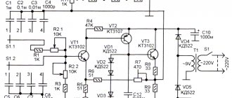
- Digital marking of capacitors (as well as numerical and alphabetic markings) is used in cases where the small area of the product does not allow a detailed record of the capacitance to be placed. Therefore, certain values are replaced with ordinary numbers and Latin letters, which are deciphered one by one to obtain complete information.
Everything is very simple - if only numbers are used (and on such products there are usually three of them), then you need to decipher them as follows:
- the first two digits indicate the first two digits of the capacity;
- the third digit indicates the number of zeros that must be added after the first two digits;
- such capacitors are always measured in picofarads.
Let's take for example the first option from the picture above with the entry 104. We leave the first two digits as 10. To them we add the number of zeros indicated by the third digit, that is, 4. We get a value of 100,000 picofarads. We return to the table at the beginning of the article, reduce the number of zeros and get an acceptable value of 100 microfarads.
If one or two digits are used, they remain that way. For example, the notations 5 and 15 represent 5 and 15 picofarads, respectively. Marking .55 is equal to 0.55 microfarads.
An interesting notation is made using letters either instead of a dot or as another quantity. For example, 8n2 means 8.2 nanofarads, while n82 means 0.82 nanofarads. For a certain class of capacitors, an additional code marking may be added at the end, for example, 100V.
- Labeling of ceramic capacitors using a numerical and alphabetic method is the standard for these products. Here, exactly the same encryption algorithms are used, and the inscriptions themselves are physically applied by the manufacturer to the ceramic surface.
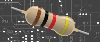
- An outdated, but still used option is color indication. It was used in Soviet production to simplify the reading of markings even on very small products. The downside is that it is quite problematic to remember such a table right away, so it is advisable to have it on hand, at least at first. The colors are applied to the capacitors, where the marking is done in the form of monotonous stripes. Read as follows: the first two colors indicate the capacitance in picofarads;
- the third color shows the number of zeros that need to be added;
- the fourth and fifth colors respectively show the possible tolerance and nominal voltage supplied to the product.
- Marking of imported capacitors is carried out in similar ways, only the Latin alphabet can be used instead of Cyrillic. For example, on domestic versions there may be 5mk1, which means 5.1 microfarads. Whereas on imported ones this value will look like 5µ If the entry is completely incomprehensible, then you can contact the official manufacturer for clarification; most likely, the website has tables or a program that decipher its markings. However, this occurs only in exceptional cases and is rarely encountered.
Marking of tantalum capacitors
The markings of capacitors indicate standard parameters: capacitance, rated voltage, polarity. On cases of types B, C, D, E, V, all parameters are displayed, and on case of type A, instead of the voltage rating, its letter code is indicated. The marking may indicate additional information - the manufacturer’s logo, production date code, etc.
Voltage Code Table for Type A Enclosures
Rated voltage
| Code | Rated voltage | Code | |
| 4,0 | G | 20 | D |
| 6,3 | J | 25 | E |
| 10 | A | 35 | V |
| 16 | C | 50 | T |
Types of tantalum capacitor housings and their sizes
Low ESR Tantalum Capacitors
Reducing the ESR value of tantalum capacitors has been the goal of intensive work on their design. The main cathode material was initially powdered manganese dioxide. The cathode material and the process of its formation have a significant impact on the size of the ESR. Significant reduction in ESR was achieved by replacing the MnO2 cathode with a conductive polymer and changing the metal lead frame material from ferronickel alloys to copper.
Copper material with higher lead frame conductivity also reduces ESR significantly. The traditional frame material is iron-nickel alloy (alloy 42). Its advantage is a low coefficient of thermal expansion, low cost and ease of processing.
Significant advances in the production of copper lead frames have facilitated their use in tantalum capacitors. The electrical conductivity of copper is approximately 100 times higher than that of alloy 42, which significantly contributes to the reduction of ESR. For example, the ESR of a Vishay 100uF, 6.3V tantalum polymer capacitor in an A package (EIA 3216) with a traditional lead faceplate is 70mOhm.
Storage Features
Tantalum capacitors are able to maintain performance characteristics for a long time. If the required conditions are observed (temperature up to +40°, relative humidity 60%), the capacitor loses its ability to be soldered during long-term storage, while maintaining other performance characteristics.
General recommendations for extending the service life of a tantalum capacitor and increasing the safety of its operation:
- Compliance with technical process requirements;
- Multi-stage product quality control;
- Compliance with storage conditions;
- Fulfilling the requirements for organizing a workplace for mounting devices on a board;
- Compliance with the recommended soldering temperature conditions;
- Correct selection of safe operating modes;
- Compliance with operating requirements.
Dimensions of tantalum chip capacitor housings
The following figure can be used to determine the size based on the housing type (AV). To increase accuracy, you should pay attention to the tolerances that apply to a certain series of products.
For additional information, you need to study the accompanying documentation or find out the necessary information on the manufacturer’s official website. Universal directories may not contain all the necessary accurate data.
Separately, you need to check the installation instructions. Thus, to install compact SMD capacitors on a printed circuit board, infrared heating is used using a special camera and conventional hand soldering. In any case, the recommended temperature range should be maintained to prevent disruption of the structure of the dielectric layer and other damage.
The professional algorithm contains several stages. In the initial stage, preheating is performed at a standardized speed (3-4°C per 1 second). Next, the peak temperature and the corresponding exposure time are monitored. In different models of tantalum capacitors, the permissible maximum is set from +220°C to +260°C. Some modern household-grade soldering stations provide automatic temperature control according to user settings.
For final cleaning of the board after soldering, it is permissible to use standard products. Do not use preparations based on dichloromethane and other overly aggressive chemical compounds. They are capable of destroying the protective shell formed by the polymer compound.
Tantalum capacitors retain their original parameters unchanged for a long time if favorable storage conditions are created. In this mode, manufacturers advise maintaining the relative humidity level in the room no more than 60-65%, temperature – up to +65°C.
The possibility of unique encoding should be taken into account. Manufacturers use such solutions in the course of competition. This makes it difficult to use parts with similar technical characteristics that are created by other companies.