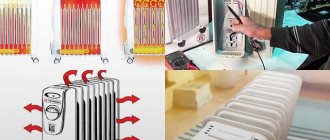
Measurement speed
The performance is determined by the ability of the primary converter to quickly respond to temperature surges and the subsequent flow of input signals from the measuring device.
Factors that increase performance:
- Correct installation and calculation of the length of the primary converter;
- When using a converter with a protective sleeve, it is necessary to reduce the mass of the assembly by selecting a smaller diameter of the sleeves;
- Minimizing the air gap between the primary converter and the protective sleeve;
- Using a spring-loaded primary converter and filling the voids in the sleeve with a heat-conducting filler;
- A fast moving or denser medium (liquid).
How to remove a thermocouple from a gas water heater
In order to be able to quickly repair a geyser with my own hands and always have warm water, taking into account the experience of long-term operation of gas water heaters of different models, I always have a set of spare parts on hand. Rubber gaskets, tubes, thermal relay and thermocouple included. Therefore, within half an hour the thermocouple was replaced with a new one, and the column again began to properly heat the water.
The thermocouple is secured to the left on the common bar with the igniter and spark plugs using a nut. Before unscrewing the nut, you need to slightly unscrew the left self-tapping screw holding the bar so that it does not interfere with the wrench turning.
Next, use an open-end wrench to unscrew the nut by rotating counterclockwise until it completely comes off the thread on the thermocouple body. After this, the thermocouple will easily come down from the bar.
In the next step, you need to use an open-end wrench to unscrew the contact screw from the gas-water regulating unit. The screw is located on the opposite side of the gas control knob.
All that remains is to remove two terminals from the thermal protection relay, and the thermocouple, complete with wires, will be removed from the gas water heater.
Installation of a new thermocouple is carried out in the reverse order, and it is desirable that the current-carrying wires do not touch either the internal metal parts of the gas column or the casing after its installation.
Thermocouples: structure and principle of operation in simple language, types
In process automation, it is very often necessary to take indicators of temperature changes in order to load them into control systems for the purpose of further processing.
This requires high-precision, low-inertia sensors that can withstand high temperature loads within a certain measurement range.
Thermocouples are widely used as thermoelectric converters - differential devices that convert thermal energy into electrical energy.
In particular, the control automation of gas boilers and other heating systems is triggered by an electrical signal coming from a thermocouple-based sensor.
The sensor designs provide the necessary measurement accuracy in the selected temperature range.
Device and principle of operation
The thermocouple is structurally composed of two wires, each of which is made of different alloys. The ends of these conductors form a contact (hot junction) made by twisting, using a narrow weld or butt welding.
The free ends of the thermocouple are closed using compensation wires to the contacts of the measuring device or connected to an automatic control device. At the connection points another so-called cold junction is formed.
The device is shown schematically in Figure 1.
Rice. 1. Scheme of the thermocouple structure
The hot junction area is highlighted in red, the cold junction is highlighted in blue.
The electrodes consist of different metals (metal A and metal B), which are painted in different colors in the diagram. In order to protect thermoelectrodes from aggressive hot environments, they are placed in a sealed capsule filled with an inert gas or liquid. Sometimes ceramic beads are placed on the electrodes, as shown in Fig. 2).
Rice. 2. Thermocouple with ceramic beads
The operating principle is based on the thermoelectric effect. When a circuit is closed, for example with a millivoltmeter (see Fig. 3), a thermo-emf occurs at the junction points.
But if the electrode contacts are at the same temperature, then these EMFs compensate each other and no current occurs.
However, if you heat the hot solder joint with a torch, then, according to the Seebeck effect, a potential difference will arise, supporting the existence of an electric current in the circuit.
Rice. 3. Measuring voltage on TC wires
It is noteworthy that the voltage at the cold ends of the electrodes depends proportionally on the temperature in the hot junction area.
In other words, in a certain temperature range we observe a linear thermoelectric characteristic that displays the dependence of the voltage on the magnitude of the temperature difference between the hot and cold junction points.
Strictly speaking, we can talk about linearity of indicators only in the case when the temperature in the cold junction region is constant. This should be taken into account when calibrating thermocouples.
If the temperature changes at the cold ends of the electrodes, the measurement error can be quite significant.
In cases where it is necessary to achieve high accuracy of indicators, the cold junctions of the measuring transducers are even placed in special chambers in which the temperature environment is maintained at the same level by special electronic devices using data from a resistance thermometer (the diagram is shown in Fig. 4). With this approach, it is possible to achieve measurement accuracy with an error of up to ± 0.01 °C. True, such high precision is needed only in a few technological processes. In some cases, the requirements are not so stringent and the error can be an order of magnitude lower.
Rice. 4. Solving the issue of accuracy of thermocouple readings
The error is affected not only by temperature changes in the environment surrounding the cold junction. The accuracy of the readings depends on the type of construction, wiring diagram, and some other parameters.
Types of thermocouples and their characteristics
Different alloys used to make thermocouples have different thermo-EMF coefficients. Depending on what metals the thermoelectrodes are made of, the following main types of thermocouples are distinguished:
- TPP13 – platinum-rhodium-platinum (type R);
- TPP10 – platinum-rhodium-platinum (type S);
- TPR – platinum-rhodium-platinum-rhodium (type B);
- TFA – iron-constantan (type J);
- TMKn – copper-constantan (type T);
- TNN – nichrosil-nisil (type N);
- THA – chromel-alumel (type K);
- THCn – chromel-constantan (type E);
- THC – chromel-copel (type L);
- TMK – copper-copel (type M);
- TSS – sil-silin (type I);
- TVR – tungsten rhenium (types A-1 – A-3).
About thermocouples: what they are, principle of operation, connection, application
In process automation, it is very often necessary to take indicators of temperature changes in order to load them into control systems for the purpose of further processing.
This requires high-precision, low-inertia sensors that can withstand high temperature loads within a certain measurement range. Thermocouples are widely used as thermoelectric converters - differential devices that convert thermal energy into electrical energy. The devices are also a simple and convenient temperature sensor for a thermoelectric thermometer designed to make accurate measurements over fairly wide temperature ranges. In particular, the control automation of gas boilers and other heating systems is triggered by an electrical signal coming from a thermocouple-based sensor. The sensor designs provide the necessary measurement accuracy in the selected temperature range.
How to lay nanoisol
Installation of the material is carried out strictly according to standardized rules. In order to protect the insulation, the vapor barrier material is placed in the interior of the room between the sheathing and the thermal insulation layer.
How and in what cases can it be restored?
The thermocouple is designed in such a way that any damage or contamination can reduce the voltage it produces below a critical level. A very common cause of malfunction is carbon deposits or a layer of soot on its working (heated) part. To restore the thermocouple, just clean it with a soft brush or cotton wool and alcohol, while avoiding scratches and other damage. After cleaning, it is worth checking the voltage again following the instructions above.
Oxidized contacts are also a common cause; they can be carefully treated with sandpaper. If the thermocouple has a deep black dent or hole due to burning, it is guaranteed to need to be replaced.
Thermocouple connection diagram
The most common ways to connect measuring instruments to thermocouples are the so-called simple method, as well as a differentiated one. The essence of the first method is as follows: a device (potentiometer or galvanometer) is directly connected to two conductors. With the differentiated method, not just one, but both ends of the conductors are soldered, while one of the electrodes is “broken” by the measuring device.
It is impossible not to mention the so-called remote method of connecting a thermocouple. The operating principle remains unchanged. The only difference is that extension wires are added to the circuit. For these purposes, a regular copper cord will not be suitable, since the compensation wires must be made of the same materials as the thermocouple conductors.
Compensation wires
Thermocouples include compensation wires that look like extension cords to connect devices to the measuring instrument. If you arrange the free ends in the head of the thermoelectric converter, then practically its connection cannot be made, since the device operates at very high temperatures.
In addition, the device that receives data cannot always be located close to the sensors. Therefore, it is often necessary to connect the measuring instrument at a distance from the location where the sensors are installed. This problem is successfully solved by compensation wires. They are usually made from the same material as thermoelectric sensors.
Extension wires are found in areas with lower temperatures, so it is possible to make them from cheaper material. When using compensation wires, it is necessary to take into account the possibility of the appearance of parasitic electromotive forces. The wires must ensure that the free ends are directed away from the thermocouple to an area with a low and constant temperature.
Thermocouple junction
Most thermocouples are designed with only one junction. However, when a thermocouple is connected to an electrical circuit, another junction may form at its connection points.
Thermocouple circuit
The circuit shown in the figure consists of three wires labeled A, B, and C. The wires are twisted together and labeled D and E. A junction is an additional junction that is formed when a thermocouple is connected to the circuit. This junction is called the free (cold) junction of the thermocouple. Junction E is the working (hot) junction. There is a measuring device in the circuit that measures the difference in voltage values at two junctions.
The two junctions are connected in such a way that their voltage opposes each other. Thus, the same voltage value is generated at both junctions and the device readings will be zero. Since there is a directly proportional relationship between temperature and the amount of voltage generated by a thermocouple junction, two junctions will generate the same voltage values when the temperature across them is the same.
Effect of heating one thermocouple junction
When the thermocouple junction heats up, the voltage increases in direct proportion. The flow of electrons from the heated junction flows through the other junction, through the measuring instrument and back to the hot junction. The device shows the voltage difference between two junctions. Voltage difference between two junctions. The voltage difference shown by the meter is converted into temperature readings, either using a table or directly displayed on a scale that is calibrated in degrees.
Thermocouple cold junction
The cold junction is often the point where the free ends of the thermocouple wires are connected to the meter.
Since the thermocouple circuit meter is actually measuring the voltage difference between the two junctions, the cold junction voltage must be kept as constant as possible. By maintaining the voltage at the cold junction at a constant level, we thereby ensure that a deviation in the readings of the measuring device indicates a change in the temperature at the working junction.
If the temperature around the cold junction changes, the voltage across the cold junction will also change. As a result, the voltage at the cold junction will change. And as a result, the difference in voltage at the two junctions will also change, which will ultimately lead to inaccurate temperature readings.
In order to keep the cold junction temperature constant, many thermocouples use compensating resistors. The resistor is in the same location as the cold junction, so the temperature affects the junction and the resistor at the same time.
Thermocouple circuit with compensating resistor
Working junction of thermocouple (hot)
A service junction is a junction that is exposed to the process whose temperature is being measured. Due to the fact that the voltage generated by a thermocouple is directly proportional to its temperature, when the working junction is heated, it generates more voltage, and when cooled, less.
Working junction and cold junction
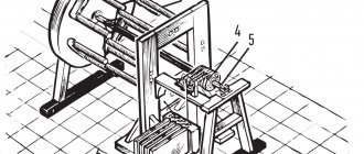
Method of attaching a thermocouple to a metal product
The invention relates to contact measurement of temperatures of metal products. Essence: a groove or hole is formed in the product, no less than four diameters of the installed thermocouple. Install the thermocouple in the groove or hole. The thermocouple is molded with a mixture composition, including kaolin clay, P-0.66 flux and liquid glass, in the following ratio, wt. %: kaolin clay 92-97; flux P-0.66 2-5; liquid glass the rest. Technical result: providing the possibility of multiple attachment of a thermocouple to a product without destroying the working junction, simplifying the hardware during the attachment process and ensuring repeatable measurement accuracy. 1 ill., 1 tab.
The invention relates to methods for contact measurement of the temperature of samples (products), workpieces made of metals and alloys under conditions of elevated temperatures and long periods of time.
The conditions that must be observed when measuring the temperature of products with thermocouples during such tests are characterized by the following requirements:
— maximum thermal contact with the sample;
— reliable fastening to the sample;
— repeated use of the working junction of the same thermocouple;
— low inertia of the thermocouple.
Currently, the required conditions for attaching thermocouples are achieved in two ways. The first is mechanical pressing of the thermocouple to the surface of the sample (author of the St. USSR N 49379, class G01K 7/02) or gluing the thermocouple to the sample (author of the St. USSR N 123215, class H01L 35/34). Such methods do not provide sufficient accuracy and repeatability of temperature measurement results when it rapidly increases due to the presence of thermal resistance of the adhesive film at the point of contact between the thermocouple and the sample. The magnitude of such thermal resistance is large and reduces the accuracy of temperature measurement by several times, and the repeatability of measurements can be reduced by tens of times.
The second way is to make a hole in the sample (author of the St. USSR N 180382, class G01K 7/02), pressing the thermocouple into the test object (author of the St. USSR N 110933, class 21 in 27/03), caulking and filling holes with amalgam (author of St. USSR N 370480, class G01K 7/02). Such methods, while creating mechanical strength for attaching the thermocouple to the sample, do not provide the possibility of reusing the same working junction of the thermocouple when measuring temperature on a series of samples or products, which leads to a decrease in the repeatability of the measurement results.
The closest to the invention in technical essence is the method (ed. St. USSR N 150268, class G01K 7/02), which consists of placing thermocouples or thermoelements in the body of the test object. To do this, thermocouples are embedded in the surface of metal products by filling the groove at the place of their installation with molten metal (for example, copper) under a deep vacuum.
The disadvantage of this method is the inability to reuse the working junction (and some part of the thermocouple) to measure temperature on subsequent products, which significantly increases the consumption of thermocouples and the cost of measurements when using thermocouples made of expensive metals, for example type TPR type B), does not ensure accuracy and repeatability results, in addition, the impossibility of obtaining a series of working junctions of thermocouples with the same characteristics, due to foreign impurities entering the working junction during the welding process.
Filling a groove with molten metal and installing a thermocouple on a product under deep vacuum requires complex hardware when attaching thermocouples to products.
The problem solved by the present invention is to reduce the costs of implementing the method.
The technical essence lies in the possibility of reusing the working junction of a thermocouple with the same characteristics when measuring the temperature of heated products, by attaching it to them with a special mixture composition, simplifying the hardware design in the process of its attachment and repeatability of measurement accuracy.
This problem is solved in a method for attaching a thermocouple to a metal product, which includes forming a groove or hole in the product, installing a thermocouple in it, molding it, the groove or hole is formed with a size of at least four diameters of the installed thermocouple, and the molding of the thermocouple is carried out with a mixture containing kaolin clay, flux P-0.66 and liquid glass, at the following ratio, wt., %:
| kaolin clay | 92-97 |
| flux P-0.66 | 2-5 |
| liquid glass | rest |
The sequence of performing these operations makes it possible to obtain a sufficiently high mechanical strength after solidification of the liquid glass in the mixture and will ensure dense and durable contact between the working junction and the surface of the test sample or product. After carrying out measurements (up to 40 cycles, after four reinstallations from one sample to the next), the place where the thermocouple is attached is quite easily destroyed (by tapping the sample on a metal object or by heating the sample to a temperature of 1200-1300°C (where the fastening material softens).
As an example of attaching a thermocouple with a mixture composition to a sample, we selected 30MnV5 steel according to the EN 10083-3 standard, which is used for the manufacture of working parts of agricultural machines: pointed shares, discs, ploughshares, etc.
The method was carried out as follows.
Samples measuring 15*30*8 mm in the amount of 30 pieces were cut from rolled steel 30MnV5, which were divided into 5 batches of 6 pieces each. in each.
In 15 samples, a through groove 10 mm long and 2.5-3.0 mm wide was cut, and in the rest, holes were drilled with a depth of 10 mm and a diameter of 2.5-3.0 mm.
The working junction of the thermocouple was formed by contact welding.
The diameter of the chromel-alumelium thermocouple was 0.8 mm.
Then the mixture was prepared to attach the thermocouple to the sample.
The prepared groove or hole with a thermocouple was filled with the compositions given in the table.
The prepared samples were placed in an inductor connected to a high-frequency inverter ELSIT-70/100 and heated six times by high-frequency heating from 20 to 1250°C, then the mount was destroyed and a thermocouple with a working junction was installed on subsequent samples with single heating (in the amount of 6 pieces).
When testing samples of temperature measurement values up to temperatures of 300-420°C, the error did not exceed 1.5-3.0%, and after 780-1250°C and installing a thermocouple on subsequent samples, it did not exceed 3.7% (on six samples ).
In fig. 1 - shows a sample with a fixed thermocouple: 1 - sample made of 30MnV5 steel; 2 - thermocouple; 3 - fastening composition of the mixture; 4 - slot.
It was experimentally established that the maximum effect from attaching a thermocouple to the samples is achieved when the clay content is from 92 to 97%, and the flux content is from 2 to 5% and the rest is liquid glass, the density of which was 1.5 g/cm3 (composition of mixtures No. 1-3) .
In its raw state, the mechanical strength of the fastening mixture is provided by liquid glass.
When borax and boric anhydride are heated above 790°C, a glassy mass is formed that interacts with the metal surface; oxides such as wustite are formed, the crystal lattice of which is completed by α-iron, which ensures the mechanical strength of the mixture with a thermocouple and with a metal surface
When the content of kaolin clay is less than the declared one, for example: 90%, the strength does not increase significantly, but the consumption of the expensive binding material flux P-0.66 (mixture composition No. 4) increases, and with an increase in the binding component, for example 99%, the mechanical strength is low, the thermocouple does not fixed (mixture composition No. 5) in a hole or groove.
The amount of binder (flux P-0.66) introduced into the mixture, ensuring optimal strength of attachment of the thermocouple to the surface, is the composition of the mixture No. 1-3 given in the table.
By increasing the amount of binder (flux P-0.66) to a more optimal level, for example 9%, the strength of the fastening mixture to the inner surface of the sample increases significantly, which significantly complicates the subsequent removal of the thermocouple from the groove or hole (mixture composition No. 4).
If the binder content is less than the declared one (2%), for example 1% (mixture composition No. 5), the mechanical strength of the fastening mixture is significantly reduced and it does not provide strong attachment of the thermocouple to the sample or product, which significantly affects the accuracy of temperature measurement.
If the groove or hole diameter is reduced to less than four diameters of the thermocouple, the mechanical strength of the fastening mixture increases significantly and removal of the working junction and thermocouple becomes difficult and even leads to rupture of the thermocouple.
In the case of an increase in the width of the groove or the diameter of the hole by more than four times, the degree of extraction is simplified, conditions are created for the mechanical destruction of the fastening mixture, for example with a thin drill, but the accuracy of measurements is reduced, since the effect of a walled-up thermocouple in the heat-insulating object is observed, the heating rate decreases. sample cooling decreases.
Thus, a method is proposed for repeatedly attaching a thermocouple to a sample or part without destroying the working junction and using complex hardware, which significantly increases the repeatability of the results obtained.
A method of attaching a thermocouple to a metal product, including forming a groove or hole in the product, installing a thermocouple in it, molding it, characterized in that the groove or hole is formed with a size of at least four diameters of the installed thermocouple, and the molding of the thermocouple is carried out with a mixture containing kaolin clay, flux P-0.66 and liquid glass, at the following ratio, wt., %:
| kaolin clay | 92-97 |
| flux P-0.66 | 2-5 |
| liquid glass | rest |
What is it and what is it for?
Purchasing a thermocouple for a gas stove is a concern for the safety of your family.
Essentially, it is a sensor that records temperature. But not the environment, but the flame of the stove burner. However, the developers did not try to monitor changes in the temperature of the fire, but only its presence. The fire is on, the sensor is heated, everything works fine. The fire goes out, the sensor has cooled down, the gas is turned off.
Buying a gas stove with a thermocouple is not much more expensive than without it, but the prevention of gas leaks is guaranteed.
Everything is simple, effective and inexpensive. The presence of the option slightly affects the price of the model. And the safety of such a stove increases.
In general terms, a temperature sensor is a small cylinder made of two metals welded together. Wires go from it to the solenoid valve. It is he who controls the gas supply. The operation of the system is based on physical laws, which many forgot about immediately after school.
Let's repeat physics
The thermocouple is based on the laws of physics: a closed circuit of metal conductors produces an electric current when heated.
The first effect that formed the basis of a thermocouple was discovered by the German physicist T. Seebeck. In his experiments, he established that a closed circuit of two conductors of different metals forms an electric current when heated. In this case, the more the soldering of conductors is heated, the greater the current appears.
The German scientist T. Seebeck was the first to discover the physical phenomenon on which the action of a thermocouple is based.
One contact of the circuit becomes hot and is called “hot”. The other, “cold” one should be at a lower temperature. The temperature reading is taken from it. Since the dependence of the resulting current on the heating temperature is strictly linear.
Thermocouple markings
Before purchasing a device, it is important to understand the product labeling in order to choose the appropriate option.
Pairs of metals whose use is most effective were established experimentally. Depending on the metals used, the device has its own marking. Knowing it and the characteristics of the resulting junctions, you can choose a sensor suitable for your needs.
The following types are distinguished:
- K (ТХА/ХА) – nickel with chromium or alumel. Common, accurate and inexpensive with an accuracy of +/- 1.10 C and a range from -270 to 12600 C.
- L (THC) – chromel with copel. The main feature is durability.
- J – iron with constantan. The second most popular with a range from -210 to 7600C, is not durable.
- T – copper with constantan. A highly specialized device for particularly low temperatures.
- E – nickel or chromium with constantan. High-precision device for average temperatures up to 8700C.
- N – nichrosil. An extremely accurate but expensive device with a measuring range of up to 3920C.
There are alloys with added reinforcements on sale. They are not that popular, but they have their uses.
Where and how is it used?
In burners, a thermocouple for a gas stove works on a simple principle: whether there is a flame or not.
The principle of operation of a thermocouple for a gas stove is not complicated; it reacts to the presence and absence of a flame.
In the oven, you already need to control the heating temperature. The housewife sets the temperature and, depending on how close the actual temperature in the oven is, the sensor regulates the intensity of the gas supply through the solenoid valve.
A gas oven thermocouple controls the degree of heat, not just the presence of a flame.
The operation of the temperature sensor for gas boilers and water heaters is based on the same principle. The water heating temperature is controlled, which makes it possible to save gas consumption.
A thermocouple installed on a gas boiler and regulating water heating will save the family budget.
Electronic thermometers are often found. They are used to measure the temperature in rooms and in people. Such devices are much safer than mercury devices. At one time they were widely used in everyday life.
The thermocouple's low inertia property is widely used in industry. This makes it possible to measure small temperature differences. The use of sensors in aggressive environments and at high temperatures, about 2,000 degrees, is also highly valued.
There are thermocouples suitable for measuring temperature in aggressive environments. They have stable protective fittings.
Types of devices
Each type of thermocouple has its own designation, and they are divided according to generally accepted standards. Each type of electrode has its own abbreviation: TXA, TCHA, TVR, etc. Converters are classified according to the classification:
- Type E - is an alloy of chromel and constantan. This device is characterized by high sensitivity and performance. This is especially suitable for use at extremely low temperatures.
- J - refers to an alloy of iron and constantan. It has high sensitivity, which can reach up to 50 µV/°C.
- Type K is considered the most popular device, consisting of an alloy of chromel and aluminum. These thermocouples can detect temperatures in the range of -200 °C to +1350 °C. The devices are used in circuits located in non-oxidizing and inert conditions without signs of aging. When using devices in a rather acidic environment, chromel quickly corrodes and becomes unusable for measuring temperature with a thermocouple.
- Type M - represents alloys of nickel with molybdenum or cobalt. The devices can withstand temperatures up to 1400 °C and are used in installations operating on the principle of vacuum furnaces.
- Type N - nicrosil-nisil devices, the difference of which is considered to be oxidation resistance. They are used to measure temperatures in the range from -270 to +1300 °C.
You might be interested in: Design, principle of operation and application of an ionistor
There are thermocouples made of rhodium and platinum alloys. They belong to types B, S, R and are considered the most stable devices. The disadvantages of these converters include high price and low sensitivity.
At high temperatures, devices made of rhenium and tungsten alloys are widely used. In addition, depending on their purpose and operating conditions, thermocouples can be submersible or surface-mounted.
According to the mounting design, the devices have a static and movable fitting or flange. Thermoelectric converters are widely used in computers, which are usually connected via a COM port and are designed to measure the temperature inside the case.
DIY repair
Being able to fix any thing in the house is a sign of a true owner. But you need to be careful when it comes to gas equipment.
Repair of gas equipment must be carried out by a certified specialist.
But not everything in such a device is gas. Replace burners, burners, clean parts - you don’t need a specialist with permission to do this. First of all, you need to identify the malfunction.
A malfunction of a thermocouple for a gas stove looks like this. The gas only lights up when the button is pressed. As soon as you let it go, the flame goes out. To find out the reason, you need to carefully examine both the device itself and the stove as a whole.
Work to eliminate a thermocouple malfunction begins with turning off the gas supply and inspecting the equipment.
- We disassemble the gas stove.
- Remove the divider from the burner.
- We remove the reflector.
- We check the condition of the thermocouple.
Frequent causes of thermocouple failure are contamination or damage to the sensor.
There are two devices near the gas burner. One of them resembles a spark plug in a car. This is for igniting the stove. The second is a thermocouple. The reasons for its failure may be:
- pollution;
- damage;
- changing the type of gas;
- sensor or valve failure.
If the thermocouple element in a gas stove is dirty, it needs to be cleaned properly. The thermocouple is two pieces of metal and cleaning it involves running fine sandpaper over the surface.
The wiring of the device may be damaged. Scuffs due to improper installation, rodents or pets, other possible causes of damage.
After eliminating the gas control malfunction, you must carefully check the device.
After checking and, if necessary, replacing the wiring, the thermocouple should be connected correctly. Otherwise, the “cold” and “hot” contacts of the circuit will not be in antiphase. All positive wires are connected to the positive terminal. Negative - to negative.
A correctly installed thermocouple is the key to safety when operating gas equipment.
Depending on the type of sensor, the color of the wiring changes. In some cases, the insulation may be double and of different colors. But the primary layer will always remain unchanged. The table shows the colors of the main insulating layer.
| Thermocouple type | Insulation color | |
| Plus | Minus | |
| J | white | red |
| K | yellow | red |
| T | blue | red |
| E | crimson | red |
| S | black | red |
| R | black | red |
It is easy to remember that the color of the negative wire is always red.
Types of thermocouples and their characteristics
Different alloys used to make thermocouples have different thermo-EMF coefficients. Depending on what metals the thermoelectrodes are made of, the following main types of thermocouples are distinguished:
Technical requirements for thermocouples are set by parameters defined by GOST 6616-94, and their NSC (nominal static conversion characteristics), optimal measurement ranges, established tolerance classes are regulated by IEC 62460 standards, and defined by GOST R 8.585-2001. Let us also note that the NSC in tungsten-rhenium thermocouples was absent from the IEC tables until 2008. To date, these standards do not define the characteristics of the Chromel-Kopel thermocouple, but their parameters are still regulated by GOST R 8.585-2001. Therefore, imported L-type thermocouples are not a complete analogue of the domestic THC product.
Thermal sensors can also be classified according to other criteria: by type of junction, number of sensitive elements.
Types of junctions
Depending on the purpose of the temperature sensor, the thermocouple junctions may have different configurations. There are single-element and two-element junctions. They can be either grounded to the body of the bulb or ungrounded. You can understand the diagrams of such structures from Figure 5.
The letters indicate:
Grounding to the housing reduces the inertia of the thermocouple, which, in turn, increases the speed of the sensor and increases the accuracy of real-time measurements.
In order to reduce inertia, some models of thermoelectric converters leave a hot junction outside the protective flask.
Multipoint thermocouples
It is often necessary to measure temperature at different points simultaneously. Multipoint thermocouples solve this problem: they record temperature data along the axis of the transmitter. This need arises in the chemical and petrochemical industries, where it is necessary to obtain information about the temperature distribution in reactors, fractionation columns and other vessels intended for chemical processing of liquids.
READ How to connect a dualshock 3 gamepad to a PC
Multipoint temperature measuring transducers increase efficiency and do not require complex maintenance. The number of data collection points can reach up to 60. In this case, only one flask and one entry point into the installation are used.
What types of thermocouples are there?
According to the number of sensitive elements of thermal resistance there are:
— with one element (standard version); - with two sensitive elements.
| Number of sensing elements | Electrical circuit of the sensor |
| One | |
| Two |
According to the design of the switching head, thermocouples are:
— with a plastic head (default version); — with a metal head (when ordering, the MG code is added at the end of the sensor brand); — with an enlarged plastic head (when ordering from a brand, code L is added to the model); — with an enlarged metal head (when ordering in a brand, code L is added to the model and code MG is added at the end of the sensor brand). The enlarged head is used to integrate an NPT current normalizing transducer into the sensor, which turns a conventional thermocouple into a temperature transducer with a current output of 0..20 or 4..20 mA.
| Design | Standard version | Increased performance | With built-in NPT-3 |
| Plastic heads | |||
| Metal heads | For models 015-105, 185-215, 265 (default delivery) | ||
| For models 115-165, 225, 275, 285, 295, 365 (default delivery) | |||
| For models 115-165, 225 - with a latch (delivery upon request) |
Type K or TXA. Electrode materials: chromel-alumel
Thermocouples, consisting of chromel and alumel, are general purpose sensors. Most often used as a wide variety of probes. They are very popular because of their low cost and wide range of measured temperatures from -270°C to +1372°C (the measurement limit will depend on the diameter of the thermoelectrode wire used). Use in an atmosphere with a high sulfur content is undesirable, as it affects both electrodes.
Converters of this type are produced by the Metran industrial group (Rosemaunt).
TXA Metran-231-1-3, TXA Metran-231-4-5 and TXA Metran-241
Metran-231-1-3 is designed for measuring temperatures of liquid and gaseous chemically non-aggressive media, as well as aggressive media that do not destroy the cable sheath. Due to the fact that these thermal converters are made in cable form, they are not afraid of bending during laying and installation, are easily placed in hard-to-reach places, and are also pressed against surfaces whose temperature needs to be measured. Operating temperature range from -40°С to +1000°С
Metran-231-4-5 are used to measure the temperatures of products formed during the combustion of fuel (liquid or gaseous) in a pulsating flow.
TXA Metran-241 Designed for measuring the temperature of various small-sized bearings, as well as the surfaces of various solids, including heads and housings of thermoplastic machines, various worm presses for processing rubber compounds and plastics. Operating temperature range from -40°C to +400°C.
THAU Metran-271
Temperature transducers with a unified output signal are used in explosive areas where there is a possibility of formation of gases, vapors, flammable liquids that form explosive mixtures with air of categories IIA, IIB and IIC, as well as groups T1-T6 according to GOST R 51330.11-99. They operate in neutral and aggressive environments in which the protective fittings are not subject to corrosion. A measuring transducer with a microprocessor is built into the sensor head. Operating temperature range from 0°С to +1000°С
Thermocouple DTPK(HA)-EX
The company for the development and production of instrumentation "Aries" offers conventional and explosion-proof thermocouples DTPK(HA)-EX
Operating temperature range from -40°C to +400°C.
There is also a DTPC (HA)-EX with a switching head (type XX5). This device has an operating temperature range for conventional sensors from -40°C to +1100°C, for explosion-proof sensors -200°C to +1200°C. In the range from -160°C to +333°C, the measurement error can be up to 2.5°C.
Thermal converters of the DTPC(HA) modifications are used to continuously measure the temperature of various working media that are not aggressive to the material from which the sensor housing is made (gas, steam, water, various bulk materials, as well as chemical reagents, etc.). In explosion-proof versions, they are used for measuring the temperature of explosive mixtures of gases and vapors, as well as various flammable and explosive substances.
Design features
If we take a more scrupulous approach to the process of measuring temperature, then this procedure is carried out using a thermoelectric thermometer. The main sensitive element of this device is a thermocouple.
The measurement process itself occurs due to the creation of an electromotive force in the thermocouple. There are some features of the thermocouple device:
- The electrodes are connected in thermocouples to measure high temperatures at one point using electric arc welding. When measuring small indicators, such contact is made using soldering. Special connections in tungsten-rhenium and tungsten-molybdenum devices are made using tight twists without additional processing.
- The elements are connected only in the working area, and along the remaining length they are isolated from each other.
- The insulation method is carried out depending on the upper temperature value. With a value range from 100 to 120 °C, any type of insulation, including air, is used. At temperatures up to 1300 °C, porcelain tubes or beads are used. If the value reaches up to 2000 °C, then insulating material made of aluminum oxide, magnesium, beryllium and zirconium is used.
- Depending on the environment in which the sensor is used, in which the temperature is measured, an external protective cover is used. It is made in the form of a tube made of metal or ceramics. Such protection provides waterproofing and surface protection of the thermocouple from mechanical influences. The material of the outer cover must withstand high temperatures and have excellent thermal conductivity.
You may be interested in this: Connecting a pass-through light switch according to the diagram
The design of the sensor largely depends on the conditions of its application. When creating a thermocouple, the range of measured temperatures, the state of the external environment, thermal inertia, etc. are taken into account.
Operating principle
Thermocouples installed in gas boilers operate synchronously with the solenoid inlet valve, which, upon the first signal from the thermocouple, immediately stops the fuel supply. The operation of a thermocouple is entirely based on the so-called Seebeck effect, when two conductors made of different materials contact each other at one or more points, which are called the working part and are placed in the area of the open flame of the burner. Conductors in a protective sheath are welded or soldered to the opposite ends of these metal plates, the other end of which is held by a clamping nut in the socket of the automatic sensor. At the moment when the igniter and boiler burner are ignited, fuel is supplied manually by pressing the rod.
As a result, gas is supplied to the igniter and it begins to burn, heating the thermocouple located nearby with its flame. After 15 seconds, the fuel supply button is released and fuel is supplied due to the fact that the thermocouple has begun to generate voltage that holds the fuel valve rod. The average voltage that a thermocouple is capable of generating, due to the potential difference at the cold ends, is in the range of 40-50 mV. In some high-tech models, the valves are extremely sensitive and are held open until the input voltage drops below 20 mV.