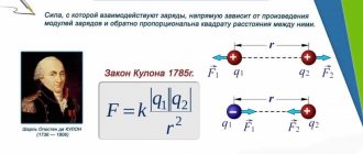
Ohm's law
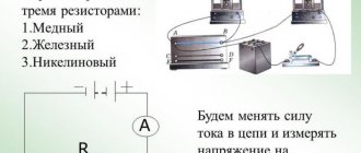
After Faraday's discovery of electromagnetic induction in 1831, the first direct and then alternating current generators appeared. The advantage of the latter is that alternating current is transmitted to the consumer with less losses. The value of current in an AC circuit is directly proportional to the voltage in the circuit and inversely proportional to the impedance of the circuit.
Ohm's law for a complete circuit - definition and formula
Ohm's Law shows the relationship between voltage (V), current (I) and resistance (R). This can be written in three different ways:
V = I × R
or
I = V/R
or
R = V/I
Where:
- V – voltage in volts (V);
- I – current strength in amperes (A);
- R – resistance in ohms (Ohm);
For most circuits, amps are too large and ohms too small. Therefore, milliamps and kilo-ohms can be substituted into the formula. If the current is set in milliamps (mA), then the resistance must be in kilo-ohms (kOhm) and vice versa. Voltage is always in volts.
Modifications of Ohm's law.
To make it easier to remember the three different versions of the definition of Ohm’s Law, you can use the “VIR triangle”.
- Georg Simon OhmIf we need to calculate the voltage, we close V with our finger. We are left with I and R. They are at the same level, which means we put a multiplication sign between them. It turns out: V = I × R.
- If we calculate the current, we close I with our finger. We are left with V above R. This means the voltage is divided by the resistance: I = V/R.
- We proceed in a similar way when calculating resistance. We close R. What remains is V over I. This means: R = V/I.
Ohm's law definition: Current is directly proportional to voltage and inversely proportional to resistance. There is also a special case - Ohm's Law for a section of a circuit - the current strength in a section of a circuit is directly proportional to the voltage at the ends of the section and inversely proportional to the resistance of this section.
Ohm's law - the basis of electrical engineering
This basic equation, used to study electrical circuits, was obtained experimentally by Georg Simon Ohm. He was born in Erlangen Germany in 1787 and entered the university of that city in 1805, where he received his doctorate. Georg taught mathematics in schools and conducted physics experiments in the school physics laboratory, trying to understand the principles of electromagnetism.
In 1827, he published papers describing a mathematical model of how circuits conduct heat in the works of Fourier. Ohm obtained experimental data on the basis of which he was able to formulate his law for the first time on January 8, 1826. He established that the potential difference between two points in a circuit is equal to the product of the current between them and the total resistance of all electrical devices. The greater the battery's voltage, or its total electrical potential difference, the greater its current will be. Likewise, with more resistance it will be less.
But his research did not find proper understanding and Georg left his work in Cologne. Only in 1833 did he receive a professorship in Nuremberg. Ohm's findings served as a catalyst for the latest research in electricity. In 1841, the scientist was awarded the Copley Medal, and in 1872, the "Ohm" was adopted as a unit of resistance in electrical circuits.
Ohm's Law for a complete electrical circuit describes the flow of current through conductive metals when different voltage levels are applied. Some materials, such as electrical wires, have little resistance to current flow—this type of material is called a conductor.
Important! In other cases, the material may prevent current flow but still allow it to be used. In electrical circuits, these components are often called resistors. There are materials that practically do not allow current to pass through, they are called insulators.
What can be understood by “Ohm’s Law”?
Ohm's law in differential and integral form is an empirical relationship that accurately describes the conductivity of the vast majority of conductive materials. However, some materials do not obey Ohm's law; they are called “non-ohmic”. The law was named after the scientist Georg Ohm, who published it in 1827. It describes voltage and current measurements using simple electrical circuits containing various lengths of wire. Ohm explained his experimental results with a slightly more complex equation than the modern form above.
The concept of Ohm's law in differential. form is also used to denote various generalizations, for example, its vector form is used in electromagnetism and materials science:
J=σE,
where J is the number of electrical particles in a specific location of the resistive material, e is the electric field at this location and σ (sigma) is the material, depending on the conductivity parameter. Gustav Kirchhoff formulated the law exactly this way.
Ohm's law formula
Ohm's First Law states that the potential difference between two points of a resistor is proportional to the current. Moreover, according to this law, the relationship between potential and current is always constant for ohmic resistors.
V = RI, where:
V—voltage/electric potential (V);
R—electrical resistance (ohm);
I - electric current.
Formula
In it, U is a scalar quantity and is measured in (B). The difference in electrical potential between two points in a circuit indicates the presence of electrical resistance. When I passes through a resistive element R, a drop in electrical potential occurs. This difference occurs due to energy dissipation called the Joule effect. I measures the flow of charges through the body in (A) and is directly proportional to the resistance of the wire.
Ohm's second law states that electrical resistance R is a property of a body that regulates the permeability of I. This property depends on the geometric factors of the body, such as the length or cross-sectional area of the section and on the value R caused. Its amount depends solely on the material of the section.
R= ρ*L/S, where:
R—electrical resistance (Ohm);
ρ—electrical resistivity of the wire (Ohm.m);
L is the length of the conductor (m);
S is the cross-sectional area of the wire (m²).
An ohmic resistor is any body capable of presenting a constant resistance for a given voltage range. The voltage versus current plot for ohmic resistors is linear. A resistor can be considered ohmic in the range in which its potential increases linearly with increasing I.
Resistance can be understood as the slope of the line given by the tangent of the angle. As is known, tangent is defined as the ratio between the opposite and adjacent sides, and, in the case where the resistance is ohmic, can be calculated by the formula: R = U / I.
Triangle
To help remember the formula, you can use a triangle with one side horizontal and the apex at the top, like a pyramid. This is sometimes called Ohm's triangle law. In its upper corner is the letter V, in the left corner is the letter I, and in the lower right corner is R.
Note! To use a triangle, cover the unknown parameter and then calculate it from the other two. If they are on the same line they are multiplied, but if one is above the other they should be separated. In other words, if I needs to be calculated, the voltage is divided by the resistance, that is, V/R.
Where and when can Ohm's law be applied?
Ohm's law in the form mentioned is valid within fairly wide limits for metals. It is carried out until the metal begins to melt. A less wide range of applications is in solutions (melts) of electrolytes and in highly ionized gases (plasma).
When working with electrical circuits, sometimes you need to determine the voltage drop across a certain element. If it is a resistor with a known resistance value (it is marked on the case), and the current passing through it is also known, you can find out the voltage using Ohm’s formula without connecting a voltmeter.
Importance of Ohm's Law
Ohm's law, in differential and integral form, was probably the most important early description of the physics of electricity. Today we consider this almost obvious, but when Ohm first published his work, this was not the case. Critics reacted with hostility to his interpretation. They called his works “mere fantasies,” and the German Minister of Education declared that “a professor who preaches such heresy is not worthy of teaching science.”
The prevailing scientific philosophy in Germany at the time argued that it was not necessary to conduct experiments to develop an understanding of nature. In addition, Geogr's brother Martin, a mathematician by profession, fought against the German educational system. These factors hindered the acceptance of Ohm's work, and his work did not become widely accepted until the 1840s. However, Ohm was recognized for his contributions to science long before his death.
Ohm's law in differential and integral form is an empirical law, a summary of the results of many experiments that have shown that current is approximately proportional to the electric field voltage for most materials. It is less fundamental than Maxwell's equations and is not suitable in all situations. Any material will be destroyed by a sufficient electric field.
Ohm's law was observed across a wide range of scales. At the beginning of the 20th century, Ohm's law was not considered at the atomic scale, but experiments confirm the opposite.
Electrical resistance
Electrical resistance is a physical quantity that characterizes the resistance of a conductor or electrical circuit to electric current.
Electrical resistance is defined as the proportionality coefficient $R$ between voltage $U$ and direct current $I$ in Ohm's law for a section of a circuit.
The unit of resistance is called ohm (Ohm) in honor of the German scientist G. Ohm, who introduced this concept into physics. One ohm ($1$ Ohm) is the resistance of a conductor in which, at a voltage of $1$ V, the current strength is equal to $1$ A.
Resistivity
The resistance of a homogeneous conductor of constant cross-section depends on the material of the conductor, its length $l$ and cross-section $S$ and can be determined by the formula:
Capacitance
Let us assume that a capacitor of capacitance $C$ is included in a section of the circuit, and $R=0$ and $L=0$. We will consider the current strength ($I$) to be positive if it has the direction indicated in Fig. 2. Let the charge on the capacitor be equal to $q$.
Figure 2.
We can use the following relationships:
If $I(t)$ is defined by equation (1), then the charge is expressed as:
where $q_0$ is an arbitrary constant charge of the capacitor, which is not associated with current fluctuations, so we can assume that $q_0=0.$ We obtain the voltage equal to:
Formula (6) shows that voltage fluctuations on a capacitor lag behind current fluctuations in phase by $frac{pi }{2}.$ The voltage amplitude across the capacitor is equal to:
The quantity $X_C=frac{1}{omega C}$ is called reactive capacitance (capacitance, apparent resistance of a capacitance). If the current is constant, then $X_C=infty $. This means that no direct current flows through the capacitor. From the definition of capacitance it is clear that at high oscillation frequencies, small capacitances are small resistances to alternating current.
Do you need advice on your academic work? Ask your teacher a question and get an answer in 15 minutes! Ask a Question
Transition from the integral form of Ohm's law to the differential one
Let's find the connection between the current density vector ($\overrightarrow{j}$) and the electric field strength vector ($\overrightarrow{E}$) at the same point of the conducting medium. If the substance is isotropic, then $\overrightarrow{j}\uparrow \uparrow \overrightarrow{E}$. Let us select a hypothetical cylinder in the vicinity of the point under consideration, the generators of which are parallel to the vectors of field strength and current density (Fig. 1).
Help with student work on the topic Differential form of Ohm's law
Coursework 450 ₽ Essay 280 ₽ Test paper 210 ₽
Receive completed work or advice from a specialist on your educational project Find out the cost
Rice. 1
A current flows through the cross section of the cylinder (dS) (Fig. 1), the strength of which will be written as:
The voltage applied to the cylinder can be expressed as:
where $E$ is the field strength at the point under consideration. The resistance of the cylinder will be expressed as:
Substituting formulas (3), (4), (5) into expression (1), we obtain:
Let's make some reductions and get:
Let's replace resistivity ($\rho $) with conductivity ($\sigma $). We take advantage of the fact that the voltage and current density vectors have the same directions and finally write:
Equation (8) is called Ohm's law in differential form. Unlike Ohm's law in integral form (1), equation (8) contains quantities that characterize the electrical state of the medium at a point.
Do you need proofreading or review of academic work? Ask a question to the teacher and get an answer in 15 minutes! Ask a Question
The field strength that is included in equation (8) is the field inside a conducting medium in the presence of current. However, if the medium is homogeneous, then in most cases this field coincides with the electrostatic field, that is, the field that would exist between the electrodes with the same voltage on them as in the presence of current. Consequently, in a homogeneous conductor, the electrostatic field strength lines coincide with the current lines.
Inductive reactance
Let a section of the circuit have only inductance (Fig. 3). We will assume $I>0$ if the current is directed from $a$ to $b$.
Figure 3.
If a current flows in the coil, then a self-inductive emf appears in the inductance, therefore, Ohm’s law will take the form:
By condition $R=0. The mathcal E$ of self-induction can be expressed as:
From expressions (8), (9) it follows that:
The voltage amplitude in this case is equal to:
where $X_L is $inductive reactance (apparent inductive resistance).
Ohm's law for a circuit
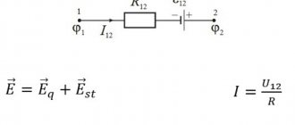
Ohm’s law for a section of a circuit can, of course, be described by the formula known from a school physics course: I=U/R, but I think it’s worth making some changes and clarifications. Let's take a closed electrical circuit and consider its section between points 1-2. For simplicity, I took a section of the electrical circuit that did not contain sources of emf (E).
So, Ohm's law for the section of the circuit under consideration has the form:
φ1-φ2=I*R, where
- I – current flowing through a section of the circuit.
- R is the resistance of this section.
- φ1-φ2 – potential difference between points 1-2.
If we take into account that the potential difference is voltage, then we come to the derivative formula of Ohm's law, which is given at the beginning of the page: U=I*R. This is the formula of Ohm's law for the passive section of the circuit (containing no sources of electricity).
In an unbranched electrical circuit (Fig. 2), the current strength in all sections is the same, and the voltage in any section is determined by its resistance:
- U1=I*R1
- U2=I*R2
- Un=I*Rn
- U=I*(R1+R2+…+Rn
From here you can obtain formulas that are useful in practical calculations. For example:
U=U1+U2+…+Un or U1/U2/…/Un=R1/R2/…/Rn
The calculation of complex (branched) circuits is carried out using Kirchhoff's laws.
Ohm's law for a section of a circuit.
For EMF
Before considering Ohm's law for a complete (closed) circuit, I will give a sign rule for EMF, which states: If inside the EMF source the current flows from the cathode (-) to the anode (+) (the direction of the field strength of external forces coincides with the direction of the current in the circuit, then the EMF of such a source is considered positive, otherwise the EMF is considered negative.
A practical application of this rule is the possibility of bringing several sources of EMF in a circuit to one with the value E=E1+E2+…+En, naturally, taking into account the signs determined by the above rule. For example (Fig. 3.3) E=E1+E2-E3. In the absence of a back-to-back source E3 (in practice this almost never happens), we have a widespread serial connection of batteries, in which their voltages are summed.
For a complete chain
Ohm's law for a complete circuit - it can also be called Ohm's law for a closed circuit, has the form I=E/(R+r). The above formula for Ohm's law contains the notation r, which has not yet been mentioned. This is the internal resistance of the EMF source. It is quite small, in most cases it can be neglected in practical calculations (provided that R>>r - the circuit resistance is much greater than the internal resistance of the source). However, when they are comparable, the value of r cannot be neglected.
As an option, we can consider the case in which R=0 (short circuit). Then the given formula of Ohm's law for the complete circuit will take the form: I=E/r, that is, the value of the internal resistance will determine the short-circuit current. This situation may well be real. Ohm's law is discussed here quite briefly, but the formulas given are sufficient to carry out most calculations, examples of which, as other materials are posted, I will give.
A complete circuit is made up of a section (sections), as well as a source of EMF. That is, in fact, the internal resistance of the EMF source is added to the existing resistive component of the circuit section. Therefore, it is logical to slightly change the above formula:
I = U / (R + r)
Of course, the value of the internal resistance of the EMF in Ohm’s law for a complete electrical circuit can be considered negligible, although this resistance value largely depends on the structure of the EMF source. However, when calculating complex electronic circuits, electrical circuits with many conductors, the presence of additional resistance is an important factor.
Both for a section of a circuit and for a complete circuit, the natural moment should be taken into account - the use of constant or variable current. If the points noted above, characteristic of Ohm’s law, were considered from the point of view of using direct current, accordingly with alternating current everything looks somewhat different.
Generalized Ohm's law. Ohm's law for a circuit section
Ohm's law for a section of a circuit.
more. Then Ohm's law for this section of the circuit will look like:
Generalized Ohm's law.
more .
1) (EMF source – generator)
2) (EMF source – motor)
Ohm's law for a circuit containing an EMF source (generalized Ohm's law):
I=
Kirchhoff's first and second laws. Calculation of an electrical circuit according to Kirchhoff's laws (using the example of an electrical circuit).
Kirchhoff's first law - the algebraic sum of all currents converging at a node is equal to zero.
(Currents directed towards the node are conventionally assumed to be negative, and those directed away from it are assumed to be positive). On
-I1-I2-I3+I4+I5=0
I1+I2+I3=I4+I5
Kirchhoff's second law - Along a closed circuit, the algebraic sum of the voltage drops in the individual elements of the circuit is equal to the algebraic sum of the EMF included in this circuit (or 0, if the circuit does not contain an EMF)
An example of a circuit calculation based on Kirchhoff's laws:
· The number of equations according to Kirchhoff’s first law is equal to the number of nodes minus 1
1) I1-I2=0
2) -I1+I2=0
3) -I1+ I3+I4=0
· The number of equations according to Kirchhoff’s second law is equal to the number of independent circuits:
Serial, parallel and mixed connection of elements.
A) A series connection is a connection in which the same current flows through all elements I=I1=I2=I3, while U=U1+U2+U3= I1R1+I2R2+I3R3=I*(R1+R2 +R3). Where Req= R1+R2+R3
I*Req=U
With a series connection, all resistances can be replaced by one equivalent one.
B) Parallel connection - with it, all elements are connected to one pair of nodes, i.e. are under the same voltage. I1=U1/R1; I2=U2/R2; I3=U3/R , then I=I1+I2+I3 . Then U/Req=U1/R1+U2/R2+U3/R3 and therefore 1/Req=1/ R1+1/R2+1/ R3
, and
I=U/Req
B) A mixed connection is a connection of elements that contains elements connected in series and in parallel. Req=R1+R2+R6+R1R2R3/(R1R2+R2R3+R1R3)
Method of equivalent transformations with one source.
Given: R1, R2, R3, R4, R5,R6, E
Find:
I.
R456=R4+R5+R6; R12=R1+R2; then we transform this circuit (Fig. 1) into an equivalent one (Fig. 2) taking into account these transformations.
R3456=(R3*R456)/(R3+R456). Based on this transformation, we transform the circuit (Fig. 2) into an equivalent one (Fig. 3). I1=E/(R12+R3456)
Method I Uab=E-I1R12; I2=Uab/R3; I3=Uab/R456.
II method. It uses a "scatter" formula. I2=I1*R456/(R3+R456); I3=I1*R3/(R3+R456)
In the case when there is a current source in an electrical circuit, only the “scatter” formula can be used to determine the current, or to determine the current in the branches.
| Fig.1 |
| Fig.2 |
Loop current method
the equations of the loop current method are compiled only according to Kirchhoff’s second law, but not for real, but for imaginary currents circulating in closed loops, i.e. in the case of choosing the main circuits equal to the currents of the communication branches. The number of equations is equal to the number of independent contours, i.e. number of connection branches of the graph. Kirchhoff's first law is satisfied automatically. The contours can be chosen arbitrarily, as long as their number is equal and each new contour contains at least one branch that is not included in the previous ones. Such contours are called independent.
The directions of true and loop currents are chosen arbitrarily. Choosing positive directions before starting the calculation may not determine the actual directions of currents in the circuit. If, as a result of the calculation, any of the currents, as when using equations according to Kirchhoff’s laws, turns out with a “-” sign, this means that its true direction is opposite.
When writing equations, keep the following in mind:
· - the sum of the resistances included in i-
th contour;
· - sum of resistances common to i-
th and
k-th
contours, and ;
· terms on the main diagonal are always written with a “+” sign;
· the “+” sign is placed in front of the remaining terms if, through the total resistance i-
the th and
kth
loop currents pass in the same direction, otherwise the sign “-” is indicated;
· if i-
the th and
kth
circuits do not have common resistances, then;
· on the right side of the equations the algebraic sum of the EMF entering the circuit is written: with a “+” sign if the direction of the EMF coincides with the selected direction of the loop current, and “-” if it does not coincide.
Example of circuit calculation using the loop current method
Let us have a diagram according to Fig. 3.
Let us express the branch currents in terms of loop currents:
;
;;
; .
Bypassing the contour of the aeda,
according to Kirchhoff's second law we have:
.Because the:
That:
Thus, we obtained an equation for the first circuit regarding the loop currents. Similarly, you can create equations for the second, third and fourth circuits
Together with the first, solve them with respect to the loop currents and then, using the equations connecting the loop currents and branch currents, find the latter.
Ohm's law for alternating current
If there is inductance or capacitance in an AC circuit, its reactance must be taken into account. In this case, the entry for Ohm's Law will look like:
I = U/Z
Here Z is the total (complex) resistance of the circuit - impedance. It includes active R and reactive X components. Reactance depends on the ratings of the reactive elements, on the frequency and shape of the current in the circuit. You can learn more about complex resistance on the impedance page.
Quantum beginning
The dependence of the current density on the applied electric field is fundamentally quantum-mechanical in nature (classical quantum permeability). A qualitative description of Ohm's law can be based on classical mechanics using the Drude model, developed by the German physicist Paul Drude in 1900. Because of this, Ohm's law has many forms, such as the so-called Ohm's law in differential form.
Ohm's law for a closed circuit
If an external circuit with resistance R is connected to the power source, current will flow in the circuit taking into account the internal resistance of the source:
I – Current strength in the circuit.
– Electromotive force (EMF) – the magnitude of the power source voltage independent of the external circuit (without load). Characterized by the potential energy of the source. r – Internal resistance of the power supply.
For electromotive force, the external resistance R and internal r are connected in series, which means the magnitude of the current in the circuit is determined by the value of the emf and the sum of the resistances: I = /(R+r) .
The voltage at the terminals of the external circuit will be determined based on the current and resistance R by the relationship that has already been discussed above: U = IR.
Voltage U, when connecting a load R, will always be less than the EMF by the value of the product I*r, which is called the voltage drop across the internal resistance of the power source. We encounter this phenomenon quite often when we see partially discharged batteries or accumulators in operation.
As the discharge progresses, their internal resistance increases, therefore, the voltage drop inside the source increases, which means the external voltage U = – I*r decreases.
The lower the current and internal resistance of the source, the closer in value its EMF and the voltage at its terminals U. If the current in the circuit is zero, therefore = U. The circuit is open, the EMF of the source is equal to the voltage at its terminals.
In cases where the internal resistance of the source can be neglected (r ≈ 0), the voltage at the source terminals will be equal to the EMF (≈ U) regardless of the external circuit resistance R. Such a power source is called a voltage source.
Ohm's law formula for a closed circuit
Let us derive the formula for Ohm's law for a closed circuit.
External forces, moving the charge $Δq$ in time $Δt$, do work:
$$A_{st}=\mathscr{E}q$$
Current, by definition, is equal to the ratio of the charge passing through the conductor to the time of passage, that is:
$$I={Δq\over Δt}$$
Substituting the charge value from this formula into the previous one, we get:
$$A_{st}=\mathscr{E}IΔt$$
All this work will be released as heat across the circuit resistance. The circuit resistance consists of two components: the resistance of the circuit itself $R$ and the resistance of the EMF source $r$. Taking into account the Joule-Lenz law:
$$ A_{st}=I^2RΔt+I^2rΔt$$
Equating the left sides of the formulas, we get:
$$\mathscr{E}IΔt=I^2RΔt+I^2rΔt$$
After reductions and transformations we have:
$$I={\mathscr{E}\over R+r}$$
The current strength in a closed circuit is equal to the ratio of the EMF in the closed circuit to the sum of the circuit resistance and the internal resistance of the EMF source.
Nonlinear elements and circuits
Ohm's law is not a fundamental law of nature and can be applied in limited cases, for example, for most conductors. It cannot be used to calculate voltage and current in semiconductor or vacuum devices, where this dependence is not proportional and can only be determined using the current-voltage characteristic (volt-ampere characteristic). This category of elements includes all semiconductor devices (diodes, transistors, zener diodes, thyristors, varicaps, etc.) and vacuum tubes. Such elements and the circuits in which they are used are called nonlinear.
Ohm's Law for AC Power
The well-known Ohm's law triangle, used for constant electron flow circuits, can only be used for alternating discharge if the load is purely resistive. However, most systems contain series or parallel combinations of resistance, capacitance and inductance. This results in voltage and discharge mismatch and the load becomes challenging. In purely capacitive systems, the discharge waveform leads the voltage waveform, whereas in inductive circuits the intensity leads the discharge. In circuits containing both inductors and capacitors, the waveform will not be in phase except at resonance. The general term for resistance is impedance and is represented by the symbol Z. The impedance triangle is shown below:
You might be interested in this: Features of SMD capacitors
Triangle
The triangle is used in exactly the same way, with some exceptions.
Note : When measuring voltage or discharge, the meter will only show correct values over a limited frequency range . This is usually true for DC up to 400 Hz, but this can be determined by checking the instrument specifications.
For circuits in which voltage and current are only in phase, the following pie chart can be used.
Diagram
Ohm's law for a circuit section
From the school physics course, everyone is well aware of the classic interpretation of Ohm's Law: The current strength in a conductor is directly proportional to the voltage at the ends of the conductor and inversely proportional to its resistance.
I = U/R
This means that if a voltage U = 1 Volt is applied to the ends of a conductor with a resistance of R = 1 Ohm, then the magnitude of the current I in the conductor will be equal to 1/1 = 1 Ampere.
From here two more useful relationships follow: If a current of 1 Ampere flows in a conductor with a resistance of 1 Ohm, then at the ends of the conductor there is a voltage of 1 Volt (voltage drop).
U = IR
If there is a voltage of 1 Volt at the ends of the conductor and a current of 1 Ampere flows through it, then the resistance of the conductor is 1 Ohm.
R = U/I
The above formulas in this form can be applied to alternating current only if the circuit consists only of active resistance R. In addition, it should be remembered that Ohm’s Law is valid only for linear elements of the circuit.
A simple online calculator is provided for practical calculations. Ohm's law. Calculation of voltage, resistance, current, power.
Examples of problems using Ohm's law for a closed circuit
A rheostat with a resistance of 4 Ohms is connected to an EMF source of 10 V and an internal resistance of 1 Ohm. Find the current in the circuit and the voltage at the source terminals.
| Given: | Solution: |
|
|
When a resistor with a resistance of 20 Ohms was connected to a battery of galvanic cells, the current in the circuit was 1 A, and when a resistor with a resistance of 10 Ohms was connected, the current became 1.5 A. Find the emf and internal resistance of the battery.
| Given: | Solution: |
|
|
Scope of application
Ohm's law is not a basic law in physics, it is just a convenient dependence of some values on others, which is suitable in almost any practical situation. Therefore, it will be easier to list situations when the law may not work:
- If there is inertia of charge carriers, for example in some high-frequency electric fields;
- In superconductors;
- If the wire heats up to such an extent that the current-voltage characteristic ceases to be linear. For example, in incandescent lamps;
- In vacuum and gas radio tubes;
- In diodes and transistors.
Interesting read: instructions on how to ring a transistor.
Serial and parallel connection of elements
For elements of an electrical circuit (section of a circuit), a characteristic point is a serial or parallel connection. Accordingly, each type of connection is accompanied by a different pattern of current flow and voltage supply. In this regard, Ohm's law is also applied differently, depending on the option of including elements.
Circuit of series-connected resistive elements
In relation to a series connection (a section of a circuit with two components), the following formulation is used:
- I = I1= I2 ;
- U = U1+ U2 ;
- R = R1+ R2
This formulation clearly demonstrates that, regardless of the number of resistive components connected in series, the current flowing through a section of the circuit does not change in value. The magnitude of the voltage applied to the effective resistive components of the circuit is the sum and totals the value of the emf source.
In this case, the voltage on each individual component is equal to: Ux = I * Rx. The total resistance should be considered the sum of the values of all resistive components in the circuit.
Circuit of parallel connected resistive elements
In the case when there is a parallel connection of resistive components, the following formulation is considered fair in relation to the law of the German physicist Ohm:
- I = I1+ I2 … ;
- U = U1= U2 … ;
- 1 / R = 1 / R1+ 1 / R2 + …
Options for creating circuit sections of a “mixed” type, when parallel and serial connections are used, are not excluded. For such options, the calculation is usually carried out by initially calculating the resistive rating of the parallel connection. Then the value of the resistor connected in series is added to the result obtained.
Integral and differential forms of the law
All of the above points with calculations are applicable to conditions when conductors of, so to speak, “homogeneous” structure are used in electrical circuits. Meanwhile, in practice, one often has to deal with the construction of schematics, where the structure of the conductors changes in different sections. For example, wires of a larger cross-section or, conversely, a smaller one, made from different materials, are used.
To take into account such differences, there is a variation of the so-called “differential-integral Ohm’s law.” For an infinitesimal conductor, the current density level is calculated depending on the voltage and conductivity value.
For the differential calculation, the formula is taken: J = ό * E. For the integral calculation, accordingly, the formulation is: I * R = φ1 – φ2 + έ However, these examples are rather closer to the school of higher mathematics and are not actually used in the real practice of a simple electrician.
Current strength
Electric current is the ordered (directed) movement of charged particles. Electric current strength is a quantity ($I$) that characterizes the ordered movement of electric charges and is numerically equal to the amount of charge $∆q$ flowing through a certain surface $S$ (cross section of the conductor) per unit time:
$I={∆q}/{∆t}$
So, to find the current strength $I$, it is necessary to divide the electric charge $∆q$ that passed through the cross section of the conductor during the time $∆t$ by this time. The strength of the current depends on the charge carried by each particle, the speed of their directional movement and the cross-sectional area of the conductor.
Consider a conductor with cross-sectional area $S$. The charge of each particle is $q_0$. The volume of the conductor, limited by sections $1$ and $2$, contains $nS∆l$ particles, where $n$ is the concentration of particles. Their total charge is $q=q_{0}nS∆l$. If the particles move with an average speed $υ$, then during the time $∆t={∆l}/{υ}$ all particles contained in the volume under consideration will pass through the cross section $2$. The current strength is therefore equal to:
$I={∆q}/{∆t}={q_{0}nS∆l·υ}/{∆l}=q_{0}nυS$
In the SI, the unit of current is the basic one and is called the ampere (A) in honor of the French scientist A. M. Ampere (1755-1836). The current strength is measured with an ammeter. The principle of the ammeter is based on the magnetic action of current. An estimate of the speed of ordered movement of electrons in a conductor, carried out using the formula for a copper conductor with a cross-sectional area of $1mm^2$, gives a very insignificant value - $∼0.1$ mm/s.
Joule-Lenz law
The Joule-Lenz law states: the amount of heat released in a conductor in a section of an electrical circuit with resistance $R$ when a direct current $I$ flows through it for a time $t$ is equal to the product of the square of the current and the resistance and time:
$Q=I^2Rt$
The law was established in 1841 by the English physicist J. P. Joule, and in 1842 it was confirmed by the precise experiments of the Russian scientist E. H. Lenz. The very phenomenon of heating a conductor when current passes through it was discovered back in 1800 by the French scientist A. Fourcroy, who managed to heat an iron spiral by passing an electric current through it.
From the Joule-Lenz law it follows that when conductors are connected in series, since the current in the circuit is the same everywhere, the maximum amount of heat will be released on the conductor with the greatest resistance. This is used in technology, for example, for spraying metals.
In a parallel connection, all conductors are under the same voltage, but the currents in them are different. From the formula ($Q=I^2Rt$) it follows that, since, according to Ohm’s law, $I={U}/{R}$, then
$Q={U^2t}/{R}$
Therefore, more heat will be generated on a conductor with less resistance.
If in the formula ($A=IUt$) we express $U$ in terms of $IR$, using Ohm's law, we obtain the Joule-Lenz law. This once again confirms the fact that the work of the current is spent on heat generation at the active resistance in the circuit.
Meaning of Ohm's Law
Ohm's law determines the current strength in an electrical circuit at a given voltage and known resistance. It allows you to calculate the thermal, chemical and magnetic effects of current, as they depend on the strength of the current.
Ohm's Law is extremely useful in engineering (electronic/electrical) because it deals with three basic electrical quantities: current, voltage and resistance. It shows how these three quantities are interdependent at the macroscopic level.
If it were possible to characterize Ohm's law in simple words, then it would clearly look like this:
It follows from Ohm's law that it is dangerous to close a conventional lighting network with a conductor of low resistance. The current will be so strong that it can have serious consequences.
Problem 1.1
Calculate the current passing through a copper wire 100 m long, with a cross-sectional area of 0.5 mm2, if a voltage of 12 V is applied to the ends of the wire.
The task is simple; it consists in finding the resistance of a copper wire and then calculating the current strength using the Ohm's law formula for a section of the circuit. Let's get started.
Other forms of Ohm's law
Ohm's Law in differential form is a very important concept in electrical/electronics engineering because it describes both voltage and resistance. All this is interconnected at the macroscopic level. When studying electrical properties at the macro or microscopic level, a more related equation is used, which can be called "Ohm's equation", having variables that are closely related to the scalar variables V, I and R of Ohm's law, but which are a constant function of position in the conductor.