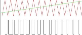
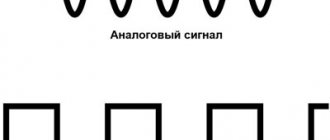
general information
The main parameters of the pulse sequence include:
- l pulse amplitude – Um,
- l pulse duration – tu,
- l pause duration – tn,
- l repetition period T or frequency f = 1/T repetition.
If the duration tu of all pulses included in the sequence and all pauses tn is constant over time, then it is called periodic.
An important parameter of the periodic pulse process is the duty cycle of the pulses S. The duty cycle of the pulses is the ratio of the repetition period to the pulse duration, calculated by the formula:
The efficiency of S in device control is achieved with a stable signal frequency. Sometimes the inverse value D is used - the fill factor, calculated by the formula:
If tu and tn are equal, the duty cycle is 2, and the signal is called a square wave. S and D are dimensionless quantities, since time is divided by time. Digital devices use pulses of various shapes. The pulse shape is a graphical representation of the law of change in pulse voltage over time. In Fig. The waveforms are shown below:
- a – rectangular,
- b – trapezoidal,
- c – exponential,
- g – bell,
- d – stepped,
- e – sawtooth.
Types of pulse signals
The technical characteristics of the pulse shape are associated with a quantitative assessment of the main parameters of the pulse, the properties of its individual sections, which play different roles when the pulse acts on the device. In Fig. Above are idealized pulse shapes. Due to transient processes in devices (pulse formation and amplification), there is a real shape, for example, of a rectangular pulse (Fig. below).
Real pulse shape
The main parameters of the pulse are:
- l Pulse swing – Um,
- l Pulse duration – ti,
- l Duration of the leading edge – tf,
- l Duration of the trailing edge – tsp,
- l Top decline – ΔU,
- l Swing of the trailing edge – Um arr.
- l Duration of the trailing edge release – t and arr.
The indicated values are read between levels 0.1 and 0.9 of the amplitude in microseconds, depending on the frequency of the signal. Amplitude - in volts.
You can determine the parameters of a pulse signal using an oscilloscope, frequency meter or multimeter.
Pulses and triggering signals (triggers)
General characteristics of the pulse signal
Types of pulse signals. Pulse technology refers to the field of radio electronics that studies the formation of pulse signals and their passage through electrical circuits. A pulse signal can consist of one or a series of pulses. An impulse is understood as the rapid appearance and disappearance of current or voltage, i.e., the short-term effect of current or voltage on an electrical circuit or device. In pulse technology, there are two types of pulse signals - video pulses
(Fig. 1, a), which are short-term one-sided (relative to the time axis) changes in voltage or current in a direct current circuit, and
radio pulses
(Fig. 1, b)—a signal consisting of high-frequency oscillations of voltage or current, the envelope of which follows the shape video pulse. In pulse technology, video pulses are mainly considered.
Pulse shape
Pulses can have rectangular, trapezoidal, bell, triangular and exponential
Rice. 1. Single pulses: a - video pulse, b - radio pulse
shape (Fig. 2). In a pulse of various shapes, a front, a peak, and a fall are distinguished. Pulses can be of positive or negative polarity. Pulses of positive polarity on the graphs are depicted above the horizontal time axis, and negative ones - below the axis.
Pulse parameters. Each pulse is characterized by amplitude A
(see Fig. 1, a), pulse duration
t
and, duration of the front
t
f, decay
t
c, decrease in the peak Δ
A,
as well as the power in the pulse
P
and.
Rice. 2. Pulse shapes: a - rectangular, b - trapezoidal, c - bell-shaped, e - triangular, d - exponential
Amplitude
A unipolar pulse is characterized by the magnitude (range) of voltage or current from zero to the maximum value of a pulse of a given shape.
In a two-way pulse, the value from the top of the positive to the top of the negative pulse is called the full swing of the pulse
(total amplitude
A
p).
Pulse duration
t
p is the time interval during which current or voltage acts on an electrical circuit.
In real circuits, the shape of the pulses is distorted, so the duration is determined at the level of 0.1 A
and less often at the base of the pulse.
The active pulse duration t
and.a is measured at 0.5
A.
Front duration t
f and decay
tc
is estimated by the time interval during which the pulse amplitude increases from 0.1 to 0.9 of its maximum value and falls from 0.9
A
to 0.1
A.
In most cases, it is desirable to have minimum
t
f and
to.
Reduction of peak Δ A
should practically not exceed (0.01-0.05)
A.
The power in a pulse is characterized by the ratio of the energy W released in the circuit during the passage of the pulse to its duration t
And:
For a periodic sequence of pulses (Fig. 3, a)
characterized by pulses occurring at regular intervals. It is characterized by the following parameters.
Follow-up period T
and is the time interval from the moment of appearance of one pulse to the moment of appearance of the next pulse of the same polarity.
The repetition frequency
F
and
,
which is the reciprocal of the repetition period, i.e.
Pause duration
T
and
is
the time between the end of one pulse and the beginning of another:
Pulse duty cycle Q,
defined as the ratio of the period
T
and to the duration
t
and
The average value of the pulse current (voltage) is obtained if the pulse current (voltage) is evenly distributed over the entire period so that the area of the rectangle I
cf
T
and (Fig. 3, b) was equal to the pulse area
S and
| The duty cycle is the reciprocal of the duty cycle, showing what part of the period the pulse occupies: |
| Rice. 3. Periodic sequence of pulses: a - rectangular, b - bell-shaped |
The average power PСр is determined by the energy ratio W,
allocated in the circuit during the pulse repetition period Ti, to the duration of this period:
Obviously R
cf
T
and =
P
and
t
and, whence
Electronic devices for pulse circuits are often selected based on average power.
Often in electronic circuits there is a need to generate different types of signals having different frequencies and shapes, such as square waves, square waves, triangular signals, sawtooth signals and various pulses.
These signals of various shapes can be used as synchronization signals, timing signals, or as trigger pulses. The first step is to understand the basic characteristics that describe electrical signals.
In technical terms, electrical signals are a visual representation of changes in voltage or current over time. That is, in fact, this is a graph of changes in voltage and current, where we plot time on the horizontal axis, and on the vertical axis we plot the voltage or current values at this point in time. There are many different types of electrical signals, but in general, they can all be divided into two main groups.
· Unipolar signals
are electrical signals that are always positive or always negative and do not cross the horizontal axis. Unidirectional signals include square waves, clock pulses, and trigger pulses.
· Bipolar signals
- These electrical signals are also called alternating signals because they alternate between positive and negative values, constantly crossing zero. Bipolar signals have a periodic change in the sign of their amplitude. The most common bidirectional signal is the sine wave.
Whether unidirectional, bidirectional, symmetrical, asymmetrical, simple or complex, all electrical signals have three common characteristics:
· Period
- this is the period of time after which the signal begins to repeat.
This time value is also called the period time
for sinusoids or
the pulse width
for square waves and is denoted by the
letter T.
· Frequency
is the number of times the signal repeats itself over a period of time equal to
1
second.
Frequency is the reciprocal of the time period, ( ). The unit of frequency is Hertz ( Hz
).
The frequency of 1Hz
is a signal that repeats
once
every
second
.
· Amplitude
is the amount of signal change.
It is measured in Volts ( V
) or Amperes (
A
), depending on which time dependence (voltage or current) we use.
Periodic signals
Periodic signals are the most common because they include sine waves. The alternating current in the outlet at home is a sinusoid, changing smoothly over time with a frequency of 50 Hz
.
The time that passes between individual repetitions of a sinusoid cycle is called its period
. In other words, this is the time it takes for the signal to start repeating.
The period can vary from fractions of a second to thousands of seconds, as it is related to its frequency. For example, a sinusoidal signal that requires 1
a second to complete a complete cycle has a period equal to one second.
Likewise, a sine wave that takes 5
seconds to complete a cycle has a period of
5
seconds, and so on.
So, the length of time it takes for a signal to complete a full cycle of its change before it repeats again is called the period of the signal
and is measured in seconds.
We can express the signal as the number of cycles T
per second as shown in the figure below.
Sine wave
Period time is often measured in seconds (s), milliseconds (ms), and microseconds (µs).
For a sinusoidal waveform, the time of the signal period can also be expressed in degrees, or in radians, given that one complete cycle is equal to 360°
(
T = 360°
), or, if in radians, then (
T =
).
Period and frequency are mathematically the reciprocals of each other. As the signal period time decreases, its frequency increases and vice versa.
The relationship between the signal period and its frequency:
Hz
c
One hertz is exactly equal to one cycle per second, but one hertz is a very small value, so you often see prefixes indicating the order of magnitude of the signal, such as kHz
,
MHz, GHz
and even
THz
| Prefix | Definition | Record | Period |
| Kilo | thousand | kHz | 1 ms |
| Mega | million | MHz | 1 µs |
| Giga | billion | GHz | 1 ns |
| Tera | trillion | THz | 1 ps |
Meander
Square waves are widely used in electronic circuits for timing and synchronization signals because they have a symmetrical square wave shape with equal half-cycle lengths. Almost all digital logic circuits use square wave signals at their inputs and outputs.
Since the shape of the meander is symmetrical, and each half of the cycle is the same, the duration of the positive part of the pulse is equal to the period of time when the pulse is negative (zero). For square waves used as timing signals in digital circuits, the duration of the positive pulse is called the fill time
period.
For a square wave, the fill time is equal to half the signal period. Since the frequency is equal to the reciprocal of the period, ( 1/T
), then the meander frequency:
For example, for a signal with a fill time of 10 ms, its frequency is:
Hz
Square waves are used in digital systems to represent the logic level1
" with large values of its amplitude and the logical level "
0
" with small values of amplitude.
If the filling time is not equal to 50% of the duration of its period, then such a signal already represents a more general case and is called rectangular
signal.
If or if the time of the positive part of the signal period is short, then such a signal is an impulse
.
Square wave
Rectangular signals differ from meanders in that the durations of the positive and negative parts of the period are not equal. Square wave signals are therefore classified as single-ended
signals.
In this case, I have depicted a signal that takes only positive values, although, in general, negative signal values can be significantly below the zero mark.
In the example shown, the duration of the positive pulse is longer than the duration of the negative one, although this is not necessary. The main thing is that the signal shape is rectangular.
The ratio of the signal repetition period to the duration of the positive pulse is called duty cycle:
The reverse duty cycle value is called the duty cycle
):
Calculation example
Let there be a rectangular signal with a pulse duration of 10 ms and a duty cycle of 25%. It is necessary to find the frequency of this signal.
The duty cycle is 25% or ¼, and coincides with the pulse width, which is 10ms. Thus, the signal period should be equal to: 10ms (25%) + 30ms (75%) = 40ms (100%).
Hz
Square wave signals can be used to control the amount of power delivered to a load, such as a lamp or motor, by varying the duty cycle of the signal. The higher the duty cycle, the greater the average amount of energy must be supplied to the load, and, accordingly, a lower duty cycle means a lower average amount of energy supplied to the load. A great example of this is the use of pulse width modulation
in speed controllers.
The term pulse width modulation (PWM)
literally means “change in pulse width.”
Triangle signals
Triangle signals are generally bidirectional, non-sinusoidal signals that oscillate between positive and negative peak values. A triangle waveform is a relatively slowly rising and falling voltage at a constant frequency. The rate at which the voltage changes direction is equal for both halves of the period, as shown below.
Typically, for triangular signals, the duration of the signal's rise is equal to the duration of its fall, thereby giving a 50% duty cycle. By setting the amplitude and frequency of the signal, we can determine the average value of its amplitude.
In the case of an asymmetrical triangular waveform, which we can obtain by varying the rate of rise and fall by different amounts, we have another type of signal known as a sawtooth waveform.
.
Ramp signal
A ramp wave is another type of periodic waveform. As the name suggests, the shape of this signal resembles the teeth of a saw. A sawtooth signal can be a mirror image of itself, having either a slow rise but a very steep fall, or an extremely steep, nearly vertical rise and a slow fall.
The slow-rising ramp wave is the more common of the two waveform types, being almost perfectly linear. The sawtooth signal is generated by most function generators and consists of the fundamental frequency ( f
) and even harmonics. This means, from a practical point of view, that it is rich in harmonics, and in the case of, for example, music synthesizers, produces high-quality sound without distortion for musicians.
Pulses and triggering signals (triggers)
Although, technically, trigger signals and pulses are two separate types of signals, the differences between them are minor. The trigger signal is just a very narrow pulse. The difference is that a trigger can be of either positive or negative polarity, while a pulse can only be positive.
A pulse waveform, or pulse train as it is more commonly called, is a type of non-sinusoidal waveform similar to a square wave. The difference is that the pulse signal is often determined only by the duty cycle. For a triggering signal, the positive part of the signal is very short with sharp rises and falls, and its duration, compared to the period, can be neglected.
Very short pulses and triggering signals are designed to control moments in time at which, for example, the start of a timer, counter, switching of logical triggers occurs, as well as for controlling thyristors, triacs and other power semiconductor devices.
Other types of signals are usually obtained by combining or modulating (changing parameters using another signal), for example:
Amplitude modulated signal
Frequency modulated signal
Phase modulated signal
· Phase-frequency modulated signal
· Phase-code-keyed signal
Duty ratio control
Blocking generator: operating principle
Digital signals are used to control a variety of devices. The first application of such control was when transmitting information using Morse code. The signal is transmitted in short and long pulses. Each letter corresponds to a specific set of dots and dashes. Today this control method is used for PWM control.
By changing D (fill factor) from 0 to 1, the desired voltage is achieved at the output of the electronic device. In this way, you can control engine speed, lighting, display brightness, etc. When forming rectangular pulses, specially designed microcircuits are used, for example, NE555, NL494, KR1006VI1, IR2153, and microcontrollers: Arduino, AVR, SG2525A.
To ensure reliable operation of controlled devices, stringent requirements for their stability are imposed on the parameters of the pulse signal. This is achieved by using a quartz oscillator and a good transient response of the control pulse generation circuit.
ELECTRICAL IMPULSE
Rice. 1. Electrical pulses of different shapes: a – rectangular; b – trapezoidal; c – exponential; g – bell-shaped; d – radio pulse; A – amplitude; τti – pulse duration; tia - lasts...
ELECTRICAL PULSE, short-term abrupt change in electrical power. voltage or current. I. e. current or voltage (preferably of the same polarity), having a constant component and not containing HF oscillations, are called video pulses. Based on the nature of the change over time, video pulses are distinguished into rectangular, sawtooth, trapezoidal, bell-shaped, exponential and other shapes (Fig. 1, a–d). A real video pulse can have a rather complex shape (Fig. 2), which is characterized by amplitude $A$, duration τu (measured at a predetermined level, for example $0.1\, A$ or $0.5\, A$), front duration τf and decline τс (measured between the levels $0.1\, A$ and $0.9\, A$), the slope of the top $ΔA$ (expressed as a percentage of $A$). The most widely used are rectangular video pulses, on the basis of which synchronizing, control and information signals are formed in computing. technology, radar, television, digital systems for transmitting and processing information, etc. Sawtooth and exponential video pulses are used, for example, in scanning systems for televisions, radar displays, oscilloscopes, as well as in the formation of complex radar signals with intra-pulse frequency modulation. The duration of video pulses ranges from fractions of a second to tenths of a nanosecond.
Rice. 2. Video pulse and its main characteristics: A – amplitude; a – top; ΔA – apex bevel; b – tail; τf – front duration; τti - for a long time...
In addition to single and irregular flows of I. e. in practice they use periodic sequences that are additionally characterized by a period $T$ or repetition frequency $f = T^{-1}$. An important parameter is periodic. sequences I. e. is the duty cycle (the ratio of the pulse repetition period to their duration). According to the frequency distribution of I. e. are characterized by a spectrum that is obtained as a result of the expansion of the time function expressing the IE into a Fourier series (for a periodic sequence of identical pulses) or a Fourier integral (for single pulses).
IEs, which are time-limited (intermittent) HF or microwave oscillations, the envelope of which has the shape of a video pulse (Fig. 1, e), are called radio pulses. The duration and amplitude of the radio pulses correspond to the parameters of the modulating video pulses; additional the parameter is the carrier frequency. Radio pulses are used by Ch. arr. in radio engineering and communication technology devices; their duration ranges from fractions of a second to several nanoseconds.
Video
RS trigger
Coffee capsule Nescafe Dolce Gusto Cappuccino, 3 packs of 16 capsules
1305 ₽ More details
Coffee capsules Nescafe Dolce Gusto Cappuccino, 8 servings (16 capsules)
435 ₽ More details
Hi-Res players
Pulse shape and parameters
In pulse technology, current or voltage pulses of various forms are used. The main idealized shapes are rectangular, trapezoidal, triangular, exponential and bell. In this case, such pulse sections are distinguished as front, top, cut, base and tail. The main parameters of the pulses are as follows (Fig. 1.1): – pulse amplitude; D I –
decay of the top of the impulse;
t – pulse duration; – duration of the front; – duration of the cut. Measuring the durations of both the pulses themselves and their individual sections becomes poorly defined when working with real pulses that do not have a simple geometric shape (Fig. 1.2). Since determining the time parameters of pulses of this shape is difficult, to characterize the shape of real pulses, the concept of active durations was introduced, determined by the differences in the corresponding moments of time at which pulse i
(
t
) takes values and
.
Then the time parameters of the pulses can be defined as interdecile intervals:
; ; .
Rice. 1.2
For pulses that do not have a clearly defined front, cutoff and flat part, the concept of pulse duration is introduced at the level, i.e.
Rectangular pulses obtained using PD or OIL have oscillations at their peak, which are called oscillations and are most often undesirable. The unevenness of the top is determined by the value of the pulse overshoot, which, in turn, determines the peak value of the pulse. In this case, the pulse height , expressing its nominal value, is usually determined without taking into account oscillations [4].
The average value of the pulse sequence, which determines the constant component of the pulse process, is the quantity
.
For a sequence of rectangular current pulses with amplitude Im
. (1.1)
Effective value of a sequence of current pulses of arbitrary shape
.
For a sequence of rectangular current pulses with amplitude Im
. (1.2)
From a comparison of formulas (1.1) and (1.2) it follows that the effective value of the parameters of the pulse process is several times greater than its average value.
When pulses of arbitrary shape are generated in the load, the average current value over the pulse duration time t
,
and the effective value
.
In the time interval 0…t, the average and effective values of pulses of arbitrary shape can be represented by equivalent rectangular pulses with amplitudes and . Then the average and effective values of the load current for the period are equal, respectively,
And .
In cases where half-sinusoidal pulses are generated in the load, the average and effective current values for time t are equal, respectively,
, A .
Load currents for the period of pulse repetition frequency:
, (1.3)
. (1.4)
Ratio of average and effective current values
.
In a number of cases, when the shape of the pulses is not decisive for the electrophysical process, it is sufficient to use the full discharge of a capacitive storage device with a value of C
, charged to the maximum voltage
Um
during the pause between pulses.
In a resistive load R,
pulses of exponential shape will be generated, the duration of which is theoretically equal to infinity.
Let us take into account that during the time t
³ 5
RC
, almost all the energy stored in the capacitive storage device is realized in the load, and the duration of the period is
T
>> 5
RC
. Then the average value of the load current
. (1.5)
RMS value of load current I
can be found as follows. The average power released in a resistive load is
.
From here
. (1.6)
Let us introduce the concept of duty cycle for this case as
.
Then dependence (1.4) will take the form
and from a comparison of (1.5) and (1.6) the ratio of the effective and average current values
.
It should be noted that in practice, quite often an additional inductance L
to limit the rate of rise of the power switch current. In this case, the pulse shape differs from exponential, and the pulse front acquires a finite duration, different from zero. If the relation is maintained, i.e., the discharge process of a capacitive storage device is aperiodic or critical and occurs over a period of time significantly shorter than the duration of the period, then dependencies (1.5) and (1.6) remain valid. In cases where , the discharge process of a capacitive storage device will be oscillatory. If there is a switch with valve properties, the load current pulse will have a shape close to half-sinusoidal, and then dependencies (1.3) and (1.4) can be used to determine the approximate values of the average and effective currents.
