An important part of the amateur radio laboratory is the low-frequency generator. With its help, you can check, repair and adjust homemade or industrial audio equipment.
It is advisable to use a low-frequency generator in conjunction with a frequency meter (to accurately determine the frequency) and an oscilloscope (to check the parameters of the signal passing through the audio path). The amplitude of the output sinusoidal voltage of the AF can be adjusted over a wide range stepwise and smoothly.
The generator produces signals in four frequency ranges:
- 15…160 Hz.
- 150..1600 Hz
- 1500..16000 Hz
- 15000..160000 Hz.
Schematic diagram
The maximum output level (position 1/1 S2) of sinusoidal voltage (RMS) is 3.1 V. Accordingly, in other positions of S2 the maximum output signal (RMS) is 310mV and 31mV. The generator is powered from the mains through a built-in power supply on a low-power power transformer.
The generator circuit is a ULF with a push-pull output stage, covered by positive feedback by an RC Wynne bridge circuit. The frequency is determined by variable resistors R2 1 and R2.2, which are components of a dual variable resistor used as an organ for smoothly adjusting the frequency within the selected range. And capacitors switched by a double switch S1.1-S1.2.
Rice. 1. Schematic diagram of a laboratory low-frequency signal generator 15 Hz - 160 KHz.
During installation, variable resistors must be soldered so that when the handle is rotated, their resistances change equally (if turned on incorrectly, when the handle is rotated, the resistance of one variable resistor will decrease while the resistance of the other will increase).
The closer the adjustment characteristics of the resistors that make up the block of variable resistors, the less signal distortion will be at the output. The same applies to the capacitors that form the Winn bridge - their capacitances simultaneously operating in the same range should be as identical as possible (C1=C5, C2=C6, C3=C7, C4=C8, as the inequality of these capacitances increases, distortion increases).
The nonlinear distortion coefficient is no more than 0.3% over the entire frequency range (subject to careful tuning of the generator and small spacing of the capacitors and resistors of the Winn bridge arms).
If there is only a Winn bridge, the amplifier (generator) circuit will enter the signal limiting mode. That is, in this case, this is an overload that will cut off the vertices of the sinusoids and the signal will be more similar to a rectangular one than a sinusoidal one.
Therefore, a negative feedback system is also necessary, which will reduce the transmission coefficient of the amplifier so that the swing of the output signal does not go into the zones of limitation and nonlinearity.
In addition, there must be automatic adjustment of the OOS depth, keeping the transmission coefficient at the optimal value, which here is formed by resistors R7, R6, R5, as well as capacitor C9. The element that regulates the depth of environmental protection is the H1 incandescent lamp.
As is known, the resistance of an incandescent lamp strongly depends on the current through it, since the current causes heating of the filament made of a high-resistance metal alloy. The greater the current, the greater the heating and the greater the resistance of the light bulb. Here the lamp is connected to the OOS circuit; as the resistance in this circuit increases, the depth of the OOS increases and the transmission coefficient of the amplifier decreases.
The output alternating current flows through the lamp, so the heating of the lamp depends on its value. In this way, the output signal level is stabilized within the linear portion of the characteristics of the low-frequency amplifier.
The amplifier that forms the basis of the LFO is built on transistors in a three-stage circuit with a bridge output stage and direct connections between the stages.
To eliminate the “step,” the bias voltage on the bases VT3 and VT4 differs by the amount specified by a chain of three diodes VD1-VD3. Smooth adjustment of the output signal is carried out by variable resistor R11, stepwise by switch S2, switching divider resistors R12-R14.
The power supply produces a bipolar DC voltage of approximately + 11V. The power supply uses a low-power power transformer T1 with one secondary winding for a voltage of 9V. In order to obtain bipolar voltage from such a transformer, two half-wave rectifiers on diodes VD4 and VD5 are used.
As a result, the positive half-wave of AC is used to generate a positive DC voltage, and the negative half-wave of AC is used to generate a negative DC voltage.
LF generator for amateur radio designer
An LF generator is one of the most necessary devices in an amateur radio laboratory. With its help, you can set up various amplifiers, measure the frequency response, and conduct experiments . An LF generator can be a source of LF signal necessary for the operation of other devices (measuring bridges, modulators, etc.). It is desirable that the generator produces not only a sinusoidal , but also a rectangular voltage , a logical level , the duty cycle and amplitude of which can be adjusted.
The schematic diagram of the generator is shown in Fig. 1 . The circuit consists of a low-frequency sine wave generator on the operational amplifier A1 and a rectangular pulse shaper on the D1 chip . The sine wave generator circuit is traditional. The operational amplifier , using positive feedback (C1-C3, R3, R4, R5, C4-C6) made according to the Winn bridge , is brought into generation mode. Excessive depth of positive feedback , leading to distortion of the output sinusoidal signal, is compensated by negative feedback R1-R2. Moreover, R1 is tuning, so that with its help it is possible to set the feedback such that at the output of the operational amplifier there is an undistorted sinusoidal signal of the greatest amplitude.
The incandescent lamp is turned on at the output of the op-amp in its feedback circuit. Together with resistor R16, the lamp forms a voltage divider , the division coefficient of which depends on the current flowing through it (lamp H1 acts as a thermistor, increasing its resistance from heating caused by the flowing current). The frequency is set by two controls: switch S1 to select one of three subranges “20-200 Hz”, “200-2000 Hz” and “2000-20000 Hz”. In reality, the ranges are slightly wider and partially overlap each other. Smooth frequency adjustment is made by dual variable resistor R5. It is desirable that the resistor has a linear law of change in resistance. The resistances and laws of change of the components of R5 must be strictly the same, therefore the use of homemade dual resistors (made from two single ones) is unacceptable. The nonlinear distortion coefficient of the sinusoidal signal greatly depends on the accuracy of the equality of resistances R5. On the axis of the variable resistor there is a handle with an arrow and a simple scale for setting the frequency. To accurately set the frequency, use a digital frequency meter . The output voltage is smoothly regulated by variable resistor R6. This resistor supplies low-frequency voltage to the millivoltmeter so that the required output voltage can be set. You can lower the set value by 10 and 100 times using an attenuator on resistors R12-R14. The maximum output voltage of the low-frequency generator is 1.0V. To generate pulses, a switch is used on transistor VT2 and three logical elements on chip D1 . Output level of CMOS logic. Transistor VT2 is connected according to the key circuit. This means that when the tension on the ego base reaches a certain level, it opens like an avalanche. The alternating voltage from the generator output is supplied to the base of the transistor through the divider R9-R10. Using R9 you can set the minimum voltage at which VT2 opens. Thanks to the diode VD1, which creates a small negative bias voltage at the emitter of the transistor, this threshold can be set from 0.1 to 1V. That is, up to the maximum value of the generator output voltage. Depending on how this defect is installed, transistor VT2 will open and close in certain sections of the positive half-wave of low-frequency voltage. And the width of the pulses occurring at the collector of the transistor will depend on this. Finally, the rectangular shape of the pulses is given by the elements of the D1 microcircuit . Antiphase pulses can be removed from sockets X4 and X5.
The amplitude of the output rectangular pulses is adjusted by changing the supply voltage of the D1 chip in the range from 9.5 to 3.5V. The voltage regulator is made on transistor VT1. Turn off the generator with a two-position toggle switch S2 , which disconnects the generator from a bipolar voltage source of ±10V.
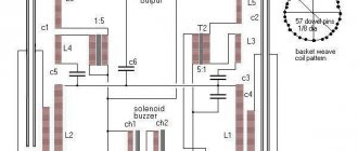
Most of the parts are located on the printed circuit board Fig. 2 . (110 x 42 mm). The board is installed into the case perpendicular to the front panel. All resistor regulators, switches and connectors are located on the front panel. Many parts (in Fig. 2 ) are mounted on their terminals. Switch S1 is a three-way biscuit switch. Only two directions are used. Switch S2 is a two-way toggle switch. All connectors are of the “Asia” type from video equipment. Chokes L1 and L2 are from color modules of old USCT TVs, but you can use any chokes with an inductance of at least 30 μH. Incandescent lamp H1 is an indicator lamp with flexible wire leads (similar to an LED), with a voltage of 6.3V and a current of 20 mA. You can use another lamp with a voltage of 2.5-13.5V and a current of no more than 0.1A.
to set up the generator using a frequency meter and an oscilloscope . In this case, by adjusting resistor R1, a maximum and undistorted alternating sinusoidal voltage is achieved at the generator output, over the entire frequency range (this usually corresponds to an output alternating voltage of 1V). Then, by more precise selection of R4 and R3 (these resistances must be the same), the frequency tuning ranges are set. If insufficiently accurate capacitors C1-C6 are used, it may be necessary to select them or connect “additional” capacitors of smaller capacity in parallel with them. If you don’t have an oscilloscope, you can set up the generator with satisfactory quality using an AC millivoltmeter . You need to set R6 to the position of the maximum output voltage (up in the diagram), connect a millivoltmeter to X1 and adjust R1 so that the millivoltmeter shows somewhere between 0.8 - 1.1V over the entire frequency range. author Ivanov A.
source: “RADIO CONSTRUCTOR”, 3 – 2007, pp. 14-17
Similar
Details
All capacitors must have a voltage of at least 16V. The H1 incandescent lamp is miniature, with a voltage of 13.5V and a current of 0.068 A. You can also use another lamp with a voltage of no less than 12V and no more than 30V and a current of no more than 0.1 A.
Power transformer T1 is used ready-made, from a network adapter with an output voltage of 12V. It has an alternating voltage on the secondary winding of about 9V. In principle, any transformer with an output voltage of about 8-10V and an output current of at least 0.1 A is suitable.
DIY low frequency generators
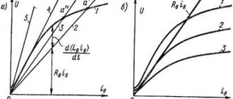
Low frequency generators (LFO) are used to produce undamped periodic oscillations of electric current in the frequency range from fractions of Hz to tens of kHz. Such generators, as a rule, are amplifiers covered by positive feedback (Fig. 11.7, 11.8) through phase-shifting chains. To implement this connection and to excite the generator, the following conditions are necessary: the signal from the output of the amplifier must arrive at the input with a phase shift of 360 degrees (or a multiple of it, i.e. 0, 720, 1080, etc. degrees), and the amplifier must have some gain margin, KycMIN. Since the condition for the optimal phase shift for generation to occur can only be satisfied at one frequency, it is at this frequency that the positive feedback amplifier is excited.
To shift the signal in phase, RC and LC circuits are used, in addition, the amplifier itself introduces a phase shift into the signal. To obtain positive feedback in the generators (Fig. 11.1, 11.7, 11.9), a double T-shaped RC bridge is used; in generators (Fig. 11.2, 11.8, 11.10) - Wien bridge; in generators (Fig. 11.3 - 11.6, 11.11 - 11.15) - phase-shifting RC circuits. In generators with RC circuits, the number of links can be quite large. In practice, to simplify the scheme, the number does not exceed two or three.
Calculation formulas and relationships for determining the main characteristics of RC sinusoidal signal generators are given in Table 11.1. To simplify calculations and simplify the selection of parts, elements with the same ratings were used. To calculate the generation frequency (in Hz), resistance values expressed in Ohms and capacitances - in Farads are substituted into the formulas. For example, let's determine the generation frequency of an RC oscillator using a three-link RC positive feedback circuit (Fig. 11.5). At R=8.2 kOhm; C = 5100 pF (5.1x1SG9 F), the operating frequency of the generator will be equal to 9326 Hz.
In order for the ratio of the resistive-capacitive elements of the generators to correspond to the calculated values, it is highly desirable that the input and output circuits of the amplifier, covered by a positive feedback loop, do not shunt these elements and do not affect their value. In this regard, to construct generator circuits, it is advisable to use amplification stages that have high input and low output resistance.
In Fig. 11.7, 11.9 show “theoretical” and simple practical circuits of generators using a double T-bridge in a positive feedback circuit.
Generators with a Wien bridge are shown in Fig. 11.8, 11.10 [R 1/88-34]. A two-stage amplifier was used as a ULF. The amplitude of the output signal can be adjusted using potentiometer R6. If you want to create a generator with a Wien bridge, tunable in frequency, a dual potentiometer is switched on in series with resistors R1, R2 (Fig. 11.2, 11.8). The frequency of such a generator can also be controlled by replacing capacitors C1 and C2 (Fig. 11.2, 11.8) with a dual variable capacitor. Since the maximum capacitance of such a capacitor rarely exceeds 500 pF, it is possible to tune the generation frequency only in the region of sufficiently high frequencies (tens, hundreds of kHz). The stability of the generation frequency in this range is low.
In practice, switchable sets of capacitors or resistors are often used to change the generation frequency of such devices, and field-effect transistors are used in the input circuits. In all the given circuits there are no elements for stabilizing the output voltage (for simplicity), although for generators operating at the same frequency or in a narrow tuning range, their use is not necessary.