a brief description of
The control cable is used both for connection and for transmitting information about the parameters and status of objects located outside the access zone. Unlike communication wire, it is current-carrying and is used to connect devices with nominal AC voltages up to 660 V or DC voltages up to 1000 V at temperatures from -50 °C to +50 °C. All models must comply with the requirements of GOST 1508-78.
Classification of conductors
The types of connecting products used in the installation of an electrical network are given in GOST 15845-80.
Wires
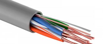
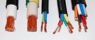
They consist of 1-3 copper cores, enclosed in a braid of PVC, polyethylene or rubber. They are united by common isolation. The cores can be solid or consist of several conductors. Their cross-sectional area is no more than 2.5 mm. Wires are not used for laying underground or where increased safety is required.
Cable
Electrical cables have a more complex design and reinforced insulation. There may be additional filling between the cores, sometimes there is a screen, double braiding. To organize electrical wiring in residential premises, only cables are always used. Some of them are laid underground or by air.
This is a wire with increased flexibility. It is used in devices that must operate in mobile conditions: irons, blenders, electric shavers, etc.
An example is the ShRO cord. Its braid consists of fabric threads, and its flexibility corresponds to class 5.
Most often, such a cord can be seen in household appliances that are subject to movement during operation.
Specifications
Control cables have from 4 to 61 cores. Wires with aluminum conductors are produced only with a nominal cross-section from 2.5 to 10 mm2. Cables with copper conductors can have a cross-section from 0.75 to 6.0 mm2.
Copper and aluminum conductors of control cables must be single-wire. Isolated ones are twisted. Let's allow a core that has up to 4 insulated cores in the center without twisting, if subsequent layers are provided.
The nominal insulation thickness for cores is:
- cross section 0.75; 1.0; 1.5; 2.5 mm2 – 0.6 mm (made of PVC plastic and polyethylene);
- with a cross section of 4.0 and 6.0 mm2 – 0.7 mm (PVC plastic) and 0.6 mm (polyethylene);
- with a cross section of 10 mm2 - 0.9 mm (PVC plastic) and 0.8 mm (polyethylene).
Control cables of the AKVVGz and KVVGz brands must have a filling that provides a round or close to cylindrical shape.
Marking of insulated cores must be color or digital. Color markings are made in one color or with stripes. When marking digitally, the distance between numbers should be no more than 35 mm.
In AKVBBShV, KVBbShV and KVKbShV, a separating layer with a thickness of at least 0.5 mm is applied to the stranded conductors - made of polyvinyl chloride plastic or electrical insulating films. In KPVGE, AKVVGE, KVVGE, AKVVGEng, KVVGEng, a foil screen is placed over the twisted cores, providing an overlap of at least 20%.
The nominal shell thickness depends on the diameter. Its value should be as follows:
| Cable diameter, mm | Nominal shell thickness, mm |
| up to 6.0 | 1,2 |
| 6,0-15,0 | 1,5 |
| 15,0-20,0 | 1,7 |
| 20,0-30,0 | 1,9 |
| 30,0-40,0 | 2,1 |
| over 40.0 | 2,3 |
The control cables must withstand an alternating voltage of 2500 V at a frequency of 50 Hz for 5 minutes.
The insulation resistance of the conductors, recalculated per 1 km of length at a temperature of 20 ° C, must be at least 300 MOhm - with polyethylene insulation and 6 MOhm - for cables with polyvinyl chloride insulation.
Marking of cable lines.
Wires and cables laid in boxes and on trays must be marked at the beginning and end of the trays and boxes, as well as at the points where they are connected to electrical equipment, and the cables, in addition, also at route turns and branches. Each cable line must be marked and have its own number or name. Labels must be installed on exposed cables and cable joints. Tags must be secured to the cables with nylon thread or galvanized steel wire with a diameter of 1 - 2 mm, or plastic tape with a button. The place where the tag is attached to the cable with wire and the wire itself in damp rooms, outside buildings and in the ground must be covered with bitumen to protect it from moisture. On hidden cables in trenches, tags are installed at the end points and at each coupling. Tags should be used: in dry rooms - made of plastic, steel or aluminum; in damp rooms, outside buildings and in the ground - made of plastic. Designations on tags for underground cables and cables laid in rooms with a chemically active environment should be made by stamping, punching or burning. For cables laid in other conditions, markings may be applied with indelible paint. On cables laid in cable structures, tags must be installed at least every 50 - 70 m, as well as in places where the direction of the route changes, on both sides of passages through interfloor ceilings, walls and partitions, in places where cables enter (exit) into trenches and cable structures. On hidden cables in pipes or blocks, tags should be installed at the end points at the end couplings, in the wells and chambers of the block sewer system, as well as at each connecting coupling.
Classification
Based on the material of the conductor, control cables are divided into those made from copper, aluminum or copper-aluminum wire.
The insulation material can be rubber, polyvinyl chloride plastic, self-extinguishing polyethylene or low-density polyethylene, vulcanized polyethylene.
Based on the shell material, rubber products are distinguished from non-flammable rubber and polyvinyl chloride plastic.
The shape of the wires can be round or flat.
Based on the type of protective cover, cables are divided into models with a cover made of lead, aluminum, and corrugated steel tape.
Based on the type of armor and protective coverings or the area of use, 4 types are distinguished. The former are used indoors, in channels and tunnels, provided that the product is not subject to significant tensile forces. Their armor consists of two steel strips treated with an anti-corrosion coating, one profiled strip or two galvanized strips.
The latter are used indoors, in channels, tunnels in the complete absence of mechanical influences.
Still others are used in the ground (trenches), and they should not be subject to significant tensile forces. Their armor consists of two steel strips with a protective cover on the outside - a PVC hose.
The fourth ones are used for laying in channels and in the ground, if they are not subject to significant tensile forces. The armor is made of two galvanized wires and has an outer protective cover or PVC hose.
These cables are intended for the transmission and distribution of electrical energy in stationary installations at rated voltages from 1 to 35 kV with a frequency of 50 Hz in networks with an isolated neutral, as well as in networks with a grounded neutral and direct voltage networks.
Power cables are available in one-, two-, three- or four-core versions. The conductors can be copper or aluminum, round, sector or segment shaped. Voltage cables 1. 10 kV are usually three-phase. The use of two- and four-core cables is possible only at a voltage of 1 kV. Cables with impregnated paper insulation
can be single-, three- and four-core, and single- and four-core cables are made only for a voltage of 1 kV, and three-core cables can be for 1;
3; 6 and 10 kV. Main features of voltage cables 1. 10 kV is the absence of insulation screens and the use of sectored conductors, which makes it possible to reduce their outer diameter by 15.25%, as well as weight and cost. For voltages of 20 and 35 kV, cable designs
with separately shielded conductors and a radial electric field are used.
In domestic practice, cables with separately leaded conductors are used. You can determine which group and type a given cable or wire belongs to by its brand, which is a certain set of letters and numbers. The letters usually indicate the main design features of the cable or (sometimes) its purpose. The numbers can indicate (for example, for a power cable) the number and cross-sectional area of the cable phases or the voltage class for which this cable is intended. For power cables
with impregnated paper insulation for voltage 1;
3; 6; 10; 20 and 35 kV, the letter “A” at the beginning of the brand means that their core is made of aluminum, but if this letter is missing, this means that copper was used as the core material. To increase flexibility, large-section cores are made multi-wire, that is, from several dozen individual wires that are twisted around a central core to give greater geometric stability to the structure. It also reduces the electrical resistance of the conductor by reducing the skin effect and proximity effect of currents in adjacent cables (which are especially noticeable at high frequencies). To increase the fill factor (the ratio of the cross-sectional area of a copper conductor to the geometric area of its cross-section) the cores can be made compacted. To do this, after twisting, they are subjected to compressive forces in the radial direction. The characteristics of various types of conductors are presented in table. 1. The required core cross-sections
are mainly determined by the current for which the cable is designed, its design and installation method.
The insulation of power cables
consists of cable paper strips impregnated with an oil rosin composition. Each phase of the cable is first insulated separately, and then a common belt insulation is applied over the twisted insulated cores. The gaps between the insulated conductors are filled with paper bundles.
| Table 1 Characteristics of various types of conductors Core type | Nominal core cross-section, mm2 | |||
| round | shaped | |||
| copper | aluminum | copper | aluminum | |
| Single wire | 1.50 | 25.240 | 25.50 | 25.240 |
| Stranded | 16.240 | 25.240 | 25.240 | 25.240 |
The electric field in cables with belt insulation has a complex appearance. Since the power lines in some areas of the cable cross-section are not perpendicular to the layers of paper, a tangential component of the electric field strength appears in the insulation. If we take into account that the electrical strength of insulation in the direction perpendicular to the layers of paper insulation is 8-10 times greater than along these layers, it becomes obvious that the most dangerous place in the insulation is the interfacial fillings. Thus, the thickness of the insulation between phases should be approximately 36% greater than the thickness of the insulation between the cores and the sheath. Thus, for cables with a voltage of 6 kV, the thickness of the phase insulation is 2 mm, and the belt insulation is 0.95 mm; for cables with a voltage of 10 kV - 2.75 and 1.25 mm, respectively. The insulation material is not indicated in the marking of a cable
with cable paper insulation, but the composition impregnating the paper may be indicated.
The fact is that the special cable paper used as insulation, made from sulphate cellulose, in its dry form does not have a high enough electrical strength due to the large number of pores filled with air (up to half the volume of the paper). This explains the development of ionization processes at low voltages. If air is removed, for example, by impregnating paper with special viscous oil-rosin compounds, its electrical strength increases several (up to 10) times. However, such cables cannot be laid on routes with a level difference of more than 15 m due to the fact that in the lower sections of the route, where the impregnating composition will flow, the oil pressure increases sharply. This may cause the metal sheath to rupture. The flow of the composition occurs mainly along the spaces between the wires in twisted stranded strands and along the gaps between the metal sheath and the insulation, as well as (to a lesser extent) inside the paper insulation. At the same time, in the upper sections of the route the electrical strength of the cable will decrease due to the appearance of air gaps in the insulation. The drainage of the impregnating composition can be reduced by using stop couplings when connecting the construction lengths of the cable, reducing the volume of the impregnating composition and increasing its viscosity. Stop couplings, which limit the movement of the impregnating composition from one section of the cable line to another, make it possible to increase the difference in cable laying levels. However, for steeply inclined and vertical routes their use is not always effective. The use of cables with depleted impregnated insulation significantly increases the permissible value of the difference in laying levels. The electrical strength of such cables is lower than cables of conventional design, so they are produced for voltages no higher than 6 kV. For installation on vertical and steeply inclined routes without limiting the difference in levels, there is a special group of cables with paper insulation impregnated with a non-drip compound. This impregnating composition has a high viscosity, which virtually eliminates its movement along the cable. Cables with insulation impregnated with a non-drip compound are produced for voltages of 6, 10 and 35 kV in single-core and three-core versions, and their designs are practically no different from those of conventional cables. The brand of such cables begins with the letter “C”. In the designation of cables with depleted insulation, the letter “B” is added through a hyphen. The insulation thickness is determined by the voltage class for which the cable is designed. It also depends on the outer diameter of the core (its cross-section), which is explained by the inversely proportional dependence of the electric field strength in the insulation at the surface of the core on its diameter. The letter “C” in the cable designation
indicates the presence of a lead sheath.
The material for such shells can be either lead or lead-antimony alloys, which have increased mechanical strength and vibration resistance compared to pure lead. Cables with impregnated paper insulation use only a metal sealed sheath. The use of polyethylene, polyvinyl chloride or other polymers, despite their relatively low cost, is impossible, since moisture will diffuse into the insulation through such a sheath over time, which can lead to cable breakdown. Aluminum, which is not as scarce and heavy as lead, can also be used as a shell material. In this case, the cable designation will include the letter “A”. However, since aluminum has less resistance to electrochemical corrosion, such a shell must be protected with a polymer coating; and since the aluminum sheath has increased rigidity, for cables of large cross-sections it must be corrugated to increase flexibility and ensure installation, eliminating possible damage due to bending. In addition, aluminum shells are 2-2.5 times stronger than lead shells and more resistant to vibration. Thus, at elevated temperatures and under the influence of vibration loads, spontaneous growth of lead crystals is observed, which leads to a deterioration in its mechanical properties and the formation of cracks. With prolonged application of tensile forces, the strength of the lead sheath decreases and it stretches. Because of this, in the lower sections of vertical and steeply inclined routes, irreversible processes of stretching of the lead sheaths of oil-filled cables are observed, which can lead to their rupture. The high electrical conductivity of aluminum makes it possible to use shells made of it as a screen to protect the cable from external electrical influences, especially at high frequencies or when the shell is used as a neutral core. Metal shells are quite hermetically sealed, but cannot always provide the necessary protection from mechanical influences. Thus, when laid in the ground, the cable may be subject to significant radial impacts. In this case, usually armor made of two steel strips with a thickness of 0.3-0.8 mm is applied over the shell in small increments. To prevent the armor from damaging the lead or aluminum sheath, it is laid on a cushion, which consists of alternating layers of cable yarn and cable paper impregnated with a bitumen composition. To prevent corrosion of the steel strips, an outer cover is applied over the armor. This type of protective cover is marked with the letter “B”, which, depending on the type of pillow and outer cover, may have a corresponding index. If, during installation, significant tensile forces are applied to the cable, from which armor made of steel tapes applied at small intervals cannot protect, galvanized steel wires with a diameter of 4 or 6 mm are used. Wire armor is applied in small increments in a continuous layer, and it is able to withstand significant tensile forces. This design also provides a cushion under the armor and an outer cover. Such a protective cover is marked with the letter “K” with an index indicating the design features of the cushion under the armor and the outer cover. The outer covering of cables can be made of fibrous materials or plastic. The fibrous outer cover consists of a layer of bitumen compound, impregnated cable yarn, another layer of bitumen compound and chalk (or crushed mica) to prevent the cable turns from sticking together on the drum. The plastic outer cover of the cables consists of a layer of bitumen composition, polymer tapes and polyethylene (PE) or PVC hose. PVC hoses placed over the armor of power cables ensure their non-flammability. PE hoses, which have greater moisture resistance and lower water permeability, are used to protect aluminum casings from corrosion. If the cable is laid in the air,
there is no need to protect it from mechanical influences, but in this case the metal sheath must be protected from atmospheric influences.
The corresponding protective cover is designated by the letter “G”. Due to their greater mechanical strength, cables with aluminum sheaths can be made unarmoured. Let us give several examples of marking of power cables
with impregnated paper insulation for voltages of 1.10 kV, the design of which is shown in Fig.
1: SG - cable with a copper core, lead sheath, without protective cover; ASG - the same, but with an aluminum core; SKl - cable with a copper core and armor made of round tinned wires (used for underwater installation); TSAABShv - a cable with insulation impregnated with a non-draining compound, an aluminum core and sheath, as well as armor made of two steel tapes, covered with a PVC hose (used for laying in the ground); SBL-V - cable with copper conductors, armor made of two tinned steel strips and lean-impregnated insulation (used for laying in the ground with large differences in height along the route). Rice. 1. Design of a three-core cable with belt insulation: 1 - current-carrying core; 2 - core insulation; 3 - waist insulation; 4 - interphase fillings; 5 - lead or aluminum sheath; 6 — pillow under armor; 7 — armor made of two steel strips; 8 - outer protective cover Power cables
for voltages of 20 and 35 kV have a conductive screen and a metal sheath on top of the insulation of each core.
Cables for voltage 20 kV are made single-core with sections 25.400 mm2 and three-core (in separate metal sheaths) with sections 25.185 mm2. Cables for a voltage of 35 kV are made single-core with sections of 120.300 mm2 and three-core (in separate metal sheaths) with sections of 120 and 150 mm2, and cables with armor made of round wires - with a cross-section of 150 mm2. In cables for a voltage of 35 kV, conductors with small cross-sections are not used, since in this case the thickness of the insulation turns out to be unreasonably large, i.e., the use of such cables becomes uneconomical. A screen of semiconducting tapes is placed on top of the round copper or aluminum conductors in these cables, then impregnated paper insulation, again a screen and a lead sheath. The cable design for underwater installation is shown in Fig. 2. The insulation thickness in 20 kV cables is 6. 7 mm depending on the cross-section of the core, and in 35 kV cables - does not exceed 9 mm. The thickness of the lead sheath of these cables depends on the cross-section of the core and is 1.4-2.8 mm. (Aluminum sheaths for such cables were not used due to their rigidity.) Separately leaded conductors are twisted and the spaces between them are filled with impregnated cable yarn or glass yarn. On the outside, fabric tape or cable yarn is applied to the twisted phases with filling, and then protective covers. Here are examples of marking power cables for voltages of 20 and 35 kV: OSB - power cable with three separately insulated and leaded copper conductors and tape armor; AOSK is a power cable with three separately insulated and leaded aluminum conductors and armor made of round wires. Abroad, so-called D-cables have become widespread, in which three insulated and shielded cores are twisted together and placed in a common lead or corrugated aluminum sheath. The radial field in them is provided by a screen made of copper tapes, applied over the insulation of each core. Recently, D-cables with sector conductors have become widespread. Rice. 2. Design of a three-core cable with separately leaded conductors for underwater installation: 1 - current-carrying conductor; 2, 4 — screen made of semiconducting paper; 3 - impregnated paper insulation; 5 - lead sheath; 6 - filling made of impregnated cable yarn; 7—wire armor; 8 - outer protective cover The production of D-cables, which have a slightly smaller cross-sectional area, requires less materials, however, cables with separately leaded conductors are more flexible, contain a smaller amount of impregnating composition and provide better heat dissipation conditions.
Marking
The marking of the control cable serves to express information about it: its purpose, the material from which the conductors are made, insulation, sheath and its design, type of armor and cover, number of conductors and their cross-section. Marking is carried out using letters.
The purpose is designated by the letter K - control.
In the brands of copper control cables, the material of the conductor is not indicated. Aluminum is designated by the letter A, aluminum-copper by the letters AM.
The insulation material is designated as follows: rubber - R, polyvinyl chloride plastic compound - B, low-density polyethylene - P, self-extinguishing polyethylene - Ps.
Shell construction material: corrugated steel tape – St, rubber – R, flame retardant rubber – N, polyvinyl chloride plastic compound – V.
Round wires are not designated, flat wires are designated by the letter P.
Wire marking according to GOST
Letter designations
- Material: copper – no, aluminum “A”; For cables: sheath material, for wires: “P” - wire, “PP” - flat wire, there are two or three wires;
- Insulation material: R – rubber, P – polyethylene, N – nayrite, V – polyvinyl chloride;
- For cables – protective cover design.
Digital values
- Number of cores (if not, then the product is single-core);
- Cross-sectional area;
- Highest network voltage;
There is a standard range of cross-sectional areas, from which the desired value is selected according to the permissible current load, based on its operating conditions.
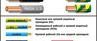
Color coding of conductors
It was not produced before. Color coding facilitates installation and provides protection against electric shock. Therefore, GOST 50462-2009 establishes its mandatory presence. In some cases, color marking is combined with a letter designation.
In cables, each core has its own color. The neutral is always blue (cyan) and the ground wire is yellow-green. The phase can have different colors, but black, brown and gray are preferred.
According to the functional purpose of multi-core cables, the generally accepted colors are in accordance with the following table:
In a positive current network, the positive pole is always indicated by brown or red, and the negative pole by gray (black) colors. The middle and grounded conductors are blue.
Power aluminum cable
Power cables and wires with aluminum conductors are used in high voltage power lines.
At high voltage values, the throughput does not depend on the resistance of the current-carrying conductors. At low voltages, this factor reduces the throughput. Aluminum power cable is widely used due to its low cost and small overall weight. Accordingly, these mentioned advantages determine its superiority over similar conductors made of copper conductors. When there are operating restrictions in terms of weight and the need for large diameter cable lines, aluminum conductors are used. Despite the presence of a number of limitations and disadvantages, this does not reduce the share of its use in various fields of human activity and production. First of all, during operation, you need to focus on the effective use of the positive qualities of the product.
In low voltage power lines, aluminum power cable has also found its application; the high resistance is compensated by increasing the cross-sectional area of the conductors.
In residential premises, it is preferable not to lay cables with current-carrying conductors made of aluminum, because aluminum connections are short-lived, unlike similar copper conductors. It is strictly prohibited to connect copper and aluminum conductors to each other. The ion exchange that occurs as a result of the connection worsens the properties of aluminum, which can lead to an emergency. When connecting, special lugs or intermediate conductors made of tin are used.
The cost of power cables with aluminum conductors varies depending on the LME/LME (London Metal Exchange) price data.
Marking of foreign cables
The color marking of cable cores produced abroad is slightly different: the phase wire is brown, the ground wire is black, and the neutral wire is white.
The alphanumeric designation is the same in all countries:
| Product type | View | Designation |
| Cables | power | N |
| agreed type | N | |
| Rated voltage | 300/300 | 0,3 |
| 300/500 | 0,5 | |
| 450/750 | 0,7 | |
| Core material | copper | Cu or absent |
| aluminum | A, Al | |
| Insulation material | Different types of PVC | Y,PV,V |
| Various tires | G, R, N, S | |
| Different types of polyethylene | 2Y, 02Y, 02YS, XLPE, 2X | |
| Semiconducting layer in power cables | semiconducting layer | N |
| Screen | Copper concentric | C, S |
| Made from aluminum foil | A | |
| Water protection | F | |
| Without filler in aluminum shell | FY(2Y), (L>2Y | |
| Outer shell | PVC | V |
| Rubber | R | |
| Polychloroprene | N, Y, PVC | |
| Polyethylene | 2Y | |
| Armor | Flat steel strip | B, S.T.A. |
| Round steel wire | S.W.A. |