Square Pulse Generator
Greetings, homemade radio amateurs!
In the course of amateur radio activities, it is often necessary to conduct various experiments that require signals of different shapes - for example, sine wave, triangle, saw, rectangular pulses - the latter are used most often, for example, PWM is based on them - pulse width modulation. There are various devices on sale that allow you to generate signals of various shapes, frequencies and amplitudes; most often they are quite expensive and are used where experiments need to be carried out regularly, for example, in laboratories. For one or two times it is not necessary to buy a special device, because such a generator, which will create rectangular pulses of adjustable frequency and duration, can be built in just a couple of hours with your own hands, using only the most accessible and cheap elements that a radio amateur has at hand. There can be quite a few options for circuits of such generators, but this circuit is based on a pair of logic chips, its advantages include the ability to adjust the frequency from 5 Hz to 1 kHz - this is enough for many applications, and there is also an additional duty cycle (duration) adjustment of the pulse.
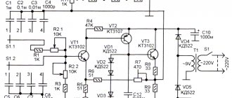
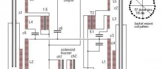
The schematic diagram is shown in the picture above. As you can see, only 6 2I-NOT logic elements are involved. Each such element has two inputs and one output; the prefix “NOT” means that the output signal is inverted. Each such element works as follows - if a logical unit is applied to both inputs (i.e. the voltage is above a certain threshold), then there will be no voltage at the output (since there is a “NOT” prefix), but if at least one input , or there will be a logical zero on two at once, then the output of the microcircuit will be a voltage close to the supply voltage. A logical zero is considered to be a voltage close to zero, i.e. no tension. If you connect these elements in a certain way, adding a capacitor and a resistor, you can get a rectangular pulse generator - the first three elements form just that. As you can see, the resistor is set to variable; with its help, the frequency will be adjusted within a wide range. A 1 kOhm constant resistor in series with it serves to limit the extreme position so that in the extreme position the resistor does not become a jumper and interfere with the operation of the circuit. For convenience, you can install two variable resistors in series, for example, one of 1 MOhm, as in the diagram, for rough tuning, and with it a second one of 100 kOhm, with which the frequency can be set more precisely. The circuit does not provide any display of the current frequency, so it is very convenient to use it in conjunction with a frequency meter, for example, the simplest one with several transistors, the circuit of such a frequency meter was described in one of the previous articles, the frequency meter will display the current output pulse frequency. Another option is to install a variable resistor on the front panel of the case and draw a frequency scale around it, having previously calibrated it using the same frequency meter or oscilloscope. Capacitor C3 is also a frequency-setting capacitor; you can experiment with its value by changing the range of frequencies controlled by the resistor. An inverter is assembled on the 4th logical element so that the rectangular pulses from the generator have a positive amplitude. If you close the two inputs of the 2I-NOT element, it simply becomes an inverter. Using the same logic elements 5 and 6, a part of the circuit is assembled that allows you to adjust the duty cycle, that is, the pulse duration - this is achieved using the operation of a one-shot device. Resistor R3 is also variable, with its help smooth adjustment occurs. Capacitor C4 is also directly involved in the operation of the monovibrator; you can experiment with its value by changing the adjustment range. A ready-made rectangular pulse signal is removed from the output of the 6th logical element; after all the necessary adjustments, it can be used. But it is preferable to first pass this signal through a buffer (emitter follower) on a transistor; this stage has a high input resistance and a low output, decouples the output of the microcircuit from the load connected to the generator. Any low-power NPN transistor can be used as a transistor, be it the popular BC457, KT3102, KT315 or their analogues. The signal is removed from the emitter of the transistor and goes to the output through a 100 Ohm resistor - directly to where rectangular pulses are required. This resistor does not greatly increase the output resistance, but it protects the transistor from a short circuit to the load - the output can even be directly shorted to ground, this will not damage the circuit and nothing will burn out. However, the maximum output current of such a generator circuit is not large and amounts to only a few units, a maximum of tens of milliamps - if the generator needs to switch a powerful load, for example, coils or solenoids, you should additionally install a power stage on a powerful field-effect transistor.
As you know, logic chips can be of the TTL type - transistor-transistor logic, and CMOS - complementary logic on MOS transistors, that is, field-effect ones. TTL is characterized by low input impedance and higher power consumption, while CMOS, on the contrary, has a high input impedance and consumes negligible current. Very often, the same microcircuits, with the same operating logic, can be made using both TTL and CMOS technology, for example, the K561LA7 microcircuit (imported analogue of CD4011) required for this generator corresponds to CMOS, and its TTL analogue is K155LA3. Both microcircuits contain 4 2I-NOT elements, they also have the same pinout and are completely interchangeable in this circuit. The only caveat is that in the case of using K155LA3, the resistance of the variable resistor R3 should be reduced to 2 kOhm, this is due to the low input impedance of TTL microcircuits. The pinout of the microcircuits can be seen in the photo above.
The supply voltage of the circuit depends on the type of microcircuit used, for example, if K155LA3 is used, then the supply voltage should be equal to 5V - in this case it is very convenient to use any USB port for power supply, for example, from a computer, Power Bank or network adapter-charging, current consumption The entire circuit is small, so the power of the power supply will not be critical. When using the K561LA7, the range of supply voltages is quite wide - from 5 to 15V, so you can use many more different source options for power supply, for example, various network adapters from household devices. The current consumption with this microcircuit is even less, so you can use a crown battery as a source without any problems - in this case, the generator will become completely autonomous. Please note that the microcircuits used contain 4 logical elements inside, but the circuit requires 6 of them, so you will have to use two microcircuits at once, one of them will have two unused elements - it is advisable to connect the extra pins to the power supply negative. But if you wish, you can get by with one microcircuit, if you remove the block for adjusting the pulse duration on elements 5 and 6 and remove the signal from the output of the 4th element, the duty cycle in this case will be equal to 50%, that is, the pulse duration is equal to the pause duration. The amplitude of the output pulses will be equal to the supply voltage. Thus, when using the K561LA7 microcircuit, you can adjust the supply voltage from 5 to 15V - the amplitude of the output signal will change in the same way. Capacitors C1 and C2, one of them is polar electrolytic and the second is ceramic, are located along the power circuit to filter out interference - you should not neglect them so that the output signal is smooth and without distortion. The circuit does not require configuration and, when voltage is applied, it immediately starts working, provided that it is installed correctly. It wouldn’t hurt to install the finished board in the case for ease of use, and bring the variable resistor knobs out for adjustments. Happy building! Source
Circuits of simple pulse generators
Pulse generators are an important component of many radio-electronic devices. The simplest pulse generator (multivibrator) can be obtained from a two-stage ULF (Fig. 6.1). To do this, simply connect the amplifier's input to its output. The operating frequency of such a generator is determined by the values of R1C1, R3C2 and the supply voltage. In Fig. 6.2, 6.3 show multivibrator circuits obtained by simply rearranging the elements (parts) of the circuit shown in Fig. 6.1. It follows that the same simple diagram can be depicted in different ways.
Rice. 6.1
Rice. 6.2
Practical examples of using a multivibrator are shown in Fig. 6.4, 6.5.
In Fig. Figure 6.4 shows a generator circuit that allows you to smoothly redistribute the duration or brightness of the LEDs connected as a load in the collector circuit. By rotating the R3 potentiometer knob, you can control the ratio of the durations of the LEDs of the left and right branches. If you increase the capacitance of capacitors C1 and C2, the generation frequency will decrease and the LEDs will begin to blink. As the capacitance of these capacitors decreases, the generation frequency increases, the flickering of the LEDs will merge into a continuous glow, the brightness of which will depend on the position of the potentiometer R3 knob. Based on such a circuit design, various useful structures can be assembled, for example, a brightness control for an LED flashlight; toy with blinking eyes; a device for smoothly changing the spectral composition of the radiation source (multi-colored LEDs or miniature light bulbs and a light-summing screen).
Rice. 6.3
Rice. 6.4
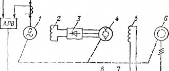
The variable frequency generator (Fig. 6.5) designed by V. Tsibulsky allows you to obtain sound that smoothly changes over time in frequency [P 5/85-54]. When the generator is turned on, its frequency increases from 300 to 3000 Hz in 6 seconds (with a capacitor capacity of SZ 500 μF). Changing the capacitance of this capacitor in one direction or another accelerates or, conversely, slows down the rate of change in frequency. You can smoothly change this speed with variable resistance R6. In order for this generator to act as a siren, or to be used as a sweeping frequency generator, it is possible to provide a circuit for forced periodic discharge of the SZ capacitor. Such experiments can be recommended for independent expansion of knowledge in the field of pulse technology.
Rice. 6.5
Rice. 6.6
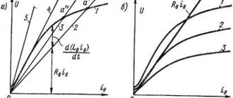
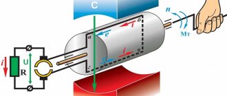
A controlled square pulse generator is shown in Fig. 6.6 [R 10/76-60]. The generator is also a two-stage amplifier covered by positive feedback. To simplify the generator circuit, it is enough to connect the emitters of the transistors with a capacitor. The capacitance of this capacitor determines the operating frequency of generation. In this circuit, a varicap is used as a voltage-controlled capacitance to control the generation frequency. An increase in the blocking voltage on the varicap leads to a decrease in its capacity. Accordingly, as shown in Fig. 6.7, the operating frequency of generation increases.
Rice. 6.7
The varicap, as an experiment and to study the operating principle of this semiconductor device, can be replaced with a simple diode. It should be taken into account that germanium point diodes (for example, D9) have a very small initial capacitance (of the order of several pF), and, accordingly, provide a small change in this capacitance depending on the applied voltage. Silicon diodes, especially power diodes designed for high current, as well as zener diodes, have an initial capacitance of 100 ... 1000 pF, so they can often be used instead of varicaps. Pn junctions of transistors can also be used as varicaps, see also Chapter 2.
To control the operation, the signal from the generator (Fig. 6.6) can be applied to the input of the frequency meter and the tuning limits of the generator can be checked when the control voltage changes, as well as when changing a varicap or its analogue. It is recommended that the results obtained (control voltage values and generation frequency) when using different types of varicaps be entered into a table and displayed on a graph (see, for example, Fig. 6.7). Note that the stability of generators based on RC elements is low.
Rice. 6.8
Rice. 6.9
In Fig. 6.8, 6.9 show typical circuits of light and sound pulse generators made on transistors of various conductivity types. Generators are operational in a wide range of supply voltages. The first of them produces short flashes of light with a frequency of one Hz, the second produces pulses of sound frequency. Accordingly, the first generator can be used as a beacon, a light metronome, the second - as a sound generator, the oscillation frequency of which depends on the position of the potentiometer R1. These generators can be combined into a single unit. To do this, it is enough to turn on one of the generators as a load of the other, or in parallel with it. For example, instead of a chain of LEDs HL1, R2 or in parallel with it (Fig. 6.8), you can turn on the generator according to the circuit in Fig. 6.9. The result will be a periodic sound or light and sound signaling device.
The pulse generator (Fig. 6.10), made on a composite transistor (p-p-p and p-p-p), does not contain capacitors (a piezoceramic emitter BF1 is used as a frequency-setting capacitor). The generator operates at a voltage from 1 to 10 B and consumes a current from 0.4 to 5 mA. To increase the sound volume of a piezoceramic emitter, it is tuned to the resonant frequency by selecting resistor R1.
Rice. 6.10
Rice. 6.11
In Fig. Figure 6.11 shows a rather original generator of relaxation oscillations, made on a bipolar avalanche transistor.
The generator contains as an active element a transistor of the K101KT1A microcircuit with inverse switching in the mode with a “broken” base. The avalanche transistor can be replaced with its analogue (see Fig. 2.1).
Devices (Fig. 6.11) are often used to convert the measured parameter (light intensity, temperature, pressure, humidity, etc.) into frequency using resistive or capacitive sensors.
When the generator is operating, a capacitor connected in parallel to the active element is charged from the power source through a resistor. When the voltage on the capacitor reaches the breakdown voltage of the active element (avalanche transistor, dinistor, or similar element), the capacitor is discharged into the load resistance, after which the process is repeated with a frequency determined by the constant of the RC circuit. Resistor R1 limits the maximum current through the transistor, preventing its thermal breakdown. The timing circuit of the generator (R1C1) determines the operating range of generation frequencies. Headphones are used as an indicator of sound vibrations for quality control of generator operation. To quantify the frequency, a frequency meter or pulse counter can be connected to the generator output.
The device is operational in a wide range of parameters: R1 from 10 to 100 kOhm (and even up to 10 MOhm), C1 - from 100 pF to 1000 μF, supply voltage from 8 to 300 V. The current consumed by the device usually does not exceed one mA. It is possible for the generator to operate in standby mode: when the base of the transistor is shorted to ground (common bus), generation is interrupted. The converter-generator (Fig. 6.11) can also be used in the mode of a touch key, a simple Rx and Cx meter, a tunable wide-range pulse generator, etc.
Pulse generators (Fig. 6.12, 6.13) are also made on avalanche transistors of the K101KT1 microcircuit of the p-p-p type or K162KT1 of the p-p-p type, dinistors, or their analogues (see Fig. 2.1). The generators operate at a supply voltage above 9 B and produce a triangular voltage. The output signal is taken from one of the terminals of the capacitor. The input resistance of the cascade following the generator (load resistance) must be tens of times greater than the value of resistance R1 (or R2). A low-resistance load (up to 1 kOhm) can be connected to the collector circuit of one of the generator transistors.
Rice. 6.12
Rice. 6.13
Rice. 6.14
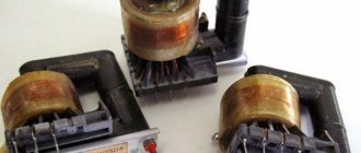
Quite simple and often encountered in practice pulse generators (blocking generators) using inductive feedback are shown in Fig. 6.14 [A. With. USSR 728214], 6.15 and 6.16. Such generators are usually operational over a wide range of supply voltage changes. When assembling blocking generators, it is necessary to observe the phasing of the terminals: if the “polarity” of the winding is connected incorrectly, the generator will not work.
Rice. 6.15
Rice. 6.16
Such generators can be used when testing transformers for the presence of interturn short circuits (see Chapter 32): such defects cannot be detected by any other method.
Literature: Shustov M.A. Practical circuit design (Book 1), 2003