A transformer is a device that passes electric current through itself, changing its characteristics. Almost no electrical or electronic device can do without this device. Energy systems and substations of any size necessarily include various types of transformers.
3 phase power transformer
Story
In the first half of the 19th century, the English physicist Faraday conducted numerous experiments with electricity. As a result of experiments, he discovered such a phenomenon as electromagnetic induction. On August 29, 1831, the scientist described in his diary the result of his research in this direction.
2 copper wires 150 mm and 180 mm long were wound on an iron ring ø 150 mm and 20 mm thick. When a galvanic battery was connected to one winding at the terminals of another conductor, the galvanometer recorded static voltage. This is how the first transformer prototype appeared.
The French mechanic Ruhmkorff made the first induction coil in 1848. It gave an idea of what a transformer is. In 1872, a professor at Moscow University, Stoletov, developed the theory of the hysteresis loop and also substantiated the domain structure of the ferrite core.
November 30, 1876 is considered the date of invention of the AC transformer. On this day, a patent for this invention was issued to the famous Russian physicist Pavel Nikolaevich Yablochkov. The device consisted of an open core with two windings.
The device, invented by Hungarian engineers in 1885, was already a device with a closed magnetic circuit. Since then, cores began to be made from individual steel sheets. The devices began to be placed in vessels filled with oil. This was followed by various improvements to the current conversion design. Edison's engineers, the great Nikola Tesla, Russian, English and German scientists had a hand in this.
Modern transformers are devices designed to deliver electricity with specified characteristics to the consumer.
Features of transformers
Transformers are now used in a wide variety of electrical systems. It is simply impossible to describe all possible installation locations for such equipment; suffice it to say that transformers are installed in all cases where it is necessary to measure voltage parameters and control power in the electrical network. Various electrical devices can receive power from transformers.
In certain cases, transformer equipment can be used as low- or high-power power devices to conduct tests on an electrical system without interrupting the power supply. Installed transformer equipment may require professional electrical measurements, which must include the calculation of the current transformation ratio.
Basic principles of operation
How it works and how to choose a current transformer
The definition of a voltage converter is based on two operating principles:
- Electromagnetism. Changing in a certain time interval, the current creates a changing magnetic field.
- Electromagnetic induction. The passing magnetic current through the secondary winding excites an electromotive force (EMF) in it.
Faraday's law
Electromagnetic induction causes an electric current in a closed circuit during a change in the magnetic flux passing through the area of that circuit.
Faraday's law explains the direct proportional dependence of EMF on the rate of change of magnetic flux. This dependence is reflected by the formula of the law of electromagnetic induction:
Faraday's law formula
- EMF – induction in the circuit;
- ∆Ф – magnetic flux value;
- ∆t – time period.
Important! The minus in the formula of Faraday's law is an adjustment to the expression proposed by the Russian scientist Lenz. The sign “—” means that the induced current in a limited circuit is aimed at preventing a change in the magnetic flux.
Ideal Transformer Equation
Direct electric current with changed parameters into electrical circuits or a certain area of an electronic circuit - which is what transformers are used for. An ideal transformer is a device that does not incur losses due to hysteresis, eddy currents and energy dissipation by windings.
In an ideal device, the powers of both windings are equal. The electric flux, passing through the primary coil, is converted into a magnetic flux, which, in turn, is converted into the emf of the secondary circuit.
What an ideal transformer does can be expressed by the following expression:
P1 = I1U1 = P2 = I2U2,
Where:
- P1 – instantaneous power of the primary circuit;
- P2 – instantaneous power of the secondary winding.
By converting both products of force and current into ratios, we obtain the mathematical definition of an ideal transformer:
U2/U1 = I1/I2 = n,
where n is the transformation coefficient.
Model of a real transformer
The real model of the transformer differs from the ideal design of the device in the following ways:
- Presence of non-zero no-load current;
- The emergence of containers;
- Nonlinear magnetization curve.
Non-zero no-load current
The windings of a real transformer, together with the core plates, represent a magnetoelectric system, where a magnetic field voltage vector circulates along its circuit, equal to the total current inside this circuit.
All types of operating transformers, when switched on without load, experience surges in the primary current. This phenomenon is called non-zero no-load current. When calculating the protection of converter devices, a comparison is made between the actual and ideal shifts of the currents of the two windings. The difference between the angles of these shifts is called the error angle. This indicator is taken into account when determining the class of devices, especially in those models that are designed to work in energy metering systems.
The emergence of containers
Conductors with a dielectric separating material provoke the appearance of parasitic capacitances between the windings, their layers and turns. Thanks to them, high-frequency interference penetrates from the primary coil to the secondary winding. The theoretical values of equivalent capacities are introduced into the calculations of the characteristics of devices. This is done in order to sharply reduce the risk of such negative phenomena as the occurrence of longitudinal and transverse tanks.
Nonlinear magnetization curve
Ferrite transformer cores are found in most types of voltage converters. By achieving a large EMF in the secondary windings, an extremely nonlinear magnetization characteristic is obtained. Accordingly, inductance also takes on a nonlinear character.
As a result, a ferroresonant mode is created, in which there is a risk of failure of the voltage converter. Excessive heating of the magnetic circuit occurs, which necessitates the need to cool the device.
Note! To dampen accompanying eddy currents, the cores are assembled from laminated ferromagnetic plates with high resistivity.
They are made from special thin silicon steel.
What types of transformers are there?
Transformers are devices of electromagnetic or electronic type. They differ somewhat in the principle of operation and some other characteristics.
Electromagnetic options change the parameters of the standard mains voltage to characteristics suitable for operation of low-voltage halogen lamps; in addition to the specified work, electronic devices also perform current conversion.
Toroidal electromagnetic device
The simplest toroidal transformer is assembled from two windings and a core. The latter is also called a magnetic circuit. It is made from a ferromagnetic material, usually steel. The windings are placed on the rod.
The primary is connected to the energy source, the secondary, respectively, to the consumer. There is no electrical connection between the secondary and primary windings.
Despite its low cost and operational reliability, a toroidal electromagnetic transformer is rarely used today when connecting halogen lamps
Thus, power is transferred between them only electromagnetically. To increase the inductive coupling between the windings, a magnetic circuit is used. When alternating current is applied to the terminal connected to the first winding, it produces an alternating type of magnetic flux inside the core.
The latter meshes with both windings and induces an electromotive force or emf in them. Under its influence, an alternating current with a voltage different from what was in the primary winding is created in the secondary winding.
Depending on the number of turns, the type of transformer is determined, which can be step-up or step-down, and the transformation ratio. For halogen lamps, only step-down devices are always used.
The advantages of winding devices are:
- High operational reliability.
- Easy to connect.
- Low cost.
However, toroidal transformers can be found quite rarely in modern circuits with halogen lamps. This is explained by the fact that, due to their design features, such devices have quite impressive dimensions and weight. Therefore, it is difficult to disguise them when arranging furniture or ceiling lighting, for example.
Perhaps the main disadvantage of toroidal electromagnetic transformers is their massiveness and significant dimensions. They are extremely difficult to disguise if a hidden installation is necessary
Also, the disadvantages of devices of this type include heating during operation and sensitivity to possible voltage drops in the network, which negatively affects the service life of halogen lamps.
In addition, winding transformers may hum during operation; this is not always acceptable. Therefore, the devices are used mostly in non-residential premises or in industrial buildings.
Pulse or electronic device
The transformer consists of a magnetic core or core and two windings. Depending on the shape of the core and the method of placing windings on it, four types of such devices are distinguished: rod, toroidal, armored and armored.
The number of turns of the secondary and primary winding may also be different. By varying their ratios, step-down and step-up devices are obtained.
The design of a pulse transformer contains not only windings with a core, but also electronic filling. Thanks to this, it is possible to integrate protection systems against overheating, soft start and others.
The operating principle of a pulse type transformer is somewhat different. Short unipolar pulses are applied to the primary winding, due to which the core is constantly in a state of magnetization.
Pulses on the primary winding are characterized as short-term rectangular signals. They generate inductance with the same characteristic drops.
They in turn create pulses on the secondary coil.
This feature gives electronic transformers a number of advantages:
- Light weight and compact.
- High level of efficiency.
- Possibility to build in additional protection.
- Extended operating voltage range.
- No heating or noise during operation.
- Possibility of adjusting the output voltage.
Among the disadvantages, it is worth noting the regulated minimum load and the rather high price. The latter is associated with certain difficulties in the manufacturing process of such devices.
Transformer operating modes
Current transformer - operating principle, purpose and device
Transformers are designed to operate in three modes:
- idling;
- load;
- short circuit.
Idle mode
Idling is the state of the device when the secondary winding is open and the consumer does not receive the output energy flow. An emf flows in the primary coil, which is called no-load current. In this mode, the device efficiency, transformation ratio and losses in the magnetic circuit are determined.
Load mode
This is the standard operating condition of the equipment when the primary circuit is connected to a current source and the secondary winding is under load. The load characteristics mainly determine the use of the desired type of transformer.
Short circuit condition
The terminals of the secondary winding are connected directly to identify heating losses of the coils in the device circuit. The only load remains the own resistance of the turns of the secondary winding.
Features of modern transformers
There are many different transformer devices on the modern market, differing in different technical characteristics and parameters. Specialists involved in the design and installation of electrical systems should definitely know the main types and features of transformers, their classification, purpose, etc.
Any modern transformer is a powerful and functional device, the main purpose of which is to change the parameters of electric current. Transformers are used to provide electricity to individual consumer objects, as well as entire settlements and regions. Since such equipment is used so widely, specialists need to understand the differences between individual transformer devices. The differences and characteristics of transformers should be of interest to owners if they are interested in the features of coordinating electrical projects.
Transformer theory
Connecting the current transformer
The theoretical basis for what transformers do includes several sections:
- Linear Transformer Equations;
- T-shaped equivalent circuit;
- Losses;
- Overall power;
- Efficiency
Linear Transformer Equations
Linear equations display the relationship between transformer characteristic values. These include:
- U1 = L1(di1/dt) +L1,2(di2/dt) + I1 R1;
- L2(dI2/dt) + L1.2 + I2R2 = — I2RH,
Where:
- U1 – instantaneous voltage in the primary coil;
- I1 and I2 – current strength in the windings;
- RH – load resistance;
- L1,2 – mutual inductance of windings;
- L1, R1, and L2, R2 – inductance and resistance of both coils.
T-shaped equivalent circuit
To test the electrical circuit of a device, the transformer is replaced with a T-shaped circuit consisting of the elements shown in the bottom figure.
T-shaped equivalent circuit
Losses
Experts divide losses into steel and copper costs. Losses in steel occur in the core, loss of part of the energy in copper refers to the copper turns of the windings.
In steel
The loss of part of the energy occurs due to losses in the magnetic core and windings. The amount of losses in steel is related to the design of the core and the quality of electrical steel. Energy is wasted on heating, hysteresis and the formation of eddy currents.
Magnetic cores made from transformer iron with the addition of silicon significantly reduce losses and increase the resistivity of steel. The core design is improved by intermediate varnishing of the contacting surfaces of the plates.
In copper
Losses in the windings are caused by a non-zero vector of active resistance in the coils of the voltage converter. Copper losses are accompanied by heating of the wires in the windings. They are often caused by a mismatch between the number of turns and the voltage in the windings.
Overall power
The overall power of the transformer is calculated by the following formula:
Pgab = (P1 + P2)/2 = (U1I1 + U2I2)/2.
This parameter can be determined approximately by the cross-section of the core. The amount of overall power depends on a number of indicators, such as the quality and thickness of the magnetic core sheets, the size of the opening, the degree of induction, the total cross-section of the winding wires and the quality of the dielectric layers between the plates.
Additional Information. Another factor that affects the overall power of a transformer is its cost. The cheaper the device, the lower this figure.
Transformer efficiency
The efficiency of devices can be calculated using several formulas. Three of them are presented below:
Formula 1
Formula 2
Formula 3
How to make a device from 220 to 12 volts with your own hands
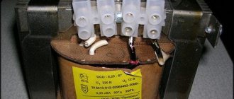
Despite the fact that this device seems at first glance to be a complex device, you can assemble it yourself. The assembly procedure for such a device is very simple. First you need to do some calculations and you can get to work. In order to quickly and easily wind the coils, you need to make a simple device from a board, stands and a handle.
Sample of a homemade device.
First, the characteristics and number of turns on the windings of the device are calculated. In this case, the primary network voltage is 220 V.
It will be interesting➡ What is a traction substation
It is planned to obtain 12 V using the device, with a cross-sectional area of 6 square centimeters, which means a formula is drawn up with the following calculations:
the constant value of the average transformer iron is 60, which should be divided by the area.
The result is 10 - this is the number of turns per volt. The resulting number is multiplied by 220 - this is the number of turns of the primary winding. The number of turns of the second must be calculated according to the same principle: the resulting 10 turns are multiplied by 12 V.
The core can be made from tin cans; to do this, you need to cut strips up to 30 cm long and 2 cm wide. These blanks are fired in an oven over a fire, after which they cool and the scale needs to be cleaned off the surface. Apply varnish and stick strips of paper on one side.
Read material on the topic: How to assemble a step-up transformer with your own hands.
It is also necessary to prepare a paper-insulated wire with a cross-section of 0.3 mm. The secondary winding will be made of wire with a cross section of 1 mm. Use thick cardboard to make the base for the reel. Wrap paraffin paper on it and after that you can start winding the wire.
An example of a connection diagram for a step-down transformer 220 to 12 V.
After every two rows you need to lay a layer of this paper. The secondary winding is wound in the same direction as the first.
Iron strips must be inserted into the finished coil; they should go half their length. These strips cover the base, and the ends are connected at the bottom.
A small distance is left near the core and frame. It is better to make the base for the lowering device from an ordinary board up to 50 mm thick.
It is better to fasten parts using large metal brackets. This must be done so that the brackets go around the bottom of the core. The last step is to bring the ends of the windings onto the frame and secure them with contacts.
To make it easier to wind the coils (factories use special equipment for this), you can use two wooden stands mounted on a board and a metal axle threaded between the holes in the stands. At one end, the metal rod should be bent in the form of a handle.
Design
The design of the device is based on 4 main elements. This is what transformers are made of:
- Magnetic core;
- Windings;
- Connection diagrams for windings of 3-phase transformers;
- Tank.
Magnetic core
The magnetic section of the device is made of several types of materials: electrical steel, permalloy and ferromagnetic materials. The design of the device usually looks like a frame, on the sides (rods) of which windings are placed. The parts of the frame free of coils are called the yoke. Built-in converters are often equipped with toroidal magnetic cores.
Depending on the spatial position of the magnetic cores, magnetic systems can be flat, spatial, symmetrical and asymmetrical structures. In AC transformers, the cores form a closed loop. In DC devices, magnetic cores are made with a gap.
Certain types of magnetic cores
Windings
Magnetic core coils consist of many turns of wire. The turns are arranged parallel to each other in a strictly sequential order. Current conductors, coated with insulating varnish or paper, wrap around the magnetic cores in a spiral.
The energized primary winding creates a magnetic field around itself, which affects the turns of the second coil. As a result, an output electric current is induced in it.
Connection diagrams for windings of 3-phase transformers
In 3-phase transformers, the windings are connected in three ways.
Star
Three windings converge at one end at a neutral point. There are star connections with and without output from a common point.
Triangle
Three windings connected in series form a triangle. For delta-connected windings, the design of the contact switch becomes more complicated due to the high voltage.
Zigzag
With this scheme, all three windings are located separately on 3 magnetic cores. The coils are connected back-to-back in series.
Tank
Tanks filled with transformer oil, in addition to their support function, provide protection against overheating of power equipment. Before filling a sealed tank with oil, the air is pumped out of it. Containers can contain various additives that actively absorb the scattering magnetic flux, preventing it from spreading outward.
How to connect correctly
Connecting a step-down transformer 220-110 or any other configuration is a fairly simple process. Firstly, on factory devices the connection terminals are always marked. To connect the neutral wire, a terminal marked “N” or “0” is used, for the phase wire “L” or “220”. The output is usually “0” and “110”. The last number may vary depending on the output voltage.
Secondly, if you purchased a homemade device or not a new one, where the markings on the terminals have been erased, then you can recognize which winding is primary and which is secondary by the cross-section of the copper wire used in it. So, in the primary winding the wire cross-section is smaller than in the secondary. In a step-up transformer the opposite is true. That is, a thin wire is installed on the secondary winding.
Types of transformers
This paragraph covers the topic of what different transformers there are.
Power
This type of AC power transformer is used in power supply networks and in special installations. The name “Power” means that the equipment has great power. The need for such equipment is explained by the coordination of different voltage values of power lines.
Autotransformer
Its primary and secondary windings are directly connected, thereby providing electromagnetic and electrical communication. The advantage of an autotransformer is its high efficiency. The secondary winding has several terminals, which allows you to vary the output voltage by several values. The device can record voltage at 220 volts. Therefore, the devices are popular in everyday life, protecting lighting lamps and household electrical and electronic equipment from power surges.
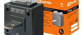
Current transformer
This type, such as a current transformer, is used in measuring circuits and protective equipment. The device is used as a means of control and various signaling. The primary coil is connected to the power source when the secondary winding is included in the circuit of measuring, actuating, indicating and relay devices.
Voltage transformer
The main purpose is to convert high voltage current into low voltage power supply for measuring circuits and various instruments. Step-down equipment is used in logical protection systems.
Pulse
Pulse converters are used to transmit pulsating current. This is a necessary part of video technology to ensure the absence of distortion in the converted video signals.
Welding
Transformers provide the current of the required characteristics for various types of welding. The welding current is adjusted by changing the inductive reactance and the open circuit of the secondary winding. The welding transformer operates from a mains voltage of 220 or 380 volts.
Dividing
Transformers are equipped with separate windings. They are used in circuits of protective systems. They are sensitive to unauthorized grounding and turn off electricity in emergency situations.
Coordinator
A transformer is used to match the resistances of stages of electronic equipment with minimal signal distortion. It is also used for galvanic isolation between different parts of electronic circuits.
Peak transformer
Converts sinusoidal voltage into peak-shaped pulses. Used to control gas-discharge equipment such as thyratrons, mercury rectifiers and thyristors.
Twin throttle
It differs from other types of voltage converters by the presence of two absolutely identical windings. The main function is a counter inductive filter. Its characteristics are significantly superior to the standard design choke.
Transfluxor
It has a high degree of residual magnetization of the core. This type of transformer is used as an element of the memory block of electronic devices.
Rotary transformer
Transmits signals to rotating magnetic heads of video recording equipment. The magnetic core is divided into two parts, one of which rotates with minimal clearance relative to the other part of the core. Provides high-quality signal acquisition at high rotation speeds.
Air and oil transformers
They differ from each other in the way they cool the magnetic core with windings. The oil-based voltage converter is immersed in a sealed tank filled with transformer oil with active additives. Air devices are cooled due to natural or forced ventilation of the internal space of the transformer housing.
Three-phase
This type of equipment refers to power transformers with high power. The magnetic core consists of three rods with windings. The rod of each of the three phases is equipped with two increasing and decreasing voltage coils.
Why do you need a step-down transformer?
The variety of designs available on the market allows you to choose the optimal model for a specific application:
- The energy industry uses high-power step-down devices - up to 1000 MVA. Manufactured models: 765/220 kV, 410/220 kV, 220/110 kV.
- To adapt high voltage to the parameters of a household electrical network, small distribution transformers are used, the power of which reaches 1-5 MVA. On the high voltage side, values of 10, 20, 35 kV can be provided, on the low side - 400 or 230 V.
- For household appliances, transformers are usually used that change the voltage from 220-230 V to 42, 36, 12 V. The specific value of Uout is determined by the requirements of the consumer.
When selecting optimal devices, the total power of consumers, the voltage at the input and output, the need (or lack thereof) for frequency changes, dimensions and weight are taken into account.
Exploitation
Life time
With proper and timely maintenance, transformer equipment can last until it becomes obsolete. The service life depends on operating conditions and the frequency of emergency situations in the section of the electrical network where the equipment is installed.
Parallel operation
Parallel operating mode allows you to temporarily replace high-power power equipment with medium or low power transformers. This occurs when the load on the power line drops, which allows you to reduce energy waste when idling.
Frequency
At the same voltage, the current frequency can be different. The primary winding, designed for a current frequency of 50 Hz, accepts an input current of 60 Hz without interference. Otherwise, the transformer will not fully perform its functions. At a lower rated frequency, the induction rate in the core increases, which, as a rule, causes a sharp increase in the no-load current. If the current in the network has a frequency exceeding the rated value, then parasitic currents arise in the magnetic circuit. The core and windings overheat greatly.
Transformer voltage regulation
Changes in network voltage are displayed on an analog screen or digital display. Low-power transformers are equipped with LED voltage level indication. Using the controls, the desired output voltage level is set in manual or automatic mode.
Transformer insulation
Due to frequent overheating of windings and magnetic circuits, the insulation may lose its dielectric properties. To monitor the insulation condition, regular tests of electrical equipment are carried out.
Transformer overvoltage
During intensive use, transformers are often subject to overvoltage. It can be short-term and transitional.
Short-term exceeding of equipment operating parameters occurs within 1 second to several hours. Transient overvoltage can accumulate over time, measured in miles and nanoseconds.
Before leaving the manufacturing plant, transformers undergo testing, during which various situations are created on the verge of loss of performance. As a result, substandard products are eliminated from the batch of finished products.
When installing any transformer equipment, you need to carefully weigh its capabilities and the condition of the power source. The required output voltage characteristics for certain consumers are also taken into account.
What is the difference between a current transformer and a voltage transformer?
The main difference between current transformers (CTs) and voltage converters is their different functional purposes.
The former are used only in measuring circuits, allowing the level of the controlled parameter to be reduced to an acceptable value. The latter are installed in AC electrical lines and output voltages used to operate connected household equipment. Their design differences are as follows:
- the power supply bus on which it is mounted is used as the primary winding in current transformers;
- the parameters of the secondary winding are designed for connection to a measuring device (an electric meter in a house, for example);
- In comparison with the VT, the current transformer is more compact and has a simplified connection circuit.
Current and voltage transformers meet various requirements regarding the accuracy of the converted quantities. If this indicator is very important for a measuring device, then for a voltage transformer it is of secondary importance.