Calculation of reactive power of a synchronous motor
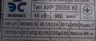
In this example, it is necessary to determine the reactive power generated by a synchronous motor of the STM-800-2 series with a voltage of 6 kV and a power of 800 kW.
Technical characteristics for the engine are accepted according to [L1, p. 204] or according to the manufacturer’s catalog:
- Rated active power on the motor shaft – Рн = 800 kW;
- Efficiency factor (efficiency) – ηн = 0.941;
- Power factor – cosφн=0.9;
1. Determine the reactive power factor of a synchronous motor, knowing the value of cosϕн=0.9:
2. We determine the reactive power of a synchronous motor using expression 35 [L2, p.55]:
3. For rough calculations, the rated reactive power of a synchronous motor can be determined by expression 36 [L2, p.55]:
Qн = 0.5*Рн = 0.5*800 = 400 kvar
As can be seen from the calculation results, the values are not very different.
I would also like to add that when generating reactive power by synchronous motors, active losses arise.
4. For rough calculations, active power losses during reactive power generation can be approximately calculated based on efficiency. engine according to expression 39 [L2, p.56]:
- Operating modes, relay protection and automation of synchronous electric motors. M.I.Slodarzh, 1977
- Reactive power (2nd edition) Minin G.P. 1978
Share on social networks
If you have found the answer to your question and you want to thank the author of the article for his work, you can use the platform for transferring funds “WebMoney Funding”.
This project is supported and developed exclusively with funds from voluntary donations.
By showing loyalty to the site, you can transfer any amount of money, thereby you will help improve this site, increase the regularity of new interesting articles and pay for regular expenses, such as: payment for hosting, domain name, SSL certificate, salary to our authors.
This article will discuss the principle of operation and what components the RCD consists of. Device.
Let's consider an example of choosing a switch in a 6(10) kV network. In our case, we need to choose SF6.
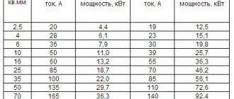
It is necessary to determine the cable cross-sections in a 0.4 kV network to power an AIR200M2 electric motor with a power of 37.
To correctly select current transformers (CTs) for metering meters, we need to choose the right ones.
This article will discuss the calculation of such technical characteristics of an asynchronous electric motor.
By sending a message, you consent to the collection and processing of personal data. Privacy Policy.
Source
Synchronous compensator
A simplified design for idle speed is called a compensator.
Electricity consumption, in addition to active power, requires reactive power. The generator produces reactive power at minimal cost. The reactive power transfer of the generator is associated with losses on the transmission line. Therefore, the use of compensators is economically justified. When excited, synchronous motors do not use mains voltage, but when overexcited, they release reactive power.
The synchronous electric motor is used in AC and DC networks, ensuring high operational reliability. This motor will improve the plant's power factor.
Determination of electric motor power by current consumption
The power of a motor can be determined by the current it consumes. To measure the current we will use a current clamp.
Before starting measurements, first turn off the voltage supply to the electric motor. After this, remove the cover from the terminal box and straighten the conductive wires to ensure easy access to them.
Then we apply voltage to the engine and let it run at rated load for several minutes. We set the measurement limit to the value “200 A” and use a current clamp to measure the current consumed in one of the phases. Next, we measure the voltage on the windings using the probes included in the set of current clamps.
We set the wheel for selecting modes and measurement limits to the position for measuring alternating voltage with a limit of 750 V. We attach the red probe to the socket for measuring voltage, resistance and current up to ten Amperes, and the black one to the “ COM”
.
We take measurements between terminals “U1-V1”
or
“V1-W1”
or
“U1-W1”
.
We calculate the power of the electric motor using the formula:
where S
– total power (kVA), I – current (A),
U
– line voltage value (kV).
We measure the current in one of the phases, as well as the voltage, and substitute the obtained values into the formula (for example, when measuring, we received a current equal to 15.2A and a voltage of 220V):
It is important to note that the electric power. motor does not depend on the connection diagram of the stator windings. This can be verified by taking measurements on the same motor, but with stator windings connected in a star configuration: the measured current will be 8.8A, voltage 380V. We also substitute the values into the formula:
Using this formula, we determined the electric motor power consumed from the electrical network.
To find out the engine power on the shaft, you need to multiply the resulting value by the engine power factor and its efficiency. Thus, the engine power formula looks like this:
where P
– motor shaft power;
S
– total engine power;
сosφ – power factor of an asynchronous electric motor; η
– engine efficiency.
Since we do not have exact data, we will substitute the average values of cosφ and engine efficiency into the formula:
Thus, we determined the power of the electric motor, which is equal to 4 kW.
We talked about the most reliable methods for determining the power of an electric motor. You can also watch our video, which shows in detail how to determine the power of an electric motor.
The original article is posted on our website
If this material was useful to you, please like it
and
share
the article on social networks!
And in order not to miss the release of new articles, subscribe
to our channel: Kabel.RF: everything about electrics.
Source
Advantages and disadvantages of synchronous motors
Starting a synchronous motor
A synchronous motor does not have an initial starting torque. If it is connected to an alternating current network when the rotor is stationary and direct current passes through the excitation winding, then during one period of current change the electromagnetic torque will change its direction twice, i.e. the average moment over the period is zero. Under these conditions, the engine will not be able to start rotating, since its rotor, which has a certain inertia, cannot be accelerated to a synchronous rotation speed within one half-cycle.
Consequently, to start a synchronous motor it is necessary to accelerate its rotor using an external torque to a rotation speed close to synchronous.
Currently, the following starting methods are most often used:
With this method, a synchronous motor is started as an asynchronous one, for which it is equipped with a special short-circuited starting winding made of the “squirrel cage” type. To increase the resistance of the rods, the cage is made of brass. After the rotor accelerates to a rotation speed close to synchronous, voltage is applied to the excitation winding and a direct current passing through it creates a synchronizing torque, which pulls the rotor into synchronism.
2. Start with an auxiliary motor.
The rotor of the excited motor is driven to synchronous speed and connected to the network using a synchronizing device. After this, the auxiliary engine is switched off.
An asynchronous motor with two fewer poles than a synchronous one is usually used as a starting motor.
The disadvantage of this method is the impossibility of starting the engine under load, since it is irrational to have a high-power starting motor.
When starting a synchronous motor at frequency, the frequency of the supply voltage smoothly changes from zero to the nominal one. In this case, the rotor rotates synchronously with the magnetic field of the stator.
The disadvantages of frequency starting are the high cost of the frequency converter, as well as the need to implement complex laws for regulating the initial voltage and frequency during engine acceleration. Frequency starting of synchronous motors is used in drives of special installations.
Synchronous motors have the following advantages:
1. Ability to work at cos φ=
1;
this leads to an improvement in the cos φ
of the network, as well as to a reduction in the size of the motor, since its current is less than the current of an asynchronous motor of the same power. When operating with leading current, synchronous motors serve as generators of reactive power supplied to asynchronous motors, which reduces the consumption of this power from power plant generators.
2. Less sensitivity to voltage fluctuations, since their maximum torque is proportional to the voltage to the first power, and not the square of the voltage.
3. Strict constancy of rotation speed, regardless of the mechanical load on the shaft.
Disadvantages of synchronous motors:
1. Complexity of the design.
2. Comparative difficulty of starting up.
3. Difficulties with regulating the rotation speed, which is only possible by changing the frequency of the supply voltage.
The indicated disadvantages of synchronous motors make them less profitable than asynchronous motors with limited powers of up to 100 kW.
However, at higher powers, when it is especially important to have a high cos φ
and reduced overall dimensions of the machine, synchronous motors are preferable to asynchronous ones.
Your opinion is important to us! Was the published material useful? Yes | No
Source
Electric motor power: formula, calculation rules, types and classification of electric motors
In electromechanics, there are many drives that operate with constant loads without changing the rotation speed. They are used in industrial and household equipment such as fans, compressors and others. If the nominal characteristics are unknown, then the electric motor power formula is used for calculations. Parameter calculations are especially relevant for new and little-known drives. Calculation is performed using special coefficients, as well as based on accumulated experience in working with similar mechanisms. The data is necessary for the correct operation of electrical installations.
What is an electric motor?
An electric motor is a device that converts electrical energy into mechanical energy. The operation of most units depends on the interaction of the magnetic field with the rotor winding, which is expressed in its rotation. They operate from DC or AC power sources. The power supply can be a battery, an inverter or a power outlet. In some cases, the engine works in reverse, that is, it converts mechanical energy into electrical energy. Such installations are widely used in power plants powered by air or water flow.
Electric motors are classified by type of power source, internal design, application and power. Also, AC drives may have special brushes. They operate on single-phase, two-phase or three-phase voltage and are air or liquid cooled. AC motor power formula
where P is power, U is voltage, I is current.
General purpose drives with their own sizes and characteristics are used in industry. The largest engines with a power of more than 100 Megawatts are used in the power plants of ships, compressor and pumping stations. Smaller sizes are used in household appliances, such as a vacuum cleaner or fan.
Operating principle of synchronous machines
The operating principle of a synchronous machine is based on the interaction of two types of magnetic fields. One of these fields is formed by the armature, while the other arises around an electromagnet excited by direct current - an inductor. Immediately after reaching operating power, the magnetic field created by the stator and rotating inside the air gap meshes with the magnetic fields at the poles of the inductor. Thus, in order for a synchronous machine to reach its operating speed, a certain amount of time is required to accelerate it. After the machine accelerates to the required frequency, power is supplied to the inductor from a DC source.
Electric motor design
Drive includes:
The rotor is the only moving part of the drive that rotates around its axis. The current passing through the conductors forms an inductive disturbance in the winding. The generated magnetic field interacts with the permanent magnets of the stator, which causes the shaft to move. They are calculated using the formula for electric motor power by current, for which the efficiency and power factor are taken, including all the dynamic characteristics of the shaft.
Bearings are located on the rotor shaft and contribute to its rotation around its axis. The outer part is attached to the engine housing. The shaft passes through them and comes out. Since the load extends beyond the working area of the bearings, it is called overhanging.
The stator is a stationary element of the electromagnetic circuit of the engine. May include winding or permanent magnets. The stator core is made of thin metal plates called the armature package. It is designed to reduce energy loss, which often occurs with solid rods.
Air gap is the distance between the rotor and stator. A short gap is effective, as it affects the low efficiency of the electric motor. The magnetizing current increases with increasing gap size. Therefore, they always try to make it minimal, but to reasonable limits. Too small a distance leads to friction and weakening of the fixing elements.
The winding consists of copper wire assembled into one coil. Typically laid around a soft magnetized core consisting of several layers of metal. The induction field is disturbed when current passes through the wires of the winding. At this point, the installation enters configuration mode with explicit and implicit poles. In the first case, the magnetic field of the installation is created by a winding around the pole piece. In the second case, the slots of the rotor pole piece are dispersed in the distributed field. A shaded pole motor has a winding that inhibits magnetic disturbance.
The switch is used to switch the input voltage. It consists of slip rings located on the shaft and isolated from each other. The armature current is supplied to the contact brushes of the rotary commutator, which causes a change in polarity and causes the rotor to rotate from pole to pole. If there is no voltage, the motor stops turning. Modern installations are equipped with additional electronic means that control the rotation process.
Structure of an asynchronous single-phase motor
Single Phase AC Brushed Motor
So, in the first part of the article, we discussed the general concepts about single-phase motors, the principle of their operation and connection. Such information would be enough for a superficial study, but we are not entirely satisfied with this approach. For lovers of technical details, let's now look at everything in more detail.
Asynchronous motor
Electric motors are either synchronous or asynchronous. The difference between them is that in synchronous, the speed of rotation of the armature coincides with the rotation of the magnetic field, while in asynchronous the rotor lags somewhat behind.
- The last option is the most common, as it has a simpler design and is very reliable. Synchronous ones are used only in those areas where control of engine speed is very important.
- You have probably already noticed that the word phase refers to different concepts - the number of supply wires, the windings on the stator, and the angular shift. And we even said that single-phase motors actually have two phases, but they are called such precisely by the number of supply wires.
- We also wrote that the motor has moving and fixed parts. Let's look at their structure in more detail.
Single-phase AC commutator motors
- The rotor of the unit is a shaft that is supported in the engine housing using rotation bearings. Due to them, it rotates freely around its axis. The structure of this element will differ depending on whether the engine is brushed or brushless. Let's start with the second one.
- A magnetic circuit is fixed to the shaft of the brushless phase rotor, which is assembled from laminated steel plates.
- On the outside of the magnetic circuit there are grooves in which the winding rods are located - usually made of copper.
Motor with phase-type rotor
- At the ends, the rods are connected to rings that short-circuit them - they are called closing rings.
Structure of a wound rotor
- A current will flow inside this winding, which is induced by the magnetic field of the stator - it has no external connections.
- The magnetic core serves for better passage of the magnetic field that is created in the rotor.
- Such devices are characterized by high reliability, since they do not have rubbing parts. The motor rotation speed is controlled only by the current on the main stator winding.
- A single-phase AC commutator motor is not much different in structure from the rotor of a DC motor. Actually, such motors are universal and can be powered by both alternating and direct current.
- The rotor phases are connected to the power supply through a commutator, which is in contact with the brushes, which in turn are already connected to the supply circuit.
- The structure of such engines is more complex, and their reliability will also be lower, but they are more flexible in control.
In the photo - the stator of the electric motor
- The stator is the passive part of the electric motor - it is motionless and consists of a magnetic core and winding.
- The purpose of this element is to generate a stationary or rotating magnetic field.
- A single-phase motor will have four terminals coming from the stator - two for the working winding and two for the starting winding. We have already written how to distinguish them.
In addition to these elements, the engines have the following components:
- The frame and body of the device , which hold all the working parts and allow you to fix the device on the surface;
- External electrical circuit - power button, speed control device, wires and devices for bypassing the additional winding;
- Impeller – active cooling of the engine, also located on the shaft;
- Rotation bearings.
Operating principle
According to Archimedes' law, the current in a conductor creates a magnetic field in which the force F1 acts. If a metal frame is made from this conductor and placed in a field at an angle of 90°, then the edges will experience forces directed in the opposite direction relative to each other. They create a torque about the axis, which begins to rotate it. The armature coils provide constant torsion. The field is created by electric or permanent magnets. The first option is made in the form of a coil winding on a steel core. Thus, the frame current generates an induction field in the electromagnet winding, which generates an electromotive force.
Let us consider in more detail the operation of asynchronous motors using the example of installations with a wound rotor. Such machines operate on alternating current with an armature rotation frequency that is not equal to the pulsation of the magnetic field. That's why they are also called induction. The rotor is driven by the interaction of electric current in coils with a magnetic field.
When there is no voltage in the auxiliary winding, the device is at rest. As soon as an electric current appears at the stator contacts, a constant magnetic field with pulsation +F and -F is formed. It can be represented as the following formula:
npr is the number of revolutions that the magnetic field makes in the forward direction, rpm;
nrev — number of field revolutions in the opposite direction, rpm;
f1—electric current pulsation frequency, Hz;
p—number of poles;
n1 is the total number of revolutions per minute.
Experiencing pulsations of the magnetic field, the rotor receives initial movement. Due to the heterogeneity of the impact of the flow, it will develop a torque. According to the law of induction, an electromotive force is generated in a short-circuited winding, which generates a current. Its frequency is proportional to the rotor slip. Due to the interaction of electric current with a magnetic field, shaft torque is created.
Principle of operation
The constant speed of rotation of a synchronous electric motor is achieved through the interaction between a constant and rotating magnetic field. The rotor of a synchronous electric motor creates a constant magnetic field, and the stator creates a rotating magnetic field.
The operation of a synchronous electric motor is based on the interaction of the rotating magnetic field of the stator and the constant magnetic field of the rotor
Stator: rotating magnetic field
Three-phase alternating voltage is supplied to the windings of the stator coils. As a result, a rotating magnetic field is created, which rotates at a speed proportional to the frequency of the supply voltage. More information about how a rotating magnetic field is formed using a three-phase supply voltage can be found in the article “Three-phase asynchronous electric motor”.
Types of electric motors
Based on the power source, drives are divided into those powered by:
- Direct current.
- Alternating current.
According to the principle of operation, they, in turn, are divided into:
Valve motors are not classified as a separate class, since their design is a variation of a commutator drive. Their design includes an electronic converter and a rotor position sensor. They are usually integrated together with a control board. Due to them, coordinated commutation of the armature occurs.
Synchronous and asynchronous motors operate exclusively on alternating current. The speed is controlled using sophisticated electronics. Asynchronous are divided into:
Theoretical formula for the power of a three-phase electric motor when connected in a star or delta
However, for linear values of voltage and current it looks like
This will be a real indicator of how much power the engine takes from the network.
Synchronous are divided into:
- Stepper.
- Hybrid.
- Inductor.
- Hysteretic.
- Reactive.
Stepper motors have permanent magnets in their design, so they are not classified as a separate category. The operation of the mechanisms is controlled using frequency converters. There are also universal motors that operate on direct and alternating current.
Starting a synchronous motor
One of the main disadvantages of synchronous motors is the difficulty of starting them. Synchronous motors can be started using an auxiliary starting motor or by asynchronous starting.
Starting a synchronous motor using an auxiliary motor. If the rotor of a synchronous motor with excited poles is rotated by another, auxiliary motor to the speed of rotation of the stator field, then the magnetic poles of the stator, interacting with the poles of the rotor, will force the rotor to rotate further independently without outside help, in time with the stator field, i.e. synchronously (from where These engines got their name).
D
To start, it is necessary that the number of pole pairs of the asynchronous motor be less than the number of pole pairs of the synchronous motor, because under these conditions the auxiliary asynchronous motor can rotate the rotor of the synchronous motor to synchronous speed.
The procedure for starting a synchronous motor is as follows. By turning on the switch 3, the auxiliary asynchronous motor 2 is started, which turns the rotor of the synchronous motor 1 to a speed corresponding to the speed of the stator field. The rotation speed of the auxiliary engine is determined by the tachometer1. Then, turning on the DC switch 4, the rotor poles are excited. To turn on a synchronous motor in a three-phase current network, it must be synchronized in the same way as when turning on a synchronous generator for parallel operation. To do this, rheostat 5 sets the excitation such that the voltage of the stator winding according to the voltmeter V is equal to the network voltage indicated by the voltmeter V1.
The difficulty of starting and the need for an auxiliary motor are significant disadvantages of this method of starting synchronous motors. Therefore, it is rarely used nowadays.
Asynchronous starting of a synchronous motor. To implement this starting method, an additional short-circuited winding is placed in the pole pieces of the rotor poles. Since during start-up a large e is induced in the excitation winding 1 of the motor. d.s, then for safety reasons it is closed by switch 2 to resistance 3
P
When the voltage of a three-phase network is turned on in the stator winding 4 of a synchronous motor, a rotating magnetic field appears, which, crossing the short-circuited (starting) winding embedded in the pole pieces of the rotor, induces currents in it.
These currents, interacting with the rotating field of the stator, will cause the rotor to rotate. When the rotor reaches its maximum speed (95-97% of the synchronous speed), switch 2 is switched so that the rotor winding is connected to a DC voltage network.
The disadvantage of asynchronous starting is the large starting current (5-7 times greater than the operating current). The inrush current causes a voltage drop in the network, and this affects the operation of other consumers. To reduce the starting current, starting at a reduced voltage is used using reactor 2 or an autotransformer.
Currently, asynchronous starting of synchronous motors is used almost exclusively due to its simplicity and reliability. There are also schemes for automatic asynchronous starting of synchronous motors
Source
General characteristics of engines
All motors have common parameters that are used in the formula for determining the power of an electric motor. Based on them, the properties of the machine can be calculated. In different literature they may be called differently, but they mean the same thing. The list of such parameters includes:
- Torque.
- Engine power.
- Efficiency.
- Nominal speed.
- Rotor moment of inertia.
- Design voltage.
- Electrical time constant.
The above parameters are necessary, first of all, to determine the efficiency of electrical installations operating due to the mechanical force of motors. Calculated values give only an approximate idea of the actual characteristics of the product. However, these indicators often use electric motor power in the formula. It is this that determines the performance of the machines.
Torque
This term has several synonyms: torque, motor torque, torque, torque. All of them are used to denote one indicator, although from the point of view of physics these concepts are not always identical.
In order to unify terminology, standards have been developed that bring everything to a single system. Therefore, in technical documentation the phrase “torque” is always used. It is a vector physical quantity that is equal to the product of the vector values of force and radius. The radius vector is drawn from the axis of rotation to the point of applied force. From a physics perspective, the difference between torque and torque lies in the point at which the force is applied. In the first case it is an internal effort, in the second it is an external one. The value is measured in newton meters. However, in the electric motor power formula, torque is used as the main value.
It is calculated as
M — torque, Nm;
F is the applied force, H;
To calculate the rated torque of the drive, use the formula
Rnom - rated power of the electric motor, W;
nnom - nominal speed, min -1.
Accordingly, the formula for the rated power of the electric motor should look like this:
Usually all characteristics are indicated in the specification. But it happens that you have to work with completely new installations, information about which is very difficult to find. To calculate the technical parameters of such devices, data from their analogs is taken. Also, only the nominal characteristics that are given in the specification are always known. Real data must be calculated independently.
Engine power
In a general sense, this parameter is a scalar physical quantity, which is expressed in the rate of consumption or conversion of energy of the system. It shows how much work the mechanism will perform in a certain unit of time. In electrical engineering, the characteristic displays the useful mechanical power on the central shaft. To designate the indicator, use the letter P or W. The main unit of measurement is Watt. The general formula for calculating the power of an electric motor can be presented as:
A—mechanical (useful) work (energy), J;
t — time spent, sec.
Mechanical work is also a scalar physical quantity, expressed by the action of a force on an object, and depending on the direction and movement of this object. It is the product of the force vector and the path:
s — distance traveled, m.
It expresses the distance that a point of applied force will travel. For rotational movements it is expressed as:
ds = r × d(teta), where:
theta — rotation angle, rad.
In this way, you can calculate the angular frequency of the rotor:
omega = d(teta) ÷ dt.
From this follows the formula for the power of the electric motor on the shaft: P = M × omega.
ANGULAR AND MECHANICAL CHARACTERISTICS OF A SYNCHRONOUS MOTOR
For a synchronous motor, it is possible to write power expressions of the same type as for a synchronous generator. However, in relation to the engine they will have different meanings.
For engine P
φ = 3
UI
cos φ represents the power it absorbs from the three-phase network. Subtracting from this power the power losses in the armature winding, we obtain electromagnetic power, i.e., power converted from electrical to mechanical, developed by the rotating rotor:
P
em =
P
ψ - Δ
P
i = 3
UI
cos φ -
3I
2
r =
3
E
0
I
cos ψ.
The electromagnetic torque of a synchronous motor can be expressed in terms of power P
em and angular velocity ω = π
n
/30 of the rotor:
M
=
Р
em/ω.
Replacing power P
um by its expression, we get
| M = | 3 E 0 I cos φ | . |
| ω |
(11,13)
If from point A of the vector diagram (Fig. 11.9, a) we lower the perpendicular AG to line OB, then we can obtain the following equality:
I
cos ψ =
U
sin θ/
x
c .
Replacing I
cos ψ in (11.13) by its expression, we obtain
| M = | 3 E 0 U | sin θ. |
| ω x s |
(11,14)
As can be seen, at constant values of U, E,
ω and
x
from the motor torque are directly proportional to sin θ.
The dependence M
(θ) is called the angular characteristic of a synchronous motor and is shown in Fig. 11.10 in the first quadrant.
In the range from θ = 0 to θ = 90° there is a stable part of the characteristic, so called because it is here that stable operation of the engine with different moments of resistance is possible. Any change in the moment of resistance M
s when working on a stable part of the characteristic leads to such a change in the engine torque
M,
at which the equality of the moments
M
and
M
s inevitably occurs.
On the stable part of the characteristic there is point A,
corresponding to the nominal operating mode. At nominal mode θnom = 20 ÷ 30°.
The maximum torque that the engine is able to develop occurs at θ = 90°:
| Mmax = | 3UE 0 | . |
| ω x s |
If the moment of resistance M
c turns out to be greater than the torque
Mmax,
then the engine will not be able to balance it and will stop.
Mmax ratio
/
M
nom is called the overload capacity of the engine and for various engines lies in the range of 2 - 3.2.
The overload capacity can be increased, if necessary, by increasing the EMF E
0. From the expression for the maximum torque it follows that the latter and, therefore, the overload capacity of a synchronous motor is proportional to the first degree of voltage, in contrast to an asynchronous motor, for which it is proportional to the square of the voltage. It follows from this that synchronous motors are less sensitive to voltage changes than asynchronous motors.
It should be noted that long-term load of engines exceeding the rated load is unacceptable, since the engine will overheat. Possible short-term overload must be taken into account when choosing a motor based on power.
Rice. 11.10. Angular characteristic of a synchronous motor
Rice. 11.11. Mechanical characteristics of a synchronous motor
Let's consider the phenomena that occur when the engine load changes. Let us assume that the engine operates with torque M = Mc and angle θ (see Fig. 11.10), which corresponds to the vector diagram shown in Fig. 11.9, a. As a result of a change in the moment of resistance, for example, from Ms to Ms > Ms, a short-term decrease in the rotor speed occurs, which is accompanied by a corresponding change in the frequency of the induced EMF E0 and, consequently, the rotation frequency of the EMF vector E0 in the vector diagram. As a result of this, the phase shift angle θ of the EMF E0 relative to the voltage U returns and, as a result, the current I, voltage drop Ixc, moment of power Pφ and Rem increase.
The listed values increase until at a certain angle θ1 (see Fig. 11.9, b and 11.10) the motor torque M1 is equal to the moment of resistance Мс1. When M1 = Mc1, the rotor rotation frequency will again become equal to the armature field rotation frequency:
n= n0 = 60f/r.
As the moment of resistance decreases, the angle θ and, consequently, the values of I, Ixc, M, Pφ and Rem also decrease, and at θ = 0 all of them, except I and Ixc, turn out to be zero. The vector diagram for the case θ = 0 is given in Fig. 11.9, vAs can be seen, at θ = 0 the motor consumes purely inductive current. It is not difficult to establish that if the motor were excited to the emf E0 = U, then at θ = 0 the current I would be equal to zero.
Since when the motor load changes, only a relatively small displacement of the rotor relative to the rotating field occurs (change in angle θ), the mechanical characteristic of a synchronous motor is represented by a line parallel to the abscissa axis (Fig. 11.11). The engine has a constant speed when the torque changes up to the maximum value.
In addition to the motor mode, synchronous motors can operate in a braking generator mode with energy output to the network. Generator mode occurs when a torque rather than a braking torque is applied to the motor shaft. A motor in regenerative mode is essentially a generator running in parallel with the mains. The angular and mechanical characteristics of the engine in generator mode are shown in Fig. 1, respectively. 11.10 and 11.11 in the third and second quadrants.
Electric motor efficiency
Efficiency is a characteristic that reflects the efficiency of the system in converting energy into mechanical energy. Expressed as the ratio of useful energy to spent energy. According to the unified system of units of measurement, it is designated as “eta” and is a dimensionless value, calculated as a percentage. Formula for electric motor efficiency through power:
P1—electrical (supplied) power, W;
P2 — useful (mechanical) power, W;
It can also be expressed as:
eta = A ÷ Q × 100%, where:
A - useful work, J;
Q is the energy expended, J.
Nominal speed
Another key indicator of the electromechanical characteristics of the engine is the shaft speed. It is expressed in revolutions per minute. It is often used in the pump motor power formula to find out its performance. But it must be remembered that the indicator is always different for idling and operation under load. The indicator represents a physical quantity equal to the number of full revolutions over a certain period of time.
Calculation formula for speed:
n = 30 × omega ÷ pi, where:
n — engine speed, rpm.
In order to find the power of an electric motor using the shaft speed formula, it is necessary to reduce it to the calculation of angular velocity. Therefore P = M × omega will look like this:
P = M × (2pi × n ÷ 60) = M × (n ÷ 9.55), where
Design voltage
It is also called nominal. It is a base voltage represented by a standard set of voltages, which are determined by the degree of insulation of electrical equipment and the network. In reality, it may differ at different points of the equipment, but should not exceed the maximum permissible operating conditions designed for the long-term operation of the mechanisms.
For conventional installations, rated voltage refers to the calculated values for which they are provided by the developer in normal operation. The list of standard network voltage is provided in GOST. These parameters are always described in the technical characteristics of the mechanisms. To calculate performance, use the formula for electric motor power by current:
Electrical time constant
Represents the time required for the current level to reach 63% after voltage is applied to the drive windings. The parameter is determined by transient processes of electromechanical characteristics, since they are fleeting due to high active resistance. General formula for calculating the time constant:
However, the electromechanical time constant tm is always greater than the electromagnetic time constant te. The first parameter is obtained from the equation of the dynamic characteristics of the engine while maintaining the condition when the rotor accelerates from zero speed to maximum idle speed. In this case, the equation takes the form
M = Mst + J × (d(omega) ÷ dt), where
From here we get the formula:
M = J × (d(omega) ÷ dt).
In fact, the electromechanical time constant is calculated from the starting torque - MP. A mechanism operating under ideal conditions with linear characteristics will have the formula:
M = Mп × (1 - omega ÷ omega), where
omega — speed at idle.
Such calculations are used in the formula for the power of a pump electric motor, when the piston stroke directly depends on the speed of the shaft.
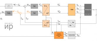
What are thyristor exciters and what are they for?
What are thyristor exciters for synchronous motors, how do they work and where are they used. Types of thyristor exciters and operating modes.
Electronic excitation control devices are widely used in industry. They are necessary to supply voltage to the excitation and control windings. Designed for automatic regulation of excitation currents during direct or reactor starting from a frequency converter or network. Implements stable operation in synchronous and emergency operation modes of powerful synchronous electric motors. The advantages of such systems are ease of control, compactness, integration into electronic control systems in automatic control systems, where remote parameter changes are used. Next, we will talk in detail about what thyristor exciters are, what types they are and how they work.
Basic formulas for calculating engine power
To calculate the actual characteristics of mechanisms, many parameters must always be taken into account. First of all, you need to know what kind of current is supplied to the windings of the electric motor: direct or alternating. The principle of their operation is different, therefore the calculation method is different. If a simplified form of calculating drive power looks like:
U—voltage, V;
Rel - supplied electrical power. Tue
In the AC motor power formula, phase shift (alpha) must also be taken into account. Accordingly, the calculations for an asynchronous drive look like:
Pel = U × I × cos(alpha).
In addition to active (supplied) power, there is also:
- S - reactive, VA. S = P ÷ cos(alpha).
- Q - full, VA. Q = I × U × sin(alpha).
The calculations also need to take into account heat and induction losses, as well as friction. Therefore, a simplified model formula for a DC motor looks like:
Rel = P fur + Rtep + Rind + Rtr, where
Рmekh - useful generated power, W;
Rtep—losses for heat generation, VT;
Rind is the cost of charging in the induction coil, W;
RT - losses due to friction, W.