Classification of vector control methods
Since the seventies of the twentieth century, many methods of torque control have been proposed. Not all of them are widely used in industry. Therefore, this article discusses only the most popular management methods. The torque control methods discussed are presented for control systems for induction motors and permanent magnet synchronous motors with sinusoidal back EMF.
Existing torque control methods can be classified in various ways.
- Most often, torque control methods are divided into the following groups:
- linear (PI, PID) regulators;
- nonlinear (hysteresis) regulators.
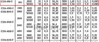
| Control method | Speed control range | Speed error3,% | Torque rise time, ms | Starting torque | Price | Description | ||
| Scalar | 1:101 | 5-10 | Not available | Short | Very low | It has a slow response to load changes and a small speed control range, but is easy to implement. | ||
| Vector | Linear | Field-oriented control | >1:2002 | 0 | High | High | Allows you to smoothly and quickly control the main engine parameters - torque and speed. For this method to work, information about the rotor position is required. | |
| Direct torque control with FDA | >1:2002 | 0 | High | High | A hybrid method designed to combine the advantages of POU and PUM. | |||
| Nonlinear | Direct torque control with switching table | >1:2002 | 0 | High | High | It has high dynamics and a simple circuit, but a characteristic feature of its operation is high current and torque ripples. | ||
| Direct self-government | >1:2002 | 0 | High | High | It has an inverter switching frequency lower than other methods and is designed to reduce losses when controlling high-power electric motors. | |||
Characteristics of the main methods of controlling AC motors [2]
Note:
- No feedback.
- With feedback.
- In steady state
Among vector control, the most widely used are field-oriented control (FOC - field oriented control) and direct torque control (DTC - direct torque control).
Vector feedback control
This mode features higher precision control of engine speed. Feedback is provided by an encoder, which interfaces with the frequency converter through an additional module.
The encoder is installed on the shaft of an electric motor or subsequent mechanism and transmits data about the current rotation speed. Based on the information received, the converter changes the voltage, torque and, accordingly, the speed of the motor. It is worth adding that under high dynamic loads (frequent torque changes) and operation at low speeds, it is recommended to use forced cooling with an external fan.
Source
Linear torque regulators
Linear torque controllers work in conjunction with pulse width modulation (PWM) of the voltage. The regulators determine the required stator voltage vector averaged over the sampling period. The voltage vector is finally synthesized by the PWM method; in most cases, space vector modulation (SVM) is used. Unlike nonlinear torque control circuits, where signals are processed using instantaneous values, in linear torque control circuits, a linear controller (PI) operates with values averaged over the sampling period. Therefore, the sampling frequency can be reduced from 40 kHz in nonlinear torque controller circuits to 2-5 kHz in linear torque controller circuits.
- The group of linear regulators includes the following torque control methods:
- field-oriented control (FOC);
- direct torque control with voltage space vector modulation (DTC-SVM);
- direct torque control with flux vector modulation (DTC-FVM).
Field-oriented control
Field-oriented control
(POA, English field oriented control, FOC) is a control method that controls a brushless alternating current electric motor (BPSM, ADKR) as a DC machine with independent excitation, implying that the field and torque can be controlled separately.
Field-oriented control, proposed in 1970 by Blaschke [3] and Hasse [4], is based on an analogy with a mechanically commutated separately excited DC motor. In this motor, the field and armature windings are separated, the flux linkage is controlled by the field current of the inductor, and the torque is independently controlled by adjusting the armature current. Thus, the flux linkage and torque currents are electrically and magnetically separated.
General functional diagram of sensorless field-oriented control1
Note:
- The diagram is shown in a simplified form. Detailed diagram of sensorless field-oriented control of a PMSM with a rotor with salient poles.
On the other hand, brushless alternating current motors (ABAC, PMSM) most often have a three-phase stator winding, and the stator current vector Is is used to control both flux linkage and torque. Thus the field current and armature current are combined
into the stator current vector and cannot be controlled separately. Disconnection can be achieved mathematically - by decomposing the instantaneous value of the stator current vector Is into two components: the longitudinal component of the stator current Isd (creating the field) and the transverse component of the stator current Isq (creating torque) in a rotating dq coordinate system oriented along the rotor field (R-FOC - rotor flux-oriented control) - picture above. Thus, the control of a brushless AC motor becomes identical to the control of an independently excited DC motor and can be carried out using a PWM inverter with a linear PI regulator and space-vector voltage modulation.
In field-oriented control, torque and field are controlled indirectly by controlling the stator current vector components.
The instantaneous values of the stator currents are converted to the dq rotating coordinate system using the Park transformation αβ/dq, which also requires information about the rotor position. The field is controlled through the longitudinal current component Isd, while the torque is controlled through the transverse current component Isq. The inverse Park transform (dq/αβ), a mathematical coordinate transformation module, allows you to calculate the reference voltage vector components Vsα* and Vsβ*.
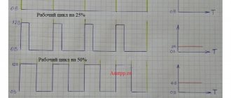
Waveforms at different stages of conversion
To determine the rotor position, either a rotor position sensor installed in the electric motor or a sensorless control algorithm implemented in the control system is used, which calculates information about the rotor position in real time based on the data available in the control system.
Direct torque control with space vector modulation
- Direct torque control with space vector voltage modulation
- Direct torque control with space vector flux modulation
Direct torque control with space vector modulation is carried out in a rectangular coordinate system oriented along the stator field, therefore this control does not require information about the rotor position.
In particular, this method realizes sensorless control of a permanent magnet synchronous motor over the entire speed range, including low speed, without the need to apply a high-frequency signal and change the rotor design, as is done in sensorless field-oriented permanent magnet motor control.
Direct torque control with space vector voltage modulation
A block diagram of direct torque control with space-vector modulation with torque and flux linkage adjustment with feedback operating in a rectangular coordinate system oriented along the stator field is shown in the figure below. The PI outputs of the torque and flux linkage controllers are interpreted as the reference components of the stator voltage Vψ* and VM* in the dq coordinate system oriented along the stator field (English stator flux-oriented control, S-FOC). These commands (DC voltages) are then converted into a fixed coordinate system αβ, after which the control values Vsα* and Vsβ* are sent to the space vector modulation module.
Functional diagram of direct torque control with space vector voltage modulation
Please note that this circuit can be considered as a simplified stator field-oriented control (S-FOC) without a current control loop or as a classic direct torque control circuit with a switching table (PUM-TV, English switching table DTC, ST DTC) in which the switching table was replaced by a modulator (FVM), and the hysteresis torque and flow controller were replaced by linear PI controllers.
In direct torque control with space vector modulation (DTC-FCM), the torque and flux linkage are directly controlled in a closed loop, so accurate estimation of the motor flux and torque is necessary. Unlike the classic hysteretic direct torque control algorithm, PUM-PVM operates at a constant switching frequency. This significantly improves the performance of the control system: it reduces torque and flow pulsations, allowing you to confidently start the engine and operate at low speeds. But at the same time, the dynamic characteristics of the drive are reduced.
Direct torque control with space vector flux modulation
Direct torque control with space vector flux modulation is a simplified version of the direct torque control circuit with space vector voltage modulation. In this case, during control there is no transformation from a fixed coordinate system to a rotating one (αβ -> dq).
Functional diagram of direct torque control with space vector flux modulation
To control the torque of the electric motor, a PI regulator is used to control the increment in the torque angle Δδ for a given change in torque ΔM at the input. The use of a PI controller is due to the fact that the relationship between the change in torque ΔM and the increment in the torque angle Δδ is complex and nonlinear [7]. Then the torque angle increment Δδ is added to the stator flux vector angle θs in the stator field-oriented rectangular coordinate system α, β to calculate the stator flux control vector ψs*. The obtained value of the control vector of the stator flux is compared with the estimated flux, after which the resulting difference Δψs is used by the PVMP block to calculate the control vector of the stator voltage and calculate the switching states of the inverter keys [8]. In this circuit, due to the presence of a stator flux control loop used to calculate Δψs, the use of a PI flux controller is not required.
Building a vector control structure
But how is vector control achieved in practice? Obviously, first you need to know the position of the rotor so that you have something to measure 90° relative to. The easiest way to do this is by installing the position sensor itself on the rotor shaft. Then you need to figure out how to create a current vector, maintaining the desired currents in phases α
and
β
. We apply voltage to the motor, not current... But since we want to support something, we need to measure it. Therefore, for vector control you will need phase current sensors. Next, you need to assemble a vector control structure in the form of a program on a microcontroller that will do the rest. So that this explanation does not look like an instruction on “how to draw an owl,” let’s continue the dive. You can maintain the current with the microcontroller using a software PI (proportional-integral) current regulator and PWM. For example, a structure with a current regulator for one phase α is shown below (Figure 3).
Figure 3. Current-closed control structure for one phase
Here the current setting iα_back
– a certain constant, the current that we want to maintain for this phase, for example 1A.
The task is sent to the current regulator adder, the disclosed structure of which is shown above. If the reader does not know how the PI controller works, then alas. I can only recommend some of this. The output current regulator sets the phase voltage Uα
.
The voltage is supplied to the PWM unit, which calculates the duty cycle settings (comparison settings) for the PWM timers of the microcontroller, which generate PWM on a four-switch bridge inverter to generate this Uα
.
The algorithm can be different, for example, for positive voltage the PWM of the right rack is proportional to the voltage setting, the lower switch is closed on the left, for negative PWM the left one, the lower switch is closed on the right. Don't forget to add dead time! As a result, such a structure makes a software “current source” at the expense of a voltage source: we set the value iα_set
, and this structure implements it with a certain speed.
Further, perhaps some readers have already thought that the vector control structure is only a small matter away - you need to install two current regulators, one regulator for each phase, and form a task on them depending on the angle from the rotor position sensor (RPS), i.e. e. make something like this structure (Figure 4):
Figure 4. Incorrect (naive) vector control structure
You can't do that. When the rotor rotates, the variables iα_rear
and
iβ_back
will be sinusoidal, i.e. the task for the current regulators will change all the time. The speed of the controller is not infinite, so when the task changes, it does not immediately process it. If the task is constantly changed, then the regulator will always catch up with it, never reaching it. And as the engine rotation speed increases, the lag of the real current from the given one will become larger and larger, until the desired angle of 90° between the current and the rotor magnet ceases to be similar to it at all, and the vector control ceases to be so. That's why they do it differently. The correct structure is as follows (Figure 5):
Figure 5. Vector sensor control structure for two-phase synchronous machine
Two blocks have been added here - BKP_1 and BKP_2: blocks of coordinate transformations. They do a very simple thing: they rotate the input vector by a given angle. Moreover, BOD_1 turns to + ϴ
, and BKP_2 on -
ϴ
.
That's all the difference between them. In foreign literature they are called Park transformations. BKP_2 makes a coordinate transformation for currents: from the stationary axes α
and
β
tied to the motor stator, to the rotating axes
d
and
q
tied to the motor rotor (using the rotor position angle
ϴ
).
And BKP_1 makes the reverse transformation, from setting the voltage along the d
and
q
, it makes the transition to the
α
and
β
. I don’t provide any formulas for converting coordinates, but they are simple and very easy to find. Actually, there is nothing more complicated than school geometry (Figure 6):
Figure 6. Coordinate transformations from fixed axes α and β, tied to the motor stator, to rotating axes d
and
q
tied to the rotor
That is, instead of “rotating” the settings of the regulators (as was the case in the previous structure), their inputs and outputs rotate, and the regulators themselves operate in static mode: currents d
,
q
and controller outputs in steady state are constant.
d
and
q
axes rotate together with the rotor (as they are rotated by a signal from the rotor position sensor), while the
q
regulates exactly the current that at the beginning of the article I called “perpendicular to the rotor field”, that is, it is a torque-forming current, and the current
d
is co-directed with the “rotor magnet”, so we don’t need it and we set it equal to zero. This structure is free from the disadvantage of the first structure - the current regulators do not even know that something is spinning somewhere. They work in a static mode: they have adjusted each of their currents, reached the specified voltage - and that’s it, like the rotor, don’t run away from them, they won’t even know about it: all the work of turning is done by coordinate transformation blocks.
To explain “on the fingers” you can give some analogy.
For linear traffic, let it be, for example, a city bus. It constantly accelerates, then slows down, then goes backwards and generally behaves as it wants: it is an engine rotor. Also, you are in a car nearby, driving in parallel: your task is to be exactly in the middle of the bus: “keep 90°”, you are the current regulators. If the bus changes speed all the time, you should also change the speed accordingly and monitor it all the time. But now we’ll do “vector control” for you. You climbed inside the bus, stood in the middle and held on to the handrail - like the bus, don’t run away, you can easily cope with the task of “being in the middle of the bus.” Similarly, current regulators, “rolling” in the rotating axes d, q of the rotor, live an easy life.
The above structure actually works and is used in modern electric drives. Only it lacks a whole bunch of small “improvements”, without which it is no longer customary to make it, such as compensation for cross-connections, various restrictions, field weakening, etc. But this is the basic principle.
And if you need to regulate not the drive torque, but still the speed (the correct angular speed, rotation frequency)? Well then we install another PI controller - a speed controller (RS). We apply a speed command to the input, and at the output we have a torque command. Since the q
is proportional to the torque, then, to simplify things, you can apply the output of the speed controller directly to the input of the
q-
, like this (Figure 7):
Figure 7. Speed controller for vector control Here the ZI, an intensity setter, smoothly changes its output so that the engine accelerates at the desired pace, and does not drive at full current until the speed is set. Current rotation speed ω
taken from the rotor position sensor handler, since
ω
is the derivative of the angular position
ϴ
. Well, or you can simply measure the time between sensor pulses...
How to do the same for a three-phase motor? Well, actually, nothing special, we add another block and change the PWM module (Figure 8).
Figure 8. Vector sensor control structure for three-phase synchronous machine
Three-phase currents, just like two-phase ones, serve one purpose - to create the stator current vector Is
, directed in the desired direction and having the desired amplitude. Therefore, three-phase currents can simply be converted into two-phase, and then leave the same control system that has already been assembled for a two-phase machine. In English-language literature, such a “recalculation” is called Clarke transformation (Edith Clarke is her), in our country it is called phase transformations. In the structure in Figure 8, accordingly, this is done by the phase transformation block. They are done again using the school geometry course (Figure 9):
Figure 9. Phase conversions - from three phases to two. For convenience, we assume that the amplitude of the vector Is is equal to the amplitude of the current in the phase
I think no comments are needed. A few words about the current of phase C. There is no need to install a current sensor there, since the three phases of the motor are connected in a star, and according to Kirchhoff’s law, everything that flows through two phases must flow out of the third (unless, of course, there is a hole in your motor insulation, and half did not leak somewhere onto the housing), therefore the current of phase C is calculated as the scalar sum of the currents of phases A and B with a minus sign. Although a third sensor is sometimes installed to reduce measurement error.
A complete rework of the PWM module is also required. Typically, a three-phase six-switch inverter is used for three-phase motors. In the figure, the voltage command still arrives in two-phase axes. Inside the PWM module, using reverse phase transformations, this can be converted into voltages of phases A, B, C, which must be applied to the motor at this moment. But what to do next... Options are possible. A naive method is to set a duty cycle for each inverter rack proportional to the desired voltage plus 0.5. This is called sine wave PWM. This is exactly the method that the author used in habrahabr.ru/post/128407. Everything is good in this method, except that this method will underutilize the voltage inverter - i.e. the maximum voltage that will be obtained will be less than what you could get if you used a more advanced PWM method.
Let's do the math. Let you have a classic frequency converter, powered by an industrial three-phase network 380V 50Hz. Here 380V is the linear (between phases) effective voltage. Since the converter contains a rectifier, it will rectify this voltage and the DC bus will have a voltage equal to the amplitude linear voltage, i.e. 380∙√2=540V DC voltage (at least without load). If we apply a sinusoidal calculation algorithm in the PWM module, then the amplitude of the maximum phase voltage that we can achieve will be equal to half the voltage on the DC bus, i.e. 540/2=270V. Let's convert into effective phase: 270/√2=191V. And now to the current linear: 191∙√3=330V. Now we can compare: 380V came in, but 330V came out... And you can’t do anything else with this type of PWM. To correct this problem, the so-called vector type PWM is used. Its output will again be 380V (ideally, without taking into account all voltage drops). Vector PWM has nothing to do with vector control of an electric motor. It's just that its rationale again uses a little school geometry, which is why it's called vector. However, his work cannot be explained on the fingers, so I will refer the reader to books (at the end of the article) or to Wikipedia. I can also give you a picture that slightly hints at the difference in the operation of sinusoidal and vector PWM (Figure 10):
Figure 10. Change in phase potentials for scalar and vector PWM
Nonlinear torque controllers
The presented group of torque controllers departs from the idea of coordinate transformation and control by analogy with a brushed DC motor, which is the basis for field-oriented control. Nonlinear regulators propose to replace separate control with continuous (hysteresis) control, which corresponds to the ideology of operation (on-off) of semiconductor devices of the inverter.
Compared to field-oriented control, direct torque control schemes have the following characteristics:
- Advantages:
- simple control scheme;
- there are no current circuits or direct current control;
- no coordinate transformation required;
- there is no separate voltage modulation;
- no position sensor required;
- good dynamics.
- Flaws:
- an accurate assessment of the stator magnetic flux linkage vector and torque is required;
- strong torque and current pulsations due to the nonlinear (hysteresis) regulator and variable switching frequency of the switches;
- noise with a wide spectrum due to variable switching frequency.
- The group of nonlinear torque controllers includes:
- direct torque control with switching table (PUM);
- direct self-government (DSG);
- adaptive direct torque control;
- neural networks;
- fuzzy logic controllers.
Direct torque control
The direct torque control method with a switching table was first described by Takahashi and Noguchi in an IEEJ paper presented in September 1984 and later in an IEEE paper published in September 1986 [5]. The design of the classical method of direct torque control (DTC) is much simpler than that of the field control method (FCM), since it does not require conversion of coordinate systems and measurement of the rotor position. The direct torque control method diagram (figure below) contains a torque and stator flux estimator, hysteresis torque and flux comparators, a switching table and an inverter.
Principle of Direct Torque Control
consists in choosing a voltage vector for simultaneous control of both torque and stator flux linkage. The measured stator currents and inverter voltages are used to estimate flux linkage and torque. The estimated values of stator flux linkage and torque are compared with the control signals of stator flux linkage ψs* and motor torque M*, respectively, through a hysteresis comparator. The required motor control voltage vector is selected from the inclusion table based on the digitized flux linkage errors dΨ and torque dM generated by hysteresis comparators, as well as based on the position sector of the stator flux linkage vector obtained based on its angular position. Thus, SA, SB and SC pulses for controlling the inverter power switches are generated by selecting a vector from the table.
Classic direct torque control circuit with switching table with speed sensor
- Characteristic features of the PUM-TV circuit:
- sinusoidal shapes of flux linkage and stator currents with a harmonic coefficient determined by the hysteresis zone (dead zone) of flux linkage and torque regulators;
- excellent dynamics of the moment;
- The flux linkage and torque hysteresis zones determine the inverter switching frequency, which changes with changes in synchronous speed and load changes [2].
There are many variations of the classic PUM-TV circuit aimed at improving starting, overload conditions, operating at very low speeds, reducing torque ripple, operating at variable switching frequencies and reducing noise levels.
The disadvantage of the classical method of direct torque control is the presence of high current and torque ripples in the steady state. The problem is eliminated by increasing the operating frequency of the inverter above 40 kHz, which increases the total cost of the control system [1].
Direct self-government
A patent application for the direct self-government method was filed by Depenbrock in October 1984 [6]. The block diagram of direct self-government is shown below.
Based on the stator flux linkage commands ψs* and the current phase components ψsA, ψsB and ψsC, the flux linkage comparators generate digital signals dA, dB and dC, which correspond to the active voltage states (V1 – V6). The hysteretic torque controller has an output signal dM, which determines the zero states. Thus, the stator flux linkage regulator sets the time interval of active voltage states that move the stator flux linkage vector along a given path, and the torque regulator determines the time interval of zero voltage states that maintain the torque of the electric motor in a tolerance field determined by hysteresis.
Direct self-government scheme
- The characteristic features of the direct self-government scheme are:
- non-sinusoidal forms of flux linkage and stator current;
- the stator flux linkage vector moves along a hexagonal trajectory;
- there is no supply voltage reserve, the inverter’s capabilities are fully used;
- the inverter switching frequency is lower than that of direct torque control with a switching table;
- excellent dynamics in the constant and weakened field ranges.
Note that the operation of the direct self-control method can be reproduced using the PUM-TV circuit with a flux hysteresis width of 14%.
- Christian Busca. Open loop low speed control for PMSM in high dynamic application.- Aalborg, Denmark.: Aalborg universitet, 2010
- Marian P. Kazmierkowski, Leopoldo G. Franquelo, Jose Rodriguez, Marcelo A. Perez, Jose I. Leon. High-Performance Motor Drives: IEEE Industrial Electronics, vol. 5, no. 3, pp. 6-26, Sep.2011
- F. Blaschke. The principle of field-orientation as applied to the transvector closed loop control system for rotating-field machines: Siemens Rev., vol. 34, no. 1, pp. 217–220, 1972.
- K. Hasse. Drehzahlgelverfahren fur schnelle Umkehrantriebe mit strom-richtergespeisten Asynchron-Kurzchlusslaufermotoren: Reglungstechnik, vol. 20, no. 2, pp. 60–66, 1972.
- I. Takahashi, and T. Noguchi. A new quick response and high-efficiency control strategy of an induction motor: IEEE Trans. Ind. Applic., vol. IA-22, no. 5, pp. 820–827, Sept./Oct. 1986.
- M. Depenbrock. Direct self control of the flux and rotary moment of a rotary-field machine: US4678248, 1987.
- L. Xu, and M. Fu. A sensorless direct torque control technique for permanent magnet synchronous motors: IEEE Industry Applications Conference, 1999
- GS Buja and MP Kazmierkowski. Direct torque control of PWM inverter-fed AC motors - A survey: IEEE Trans. Ind. Electron, 2004
Bibliography
Differences between scalar and vector control methods
The technical standard by which modern frequency converters (otherwise, frequency converters or frequency converters, as they are called for short) can be classified is the control method used in these devices when regulating the engine speed.
Management methods are divided into:
- scalar control method
- vector control method
The difference between scalar and vector control of an electric drive can be guessed by their name.
- The scalar method
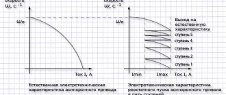
is based on maintaining a constant ratio (U/f) in the operating speed ranges, during which, as can be seen from the formula, only the magnitude of the supply voltage and its frequency are controlled. - With the vector control method,
control is carried out not only over the magnitude and frequency, but also over the phase of the supply voltage. In other words, the angle and magnitude of the so-called spatial vector, which rotates with the frequency of the motor field, is controlled.
Scalar control is most applicable in electric drives of small complexity due to its relative simplicity and the minimum set of functional parameters required for operation. Suitable for applications where it is necessary to maintain a constant (with limited range and accuracy, compared to vector) of a certain process value, and where there are no large dynamic loads.
The vector control method, relative to the scalar control method, has greater performance, range and control accuracy, including at low engine speeds, which covers almost all the shortcomings of the scalar control principle.
One or another control method is selected depending on the requirements specified for the technological process - the depth and accuracy of control, the need to control the torque on the motor shaft, the state of the drive during transient processes - during start/stop, acceleration, braking.
Forms and diagram of vector control
All existing vector engine control systems can be divided into two groups:
- Sensor The engine control unit has speed feedback with it, using the corresponding sensors located on the shaft,
- Sensorless. These are systems that operate without speed sensors on the main shaft.
Sensor systems are more complex, since the control accuracy is 1:10000. Sensorless systems operate at a level of no more than 1:100. All frequency generators, taking into account the level of interference generated, are installed in central or separate cabinets.
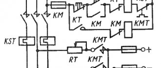
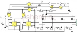
If we present all of the above as a visual diagram, we get something like this:
Here you can see such key components of the control system as:
- AD is actually an asynchronous motor (object of control),
- BRP – logical block of regulators for equation variables,
- BVP is a logical block responsible for calculations based on variables,
- BZP is a block that specifies the values of variables,
- DS – speed sensor on the motor shaft,
- AIN PWM – pulse amplitude/pulse width modulation unit.
What is shown in the diagram as blocks is, in practice, just parametric elements of the control circuit, which is implemented on a microcontroller. Accordingly, the controller itself and accompanying actuators are mounted in an electrical cabinet. For proper installation, a technological map is being developed.