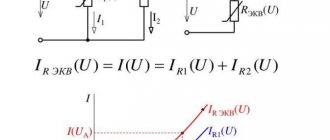
Regulations
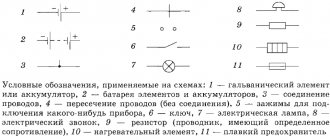
Taking into account the large number of electrical elements, a number of normative documents have been developed for their alphanumeric (hereinafter referred to as BO) and conventional graphic designations (UGO) to eliminate discrepancies. Below is a table showing the main standards.
Table 1. Standards for graphic designation of individual elements in installation and circuit diagrams.
| GOST number | Short description |
| 2.710 81 | This document contains GOST requirements for BO of various types of electrical elements, including electrical appliances. |
| 2.747 68 | Requirements for the dimensions of displaying elements in graphical form. |
| 21.614 88 | Accepted codes for electrical and wiring plans. |
| 2.755 87 | Display of switching devices and contact connections on diagrams |
| 2.756 76 | Standards for sensing parts of electromechanical equipment. |
| 2.709 89 | This standard regulates the standards in accordance with which contact connections and wires are indicated on diagrams. |
| 21.404 85 | Schematic symbols for equipment used in automation systems |
It should be taken into account that the element base changes over time, and accordingly changes are made to regulatory documents, although this process is more inert. Let's give a simple example: RCDs and automatic circuit breakers have been widely used in Russia for more than a decade, but there is still no single standard according to GOST 2.755-87 for these devices, unlike circuit breakers. It is quite possible that this issue will be resolved in the near future. To keep abreast of such innovations, professionals monitor changes in regulatory documents; amateurs do not have to do this; it is enough to know the decoding of the main symbols.
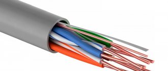
Requirements for the material and cross-section of cables of secondary metering circuits. Marking of cable cores.
14>
Scope of adjustment work in metering circuits on a disconnected installation. Switching devices in meter connection circuits. Installation of test blocks and test adapter boxes
Rules for the design of electrical installations PUE [1] require:
1.5.32. Electrical wiring to meters must meet the requirements given in Chapter. 2.1 and 3.4.
2.1.31. Electrical wiring must allow easy recognition along the entire length of the conductors by color:
• blue color - to indicate the zero working or middle conductor of the electrical network;
• two-color combination of green and yellow - to indicate the protective or neutral protective conductor;
• a two-color combination of green and yellow along the entire length with blue marks at the ends of the line, which are applied during installation - to indicate the combined neutral working and neutral protective conductors;
• black , brown , red , purple, gray, pink, white, orange, turquoise - to indicate the phase conductor.
1.5.33. The presence of rations in the electrical wiring to the settlement meters is not allowed.
1.5.34. The cross-sections of wires and cables connected to meters must be taken in accordance with 3.4.4 (see also 1.5.19).
3.4.4. According to the condition of mechanical strength: the cores of control cables for screw connection to the terminals of panels and devices must have a cross-section of at least 1.5 mm2 for copper and 2.5 mm2 for aluminum; for current circuits - 2.5 mm2 of copper and 4 mm2 for aluminum.
1.5.19. The cross-section and length of wires and cables in the voltage circuits of the calculated meters are selected in such a way that the voltage loss in these circuits is no more than 0.25% of the rated voltage when powered by a voltage transformer of accuracy class 0.5 and no more than 0.5% when powered by voltage transformer accuracy class 1.0. The voltage loss to the technical metering meters should be no more than 1.5%.
When connecting aluminum wires to the meter, the following rules must be observed:
the contact surface of the conductor is cleaned with a steel brush or file and covered with a layer of neutral technical petroleum jelly. Before connecting, contaminated Vaseline is removed from the conductor and a thin layer of Vaseline is immediately applied instead; The screws are tightened in two steps. First, tighten without jerking with the maximum permissible force, then the tightening is greatly weakened (but not completely), after which a secondary, final tightening is performed with normal force; Accounting chains are serviced only by personnel assigned to them. To block access to them for other persons, the accounting chains are sealed. The clamping box of the meter and its clamp assembly, adapter box or test block are subject to sealing.
3.4.9. Secondary circuit cables, cable cores and wires connected to terminal assemblies or devices must be marked.
The minimum cross-section of the conductor is limited by the condition of mechanical strength, the maximum should not exceed 10 mm2. If, due to voltage loss, a conductor of a larger cross-section is required, then to connect it, lugs must be soldered or special adapter clamps must be used.
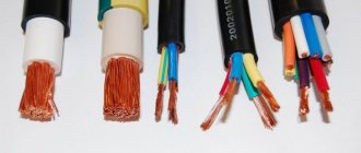
The cutting of cables with rubber core insulation must be protected from exposure to light and air, which destroys the rubber. For this purpose, a vinyl chloride tube is used.
Operational maintenance of meters includes such work as checking the correctness of switching on, checking with standard instruments, and replacing meters. Typically, the current circuits of the meters are connected through adapter terminals. It is necessary that the design of the adapter clamps ensures convenient performance of these works. Adapter clamps must be suitable for short-circuiting current circuits, disconnecting current and voltage circuits in each phase, and connecting devices without disconnecting wires. For metering circuits, an independent row of clamps or a separate section in the general row of clamps is allocated.
If the calculated electricity metering is carried out at the consumer's substation, then the use of intermediate terminal assemblies is not recommended, or they are covered with a casing and sealed.
1.5.35. When installing electrical wiring to connect direct-connection meters, it is necessary to leave the ends of the wires with a length of at least 120 mm near the meters. The insulation or sheath of the neutral wire at a length of 100 mm in front of the meter must have a distinctive color.
1.5.36. For safe installation and replacement of meters in networks with voltages up to 380 V, it must be possible to turn off the meter by switching devices or fuses installed before it at a distance of no more than 10 m. Voltage relief must be provided from all phases connected to the meter.
Current transformers used to connect meters for voltages up to 380 V must be installed after switching devices in the direction of power flow.
1.5.37. Grounding (grounding) of meters and current transformers must be carried out in accordance with the requirements of Chapter. 1.7. In this case, the grounding and neutral protective conductors from meters and current transformers with voltages up to 1 kV to the nearest terminal assembly must be copper.
1.5.38. If there are several connections at the facility with separate electricity metering, the meter panels must contain inscriptions with the names of the connections.
The rules for the design of electrical installations of the Electrical Installation Code in the chapter “Electrical equipment of special installations” require:
It is recommended to place residential meters together with protection devices (circuit breakers, fuses).
7.1.64. To safely replace a meter directly connected to the network, a switching device must be provided in front of each meter to remove voltage from all phases connected to the meter.
Disconnecting devices for removing voltage from settlement meters located in apartments must be located outside the apartment.
After the meter connected directly to the network, a protection device must be installed. If several lines equipped with protection devices extend after the meter, installation of a common protection device is not required.
14>
Date added: 2020-10-14; views: 52; ORDER A WORK WRITING
Find out more:
Types of electrical circuits
In accordance with ESKD standards, diagrams mean graphic documents on which, using accepted notations, the main elements or components of a structure, as well as the connections connecting them, are displayed. According to the accepted classification, there are ten types of circuits, of which three are most often used in electrical engineering:
- Functional, it shows the node elements (depicted as rectangles), as well as the communication lines connecting them. A characteristic feature of this scheme is minimal detail. To describe the main functions of nodes, the rectangles displaying them are signed with standard letter designations. These can be various parts of the product that differ in functionality, for example, an automatic dimmer with a photo relay as a sensor or a regular TV. An example of such a scheme is presented below.
Example of a functional diagram of a television receiver - Fundamental. This type of graphic document displays in detail both the elements used in the design and their connections and contacts. The electrical parameters of some elements can be displayed directly in the document, or presented separately in the form of a table.
Example of a circuit diagram of a milling machine
If the diagram shows only the power part of the installation, then it is called single-line; if all elements are shown, then it is called complete.
Single Line Diagram Example
- Electrical wiring diagrams. These documents use positional designations of elements, that is, their location on the board, method and order of installation are indicated.
Installation diagram of a stationary flammable gas detector
If the drawing shows the wiring of the apartment, then the locations of lighting fixtures, sockets and other equipment are indicated on the plan. Sometimes you can hear such a document called a power supply diagram; this is incorrect, since the latter shows how consumers are connected to a substation or other power source.
Read also: Clamps for wiring in an apartment
Having dealt with the electrical circuits, we can move on to the designations of the elements indicated on them.
Graphic symbols
Each type of graphic document has its own designations, regulated by relevant regulatory documents. Let us give as an example the basic graphic symbols for different types of electrical circuits.
Examples of UGO in functional diagrams
Below is a picture depicting the main components of automation systems.
Examples of symbols for electrical appliances and automation equipment in accordance with GOST 21.404-85
Description of symbols:
- A – Basic (1) and acceptable (2) images of devices that are installed outside the electrical panel or junction box.
- B - The same as point A, except that the elements are located on the remote control or electrical panel.
- C – Display of actuators (AM).
- D – Influence of MI on the regulating body (hereinafter referred to as RO) when the power is turned off:
- RO opening occurs
- Closing RO
- The position of the RO remains unchanged.
- E – IM, on which a manual drive is additionally installed. This symbol may be used for any RO provisions specified in paragraph D.
- F- Accepted mappings of communication lines:
- General.
- There is no connection at the intersection.
- The presence of a connection at the intersection.
UGO in single-line and complete electrical circuits
There are several groups of symbols for these schemes; we present the most common of them. To obtain complete information, you must refer to the regulatory documents; the numbers of state standards will be given for each group.
Power supplies.
To designate them, the symbols shown in the figure below are used.
UGO power supplies on schematic diagrams (GOST 2.742-68 and GOST 2.750.68)
Description of symbols:
- A is a constant voltage source, its polarity is indicated by the symbols “+” and “-”.
- B – electricity icon indicating alternating voltage.
- C is a symbol of alternating and direct voltage, used in cases where the device can be powered from any of these sources.
- D – Display of battery or galvanic power supply.
- E- Symbol of a battery consisting of several batteries.
Communication lines
The basic elements of electrical connectors are presented below.
Designation of communication lines on circuit diagrams (GOST 2.721-74 and GOST 2.751.73)
Description of symbols:
- A – General display adopted for various types of electrical connections.
- B – Current-carrying or grounding bus.
- C – Designation of shielding, can be electrostatic (marked with the symbol “E”) or electromagnetic (“M”).
- D – Grounding symbol.
- E – Electrical connection with the device body.
- F - On complex diagrams, consisting of several components, a broken connection is thus indicated; in such cases, “X” is information about where the line will be continued (as a rule, the element number is indicated).
- G – Intersection with no connection.
- H – Joint at intersection.
- I – Branches.
Designations of electromechanical devices and contact connections
Examples of the designation of magnetic starters, relays, as well as contacts of communication devices can be seen below.
UGO adopted for electromechanical devices and contactors (GOSTs 2.756-76, 2.755-74, 2.755-87)
Description of symbols:
- A – symbol of the coil of an electromechanical device (relay, magnetic starter, etc.).
- B – UGO of the receiving part of the electrothermal protection.
- C – display of the coil of a device with mechanical interlock.
- D – contacts of switching devices:
- Closing.
- Disconnecting.
- Switching.
- E – Symbol for designating manual switches (buttons).
- F – Group switch (switch).
UGO of electric machines
Let us give several examples of displaying electrical machines (hereinafter referred to as EM) in accordance with the current standard.
Designation of electric motors and generators on circuit diagrams (GOST 2.722-68)
Description of symbols:
- A – three-phase EM:
- Asynchronous (squirrel-cage rotor).
- The same as point 1, only in a two-speed version.
- Asynchronous electric motors with phase-phase rotor design.
- Synchronous motors and generators.
- B – Collector, DC powered:
- EM with permanent magnet excitation.
- EM with excitation coil.
Designation of electric motors on diagrams
UGO transformers and chokes
Examples of graphic symbols for these devices can be found in the figure below.
Correct designations of transformers, inductors and chokes (GOST 2.723-78)
Description of symbols:
- A – This graphic symbol can indicate inductors or windings of transformers.
- B – Choke, which has a ferrimagnetic core (magnetic core).
- C – Display of a two-coil transformer.
- D – Device with three coils.
- E - Autotransformer symbol.
- F – Graphic display of CT (current transformer).
Designation of measuring instruments and radio components
A brief overview of the UGO of these electronic components is shown below. For those who want to become more familiar with this information, we recommend viewing GOSTs 2.729 68 and 2.730 73.
Examples of graphic symbols for electronic components and measuring instruments
Description of symbols:
- Electricity meter.
- Picture of an ammeter.
- Device for measuring network voltage.
- Thermal sensor.
- Fixed value resistor.
- Variable resistor.
- Capacitor (general designation).
- Electrolytic capacity.
- Diode designation.
- Light-emitting diode.
- Image of a diode optocoupler.
- UGO transistor (in this case npn).
- Fuse designation.
UGO lighting devices
Let's look at how electric lamps are displayed on a circuit diagram.
An example of how light bulbs are indicated on diagrams (GOST 2.732-68)
Description of symbols:
- A – General image of incandescent lamps (LN).
- B – LN as a signaling device.
- C – Typical designation of gas-discharge lamps.
- D – High-pressure gas-discharge light source (the figure shows an example of a design with two electrodes)
Designation of elements in the electrical wiring diagram
Concluding the topic of graphic symbols, we give examples of displaying sockets and switches.
An example of an image on the wiring diagrams of flush-mounted sockets
How sockets of other types are depicted is easy to find in the regulatory documents that are available on the Internet.
Designation of flush-mounted switches
Designation of sockets and switches
Letter designations
In electrical diagrams, in addition to graphic symbols, alphabetic symbols are also used, since without the latter, reading the drawings will be quite problematic. Alphanumeric marking, just like UGO, is regulated by regulatory documents, for electrical this is GOST 7624 55. Below is a table with BO for the main components of electrical circuits.
Letter designations of main elements
Unfortunately, the size of this article does not allow us to provide all the correct graphic and letter symbols, but we have indicated regulatory documents from which all the missing information can be obtained. It should be taken into account that current standards may change depending on the modernization of the technical base, therefore, we recommend monitoring the release of new additions to regulations.
Read also: Diode 10 ampere 12 volt
General provisions. The marking (designation) of secondary circuits serves to identify them in the electrical circuit. Circuit markings are carried out on diagrams and at the ends of physical conductors connected to product terminals. It is performed in Arabic numerals, and in some cases with a letter prefix made from capital letters of the Latin alphabet.
Sections of circuits are designated regardless of the symbols of the terminals of the devices to which the circuit conductors are connected. Sections of circuits separated by device contacts, relay windings, resistors, capacitors and other elements are considered different, therefore they have different markings. Sections of circuits converging in one circuit node have the same markings, while the circuit marking does not change when passing through the clamps.
The complete circuit often includes individual complete devices that have factory-labeled circuits. In these cases, in order to harmonize the markings adopted in the complete scheme with the factory markings, the factory marking is indicated in brackets near the main marking
With the horizontal method of depicting circuits in the diagram, markings are placed above the image of the circuits, and the numbers of the device terminals are placed under the image of the circuits. Branching sections of the circuit are marked sequentially from the power source (circuit breaker, fuses) from left to right in the direction from top to bottom.
With the vertical method of depicting circuits in the diagram, the markings are placed to the left of the circuit image, and the terminal numbers are to the right; the branching sections of the chain are marked from top to bottom in the direction from left to right.
All secondary circuits of one installation unit (for example, switches of a three-winding transformer) must have different designations. The designations of circuits of similar installation groups are usually performed in the same way. If in the diagram there are sections of circuits of different mounting units with the same markings, then to distinguish them, the markings are supplemented with an index characterizing the chain’s belonging to a specific mounting unit. The distinctive index is placed in front of the circuit designation and separated from it by a dividing line. This index can be the number of the installation unit or the number of the circuit element (for example, 1 – 205, 2 – 205, 3 – 205)
Marking in DC control circuits. DC circuits are marked with numbers taking into account the polarity of the circuits. Sections of circuits with positive polarity are designated by odd numbers, and sections of negative polarity by even numbers. For example, the marking of a circuit consisting of two series-connected contacts and a relay winding will be done as follows: 1 (plus) - contact - 5 - contact - 7 - relay winding - 2 (minus). Sections of circuits that change their polarity during operation or do not have a clearly defined polarity (for example, series-connected relay windings, resistors, capacitors, etc.) can be designated by any numbers: even or odd.
The numbers allocated for marking control circuits, relay protection and alarm systems are divided into groups of one hundred numbers each: 1 - 99; 101 – 199; 201 – 299; 301 – 399; 401 – 499; 501 – 599, etc. To mark circuits fed through individual protective devices, different groups of numbers are used. If the number of numbers in one group is not enough to mark the circuits, use two or more groups of numbers that are not occupied to designate the circuits of a given installation unit, or use four-digit designations, adding numbers 1, 2, 3, etc. in front. For example, in addition to the markings 201-299, you can use 1201-1299; 2201 -2299.
If the installation unit includes several switching devices, then groups of numbers for marking their control circuits are selected in accordance with the serial number of these devices. For example, for the control circuits of switch Q1 of a three-winding transformer the markings are accepted as 101 - 199, for Q2 - 201 - 299, for Q3 - 301 - 399. It is allowed to use the same markings for identical circuits if the possibility of their passage in common cables or connection to the same row of terminals is excluded ( for example, circuits of electromagnets for turning on oil switches).
If the installation unit includes only one switching device, then to mark its control circuits, select a group of numbers 1 - 99, regardless of its serial number.
Marking of relay protection circuits powered by individual auxiliary current circuit breakers is usually carried out in groups of numbers 01 - 099 or F1 - F99 (F - protection). The same designation is often used for protection circuits powered by circuit breakers common to control circuits (for unification).
To mark the control circuits of devices with phase-by-phase drives, the same numerical designations are used with the addition after the numerical part of a letter characterizing the phase of the device (without a space). For example, ZZA, 33V, ZZS are phase-by-phase tripping circuits of the VVB 500 circuit breaker.
Circuits of systems for separate technological purposes can be marked with a group of numbers 1 - 99 with the addition of the letter code assigned to this system before the numerical part. For example, T1 - T99 are telemechanics circuits, U1 - U99 are communication circuits.
Recommendations for the distribution of markings across individual circuits are given in Table 1.
Marking in AC control circuits. Marking of alternating current circuits is carried out in successive numbers without dividing into even and odd, with the addition of a phase (A, B, C) or neutral (N) letter designation before the numerical part. If phase indication is not required (for example, in control circuits using alternating operating current), then the letter index can be omitted.
Before the numerical part of the marking of voltage circuits connected to additional windings of voltage transformers, add the letters H, U, K or F.
The numbers allocated for marking, as with constant operating current, are divided into groups of hundreds. Each of these groups of numbers is usually used to mark circuits of one circuit, powered by separate circuit breakers or fuses.
Table 1. Distribution of groups of numbers for marking DC circuits
Groups of numbers for marking circuits within one installation unit
Installation of electrical installations - Marking circuits in electrical diagrams
Page 2 of 83
The letter symbols of the elements included in the circuit, according to GOST 2.710-81, must be written in Latin letters (Fig. 1.1). This decision was made in connection with the constant expansion of international relations in the field of design, installation and operation of electrical installations.
Rice. 1.1. Marking of power circuits in circuits (GOST 2.710-81): a - alternating current; 6 - direct current To identify conductors, determine their purpose and the position of individual sections of the circuit in electrical circuits, markings are used. Sections of the circuit separated by device contacts, relay windings, instruments, machines and other elements receive different markings. Sections of the circuit passing through detachable, detachable or non-demountable contact connections, as a rule, receive the same markings. If necessary, for such sections of the circuit it is allowed to add serial numbers or designations of devices (units) to the marking, separating them with a hyphen, and for sections of the circuit passing through detachable
Rice. 1 2 Marking of control, protection, measurement circuits (GOST 2 710-81): a - direct current; b - alternating current (current transformer circuits) contact connections, assign different markings. The circuits in the diagrams are marked regardless of the numbering of the input and output terminals of machines, devices, instruments, and relays. The sequence of circuit markings is taken from the input of the power source to the consumer, and the branching sections of the circuit are marked on the diagrams from top to bottom and from left to right. Arabic numbers and capital letters are used for marking. Numbers and letters are written in the same size. When marking circuits, it is allowed to leave reserve numbers. AC power circuits are marked with letters indicating phases and sequential numbers. In three-phase AC circuits, the phases are marked: A, B, C and N, in two-phase circuits - A, B\B, C; C, L, and in single-phase - A, N; B, N; C, N (Fig. 1.1, a). In DC power circuits, sections of circuits with positive polarity are marked with odd numbers, and sections of negative polarity with even numbers (Fig. 1.1,6). The input and output sections of the circuit are marked with polarity: plus (+) and minus (-). The middle conductor is designated by the letter N or M. It is allowed to mark DC power circuits with sequential numbers. Control, protection, signaling and measurement circuits are marked with sequential numbers within the product and connection (Fig. 1.2,a). It is allowed to put down symbols before marking that characterize the functional purpose of the circuit. In Fig. 1.2, and the marking sequence is set from plus to minus (for example, the windings of an electric machine Ml are marked 4-5, contactor K2 is marked 6-7, etc.). The branches are marked from top to bottom.
- Back
- Forward