TECHNICAL REQUIREMENTS
2.1. Wires must meet the requirements of GOST 26445 and the requirements of this standard.
Wires are manufactured in accordance with the requirements of this standard according to design and technological documentation approved in the prescribed manner.
(Changed edition, Amendment No. 3).
2.2. Wires are manufactured in climatic versions OM and HL, placement category 2 according to GOST 15150.
2.3. Wires in the HL climate version must comply with the regulatory and technical documentation.
2.2, 2.3. (Changed edition, Amendment No. 3, 4).
2.4. Design requirements
2.4.1. Current-carrying conductors must comply with the requirements of GOST 22483.
The design of the current-carrying conductors must correspond to that indicated in the table. 3, the maximum outer diameters of the current-carrying conductors of the wires are given in Appendix 2.
Table 3
| Brand | Nominal cross-section of current-carrying conductor, mm2 | Class according to GOST 22483 |
| APV, APPV | From 2.0 to 16.0 incl. | 1 |
| 25.0 and above | 2 | |
| PV1, PPV | From 0.5 to 10.0 incl. | 1 |
| 16.0 and above | 2 | |
| PV2 | 2.0 and higher | 2 |
| PVZ | From 0.5 to 1.5 incl. | 2, 3 or 4 |
| » 2,0 » 4,0 » | 4 | |
| 5.0 and above | 3 | |
| PV4 | 0.5 and 0.75 | 5 |
| 1.0 and 1.5 | 4 or 5 | |
| 2.5 and 4.0 | 5 | |
| 6.0 and 10.0 | 4 or 5 |
The minimum number of wires in the current-carrying cores of PV2 wire with sections 16.0; 25.0 and 35.0 mm2 should be 19, sections 50.0 mm2 and more - 37.
(Changed edition, Amendment No. 3, 4).
2.4.2. Wires of the APPV, PPV and PV4 brands must be insulated with polyvinyl chloride plastic compound in one layer, of the APV, PV1, PV2 and PVZ brands - one or two layers. In structures with two-layer insulation in the bottom layer, the use of filled polyvinyl chloride plastic compound is allowed: in this case, the thickness of the bottom layer should not exceed 70% of the total thickness of the insulation.
Wires of the PPV and APPV brands with conductors laid parallel in one plane must be insulated with a dividing tape base.
(Changed edition, Amendment No. 3).
2.4.3. The nominal insulation thicknesses, depending on the cross-section, must correspond to those indicated in the table. 4.
The lower limit deviation from the nominal thickness of the wire insulation should be 0.1 mm + 10% of the values indicated in the table. 4.
Table4
| Nominal core cross-section, mm2 | Nominal insulation thickness, mm |
| From 0.5 to 1.0 incl. | 0,6 |
| 1.2 and 1.5 | 0,7 |
| From 2.0 to 6.0 incl. | 0,8 |
| » 8,0 » 16,0 »• | 1,0 |
| 25.0 and 35.0 | 1,2 |
| 50.0 and 70.0 | 1,4 |
| 95.0 and 120.0 | 1,6 |
Note. For PV1 grade wire with a cross-section of 1.0 mm2, used for installation in pipes, the nominal insulation thickness should be 0.7 mm, and the letter “y” (PV1u) is added to the wire grade.
The upper limit deviation from the nominal thickness is not standardized.
There should be no dents on the wire insulation that would take the insulation thickness beyond the lower limit deviations, and no local thickenings beyond the maximum dimensions.
It is allowed to repeat the configuration of the current-carrying core on the insulation surface within the permissible deviations of the wire dimensions.
(Changed edition, Amendment No. 3, 4).
2.4.4. The nominal thickness of the dividing tape base of wires of the APPV and PPV brands should be 0.50 mm, the nominal width - 1.0 mm.
The lower limit deviation from the nominal width, the lower and upper deviation from the nominal thickness of the strip base is 0.2 mm, the upper limit deviation from the nominal width is not standardized.
2.4.5. The maximum external dimensions of wires of the PPV and APPV brands must correspond to those indicated in the table. 5, wires of the APV, PV1, PV2, PVZ and PV4 brands - table. 6.
Table 5
| Number and nominal cross-section of cores, P x mm2 | Maximum external dimensions, mm | Number and nominal cross-section of cores, n X mm2 | Maximum external dimensions, mm | ||
| thickness | width | thickness | width | ||
| 2 x 0.75 | 2,6 | 6,4 | 3 X 0.75 | 2,6 | 10,2 |
| 2 x 1.0 | 2,8 | 6,8 | 3 x 1.0 | 2,8 | 10,8 |
| 2 x 1.2 | 3,1 | 7,4 | 3 x 1.2 | 3,1 | 11J |
| 2 x 1.5 | z, z | 7,8 | 3 x 1.5 | 3,3 | 12,3 |
| 2×2,0 | 3,7 | 8,6 | 3 x2.0 | 3,7 | 13,5 |
| 2 x 2.5 | 3,9 | 9,0 | 3 x 2.5 | 3,9 | 14,1 |
| 2 x 3.0 | 4,0 | 9,2 | 3 x 3.0 | 4,0 | 14,4 |
| 2×4,0 | 4,4 | 10,0 | 3 x 4.0 | 4,4 | 15,6 |
| 2×5,0 | 4,6 | 10,4 | 3 x 5.0 | 4,6 | 16,2 |
| 2×6,0 | 4,9 | 11,0 | 3 x 6.0 | 4,9 | 17,1 |
Table 6
| Nominal cross-section of cores, mm2 | Maximum outer diameter, mm, of wire grades | |||
| APV, PV1 | PV2 | PVZ | PV4 | |
| 0,5 | 2,4 | _ | 2,6 | 2,6 |
| 0,75 | 2,6 | — | 2,8 | 2,8 |
| 1,0 | 2,8 | — | 3,0 | 3,0 |
| 1,2 | 3,1 | — | z, z | — |
| 1,5 | 3,3 | — | 3,4 | 3,5 |
| 2,0 | 3,7 | 3,7 | 3,7 | — |
| 2,5 | 3,9 | 4,2 | 4,2 | 4,2 |
| 3,0 | 4,0 | 4,4 | 4,4 | — |
| 4,0 | 4,4 | 4,8 | 4,8 | 4,8 |
| 5,0 | 4,6 | 5,2 | 5,2 | — |
| 6,0 | 4,9 | 5,4 | 6,3 | 6,3 |
| 8,0 | 5,8 | 6,3 | 7,0 | — |
| 10,0 | 6,4 | 6,8 | 7,6 | 7,6 |
| 16,0 | 8,0 | 8,0 | 8,8 | — |
| 25,0 | 9,8 | 9,8 | 11,0 | — |
| 35,0 | 11,0 | 11,0 | 12,5 | — |
| 50,0 | 13,0 | 13,0 | 14,5 | — |
| 70,0 | 15,0 | 15,0 | 17,0 | — |
| 95,0 | 17,0 | 17,0 | 19,0 | — |
| 120,0 | 19,0 | — | — | — |
2.4.4, 2.4.5. (Changed edition, Amendment No. 3).
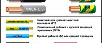
2.4.6. Wires must be made in different colors. The coloring must be solid or done by applying two longitudinal stripes on natural-colored insulation, located diametrically.
The bottom layer of insulation can be produced in different colors. It is not allowed to produce tropical wires in white and natural colors.
For single-core wires used only for grounding purposes, the insulation should be green-yellow. Moreover, on any section of wire 15 mm long, one of these colors must cover at least 30, but not more than 70% of the surface of the wire, and the other color must cover the rest.
The color of continuous insulation or applied longitudinal stripes must be specified in the order and have the following designations:
Table 7
| Color | Designation |
| White, natural or gray | B |
| Yellow or orange or purple | AND |
| Red or pink | TO |
| Blue or cyan | With |
| Green | 3 |
| Brown | Kch |
| Black | h |
| Green-yellow | 3-F |
If there is no indication of a specific color in the order, the manufacturer produces wires of a color at its discretion; however, it is allowed to produce wires with insulation of transitional and mixed colors other than the colors indicated in the table. 7, with the designation “BC” in a volume of no more than 10% of the batch.
(Changed edition, Amendment No. 3, 4).
2.4.7. The construction length of the wires must be at least 100 m. No more than 10% of wire sections with a length of at least 20 m for wires of all brands and at least 5 m for wire of the PV4 brand are allowed in a batch.
2.4.8. The insulation must adhere tightly to the conductor and be removed without damage.
2.4.9. The estimated weight of the wires is indicated in Appendix 3.
2.4.10. The materials used for the manufacture of wires must comply with:
copper electrical wire grade MM - TU 16.K71-087;
aluminum wire grades AM and APT - TU 16.K71-088;
polyvinyl chloride plastic compound grades I40-13A, I40-14 - GOST 5960;
plastic compound polyvinyl chloride grade IT-90, plastic compound
polyvinyl chloride filled grades IM-20-7 and
IM-30-9 - regulatory and technical
documentation.
It is allowed to use plastic compounds of other brands that meet the requirements of GOST 5960 for the above brands.
It is also allowed for combined technological processes of annealing and insulating single-wire cores to use MT grade copper wire according to TU 16.K71-087 and AT grade aluminum wire according to TU 16.K71-088.
2.5. Electrical Requirements
2.5.1. The electrical resistance of current-carrying conductors to direct current, recalculated per 1 km of length and a temperature of 20 ° C, must correspond to:
upon acceptance and delivery - to the values specified in GOST 22483;
for the period of operation and storage - no more than 120% of the values specified in GOST 22483.
2.4.7—2.5.1. (Changed edition, Amendment No. 3).
2.5.2. Wires must withstand the voltage test upon acceptance and delivery according to category EI-1 GOST 23286 with immersion in water without preliminary exposure in it or according to category EI-2 GOST 23286, for the period of operation and storage - at least 50% of those standardized for category EI-1 with immersion in water without preliminary exposure to it.
(Changed edition, Amendment No. 4).
2.5.3. After 24 hours in water, the wires must withstand a test with an alternating voltage of 2500 V, frequency 50 Hz for 15 minutes.
(Changed edition, Amendment No. 3).
2.5.4. The electrical resistance of wire insulation at a temperature of 20 °C, recalculated per 1 km of length, must be, Ohm, not less than:
upon acceptance and delivery - 1-106; for the period of operation and storage - 1104; for wires with the HL index: upon acceptance and delivery - 8104; for the period of operation and storage - 1103.
(Changed edition, Amendment No. 3, 4).
2.5.5. The electrical resistance of the wire insulation, recalculated per 1 km of length and measured in water at a temperature of 70 “C, must correspond to the values indicated in the table. 8.
Table 8
| Nominal cross section | Insulation resistance, kOhm, not less, wire brands | ||
| current-carrying cores, mm* | APV, APPV, PPV, PV1 | PV2 | PVZ, PV4 |
| 0,5 | 15 | 13 | |
| 0,75 | 13 | — | 11 |
| 1,0 | 11 | — | 10 |
| 1,2 | 11 | — | 10 |
| 1,5 | AND | — | 10 |
| 2,0 | 10 | 10 | 9,0 |
| 2,5 | 10 | 10 | 9,0 |
| 3,0 | 9,0 | 9,0 | 8,0 |
| 4,0 | 9,0 | 9 | 7,0 |
| 5,0 | 7,7 | 7,1 | 6,5 |
| 6,0 | 7,0 | 7 | 6,0 |
| 8,0 | 7,0 | 6,5 | 5,6 |
| 10,0 | 7,0 | 6,5 | 5,6 |
| 16,0 | 5,0 | 5,0 | 4,6 |
| 25,0 | 5,0 | 5,0 | 4,4 |
| 35,0 | 4,0 | 4,0 | 3,8 |
| 50,0 | 4,5 | 4,5 | 3,7 |
| 70,0 | 4,0 | 4,0 | 3,2 |
| 95,0 | 4,0 | 4,0 | 3,2 |
| 120,0 | 3,2 |
2.6. Requirements for resistance to external influences
2.6.1. The wires must be resistant to sinusoidal vibration with a frequency range from 1 to 2000 Hz with an acceleration amplitude of up to 200 m-s-2; degree of hardness XII.
2.6.2. The wires must be resistant to acoustic noise with a frequency range from 50 to 10,000 Hz at a sound pressure level of 160 dB, severity level IV.
2.6.3. The wires must be resistant to single-action mechanical shock with a peak impact acceleration of 15,000 m-s-2, with a duration of impact acceleration of 0.1-2 ms; degree of hardness VII.
2.6.4. The wires must be resistant to repeated mechanical shocks with a peak shock acceleration of 1500 m s-2 with a shock acceleration duration of 1-5 ms; degree of hardness IV.
2.6.5. The wires must be resistant to linear acceleration up to 1000 m s-2, hardness degree IV.
2.6.6. Wires must be resistant to low atmospheric pressure
5.3-104 Pa.
2.6.7. The wires must be resistant to high atmospheric pressure of 29.4-104 Pa.
2.6.8. The wires must be resistant to temperatures of 70 “C.
2.6.9. The wires must be resistant to low operating temperatures down to minus 50 °C.
2.6.10. The wires must be resistant to relative air humidity of 100% at a temperature of 35 ° C; degree of hardness III.
2.6.11. The wires must be resistant to mold.
2.6.12. Wires must not spread fire.
2.6.13. Wire insulation must be resistant to cracking at a temperature of 150 °C and deformation at a temperature of 70 °C.
2.7. Mechanical requirements
2.5.5—2.7. (Changed edition, Amendment No. 3).
2.7.1. Before and after aging, the tensile strength of the insulation must be at least 12.5 MPa, for wires with a CL index of at least 8.5 MPa, the relative elongation must be at least 125%; after aging, these parameters should not decrease by more than 20% of the values obtained in the original state.
(Changed edition, Amendment No. 3, 4).
2.7.2. Wires with solid cores must be resistant to bending at an angle of 90° to the right and left of the original position. The number of cycles must be at least 10 with a bend radius equal to five times the outer diameter of the wire or the thickness of the flat wires.
(Changed edition, Amendment No. 3).
2.7.3. Wires must be resistant to bending or elongation testing, and wires of grades PV1 and PV2 must also be resistant to impact at a temperature of minus 15 °C.
(Changed edition, Amendment No. 4).
2.8. Reliability requirements
2.8.1. The service life of the wires is at least 15 years.
2.8. 2.8.1. (Changed edition, Amendment No. 3).
2.9—2.17. (Excluded, Amendment No. 3).
GOST 6323-79
WIRES WITH POLYVINYL CHLORIDE INSULATION FOR ELECTRICAL INSTALLATIONS
TECHNICAL CONDITIONS GOST 6323-79 (ST SEV 587-87)
This standard applies to wires with copper and aluminum or copper-clad aluminum conductors with polyvinyl chloride plastic insulation, used for electrical installations for stationary installation in lighting and power networks, as well as for installation of electrical equipment, machines, mechanisms and machine tools for rated voltages up to 450 V (for networks up to 450/750 V) with a frequency of up to 400 Hz or constant voltage up to 1000 V. The standard establishes requirements for wires for the needs of the national economy and export, including to countries with tropical and cold climates. (Changed edition, Amendment No. 3, 4)
BRANDS AND SIZES 1.1.
Brands, names, design diagrams and preferred methods of laying or installing wires must correspond to those indicated in the table. 1.
Table No. 1
| Designation | Name | Scheme designs | Preferred laying or installation methods |
| Automatic reclosing | Wires with aluminum or aluminum clad copper conductor with polyvinyl chloride insulation. | For installation in steel pipes, hollow channels of building structures, on trays, etc., for installation of electrical circuits | |
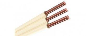
| PV1 | Wire with copper core and PVC insulation | Same | |
| PV2 | Wire with copper core with PVC insulation, flexible | For installation of sections of electrical circuits where wire bends are possible | |
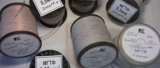
| PV3 | Wire with copper core with polyvinyl chloride insulation of increased flexibility | Same | |
| PV4 | PVC-insulated copper wire, particularly flexible | For installation of sections of electrical circuits where frequent bending of wires is possible. | |
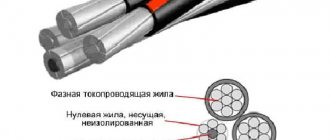
| APPV | Wire with aluminum or aluminum copper-clad conductors with PVC insulated, flat with dividing base | 0 | For non-flexible installation |
| PPV | Wire with copper cores with PVC insulation, flat with separating base | 0 | Same |
The letters “ХЛ” are added through a hyphen to the brand of cold-grade wire. OKP codes are given in Appendix 1.
1.2. The nominal cross-section of the cores and their number in the wire must correspond to those indicated in the table. 2.
| table 2 | |||||||||||||||||||||||||||||||||||||||||||||||||||||||||||||||||||||||||||||||||||||||||||||||||||||||||||||||||||||||||||||||||||||||||||||||||||||||||||||||||||||||||||||||||||||||||||||||||||||||||||||||||||||||
| .An example of a symbol for a wire of the PV1 brand with a copper core, with polyvinyl chloride insulation, cross-section 2.5 mm2, natural, white or gray color PV1 2.5 B GOST 6323-79; APPV brand with aluminum conductors with polyvinyl chloride insulation, flat, with dividing bases, cross-section 2.5 mm, A APPV 2×2.5 GOST 6323-79; grade PV3 with copper core with polyvinyl chloride insulation, cross-section 2.5 mm, yellow or orange color PV3 2.5 ZH GOST 6323-79; 2 grade PV3 with copper core with polyvinyl chloride insulation, cross-section 2.5 mm, cold version, transitional or mixed colors PV3-HL 2.5 BC GOST 6323-79. 1.1. 1.2. (Changed edition, Amendment No. 3, 4). 1.3, 1.4, 1.4a, 1.5. (Excluded, Amendment No. 3). 2. TECHNICAL REQUIREMENTS 2.1. Wires must meet the requirements of GOST 26445 and the requirements of this standard. Wires are manufactured in accordance with the requirements of this standard according to design and technological documentation approved in the prescribed manner. (Changed edition, Amendment No. 3). 2.2. Wires are manufactured in climatic versions OM and HL, placement category 2 according to GOST 15150. 2.3. Wires in the HL climate version must comply with the regulatory technical documentation. 2.2, 2.3. (Changed edition, Amendment No. 3, 4). 2.4. Design requirements 2.4.1. Current-carrying conductors must comply with the requirements of GOST 22483. The design of the current-carrying conductors must correspond to that indicated in the table. 3, the maximum outer diameters of the current-carrying conductors of the wires are given in Appendix 2.
| |||||||||||||||||||||||||||||||||||||||||||||||||||||||||||||||||||||||||||||||||||||||||||||||||||||||||||||||||||||||||||||||||||||||||||||||||||||||||||||||||||||||||||||||||||||||||||||||||||||||||||||||||||||||
ACCEPTANCE RULES
3.1. The rules for acceptance of wires must comply with GOST 26445 and this standard.
3.2. Acceptance tests
3.2.1. The volume of a batch of wires is no less than 300 m and no more than 100 km.
3.2.2. The composition of the tests and the sequence of their conduct within each group must correspond to those indicated in table. 9.
Table 9
| Items | ||||
| Test group | Type of test or inspection | technical requirements | control methods | |
| GOST 6323 | GOST 6323 | GOST 26445 | ||
| C—1 | Checking the appearance | 2.4.2; 2.4.3; 2.4.6 | — | 4.2.1 |
| S-2 | Checking design dimensions | 2.4.1; 2.4.2; 2.4.3—2.4.7 | 4.2.1 | — |
| S—3 | Voltage test | 2.5.2 | 4.3.1 | — |
| C—4 | Checking the electrical resistance of current-carrying conductors | 2.5.1 | — | 4.3.1 |
| S—5 | Checking labeling and packaging | 5.2; 5.3 | — | 4.6.1 |
| S-6 | Bend strength test | 2.7.2 | 4.5.1 | — |
3.2.3. Tests for groups C-1, C-2, C-4 and C-6 are carried out sequentially on one sample, for groups C-3 and C-5 - on independent samples.
3.1—3.2.3. (Changed edition, Amendment No. 3).
3.2.4. To carry out tests in groups, selective single-stage control is used with an acceptance number C = 0.
The sample size for groups S-1, S-2, S-4 and S-5 is 5%, for group S-3 - for category EI-2 - 100%, for category EI-1 - 2%, but not less three bays or construction lengths, for group C-6 - three samples from batches.
(Changed edition, Amendment No. 3, 4).
3.3. Periodic testing
3.3.1. The composition of the tests and the sequence of their conduct within each group must correspond to those indicated in table. 10.
Table 10
| Items | ||||
| Test group | Type of test or inspection | technical requirements | control methods | |
| GOST 6323 | GOST 6323 | GOST 26445 | ||
| P—1 | AC voltage test | 2.5.3 | 4.3.2 | — |
| Checking the electrical resistance of wire insulation | 2.5.4; 2.5.5 | 4.3.3 | — | |
| Cold resistance test | 2.6.9 | 4.4.5 | — | |
| P—2 | Determination of resistance to cracking and deformation at elevated temperatures | 2.6.13 | 4.4.24 | |
| P—3 | Checking the physical and mechanical properties of insulation | 2.7.1 | — | 4.5.6 |
| I 1 -fc. | Flame retardation test | 2.6.12 | — | 4.4.21 |
3.3.2. Tests are carried out once every 12 months.
3.4. The consumer assesses the compliance of the electrical parameters of the wires with the requirements of this standard (clauses 2.5.2, 2.5.4) during incoming inspection within 12 months from the date of manufacture according to the standards established for the acceptance and delivery of wires.
3.3—3.4. (Changed edition, Amendment No. 3).
3.5, 3.6. (Excluded, Amendment No. 3).
Supply of wires PV 1
You cannot ignore the conditions and requirements for delivery conditions. In addition, attention should be paid to the requirements for acceptance of the wire.
| According to GOST 6323 - 79, wire acceptance should be carried out according to certain rules. And the first item on this list is an external inspection of the wire. It must be marked accordingly, and the wire insulation must not be deformed. |
| Checking the wire cross-section | The next step is to check the design dimensions. It is quite possible to do this yourself. To do this, measure the cross-section of the wire, as well as the suitability of the insulation thickness. |
| At the same stage, they check how freely the insulation is separated from the conductor cores. According to GOST, insulation cut around the entire circumference at a distance of 13 cm from the edge should be removed without effort. |
| Test setup diagram | After this, high-voltage tests of the wire are carried out. We described them in the section on the electrical characteristics of the wire. |
| The next step is to check the electrical resistance of the wire. It should not exceed the standardized values shown in the photo above. However, for high-voltage tests and resistance determinations should be carried out on the same piece of wire. |
| After this, the packaging of the wire is checked and the presence of all the necessary symbols on its tag. The length of the wire, if any, the length of individual pieces of wire, the weight of the coil, the name of the manufacturer and the date of manufacture must be indicated on the coil. |
| Installation for testing wire bending resistance | The final test is the bending resistance test. To do this, take a roller with a diameter equal to 10 wire diameters and run the wire through it. If after this no deformation is detected, then the wire is accepted for use. |
CONTROL METHODS
4.1. Control methods must comply with GOST 26445 and this standard.
4.2. Inspection of wires for compliance with design requirements
4.1. 4.2. (Changed edition, Amendment No. 3).
4.2.1. The structural dimensions of the wires are checked according to GOST 12177. It is not allowed to determine the insulation thickness by the difference in the measured values of the outer diameters of the wire and core.
Checking the construction length of wires (clause 2.4.7) is carried out during the production process in accordance with GOST 12177.
The insulation thickness and geometric dimensions of the separate strip base can be measured during the production process with a general-purpose measuring magnifying glass in accordance with GOST 25706.
(Changed edition, Amendment No. 3, 4).
4.2.2. When checking wires for compliance with the requirement of clause 2.4.8 on a sample wire with a length of (130 ± 5) mm from one end at a distance of (25 ± 5) mm on the insulation, a circular cut is made to the core. A small portion of the insulation must be removed by hand, but the rest must not. For flat wires, this test is carried out on one of the cores.
(Changed edition, Amendment No. 4).
4.3. Inspection of wires for compliance with electrical requirements
(Changed edition, Amendment No. 3).
4.3.1. The voltage test (clause 2.5.2) is carried out in accordance with GOST 2990.
(Changed edition, Amendment No. 4).
4.3.2. The voltage test (clause 2.5.3) is carried out on samples with a length of at least 20 m in accordance with GOST 2990.
4.3.3. Measurement of electrical insulation resistance (clauses 2.5.4, 2.5.5) must be carried out after 2 hours in water on wire samples with a length of at least 5 m according to GOST 3345.
When taking measurements, the ends of wires 0.25 m long must be taken out of the water.
4.4. Inspection of wires for compliance with requirements for resistance to external influences
4.4.1. The wires are considered to have passed the tests for compliance with the requirements of paragraphs. 2.6.1—
2.6.5, 2.6.9, if after testing the samples meet the requirements of clause 2.5.2 (for the period of operation and storage).
4.4.2. The wires are considered to have passed the tests for compliance with the requirements of paragraphs. 2.6.6, 2.6.7,
2.6.10, if they meet the requirements of paragraphs. 2.5.2 and 2.5.4 (for the period of operation and storage).
4.4.3. Tests for the influence of external influencing factors should be carried out on wire samples 0.6-1.5 m long.
Before testing, samples of wires of the APV, PV1, APPV and PPV brands are wound onto a rod with a diameter equal to ten times, wires of the PV2, PVZ and PV4 brands - five times the diameter of the wire without applying a tensile load. The number of turns must be at least three.
4.4.4. The test for resistance to elevated temperatures (clause 2.6.8) is carried out according to GOST 20.57.406 (method 201-1) and GOST 25018 on insulation samples removed from wires by holding in a thermostat for 72 hours at a temperature (90± 3) °C.
After removing the samples from the thermostat, they are kept in normal climatic conditions for 1 hour; the indicator of change in tensile strength and elongation at break must be at least 0.5.
4.4.5. The test for resistance to low ambient temperatures (clause 2.6.9) is carried out according to GOST 20.57.406 (method 203-1) without electrical load.
The holding time of samples in the cold chamber is 1 hour.
After removing the samples from the cold chamber, they are kept in normal climatic conditions for 1 hour.
4.4.6. The test for the effects of mold fungi (clause 2.6.11) is carried out according to GOST 20.57.406 (method 214-1) on straightened samples with a length of at least 200 mm.
4.5. Inspection of wires for compliance with mechanical requirements
4.3.2—4.5. (Changed edition, Amendment No. 3).
4.5.1. The test for resistance to bending (clause 2.7.2) is carried out according to GOST 1579. For stranded conductors, three wires from the sample are tested.
(Changed edition, Amendment No. 4).
4.5.2. Testing of wires for compliance with the requirements of clause 2.7.3 is carried out in accordance with GOST 17491.
(Changed edition, Amendment No. 3).
4.6. Control of wires for compliance with reliability requirements
4.6.1. The service life test (clause 2.8.1) is carried out in accordance with the regulatory and technical documentation.
4.6. 4.6.1. (Introduced additionally, Amendment No. 4).
4.7—4.11. (Excluded, Amendment No. 3).
5. LABELING, PACKAGING, TRANSPORTATION AND STORAGE
5.1. Labeling, packaging, transportation and storage must comply with the requirements of GOST 26445 and this standard.
5.2. Marking
5.1, 5.2. (Changed edition, Amendment No. 3).
5.2.1. Wires must have a manufacturer's designation, which must be made in the form of continuous marking of the manufacturer's code and wire brand.
The marking may be printed, embossed or stamped onto the surface of the wire. The distance from the end of the marking to the beginning of the next one should not exceed 500 mm.
On wires of the PPV and APPV brands there should be a mark on one of the outer cores, visible without the use of magnifying devices.
It is allowed to mark wires with cross-sections from 0.5 to 6.0 mm2 inclusive in the form of a distinctive thread or colored stripes, or solid marks.
5.2.2. The label attached to the drum or drum cheek must indicate the number of segments and their length through a plus sign from the top to the bottom layers in meters.
5.2.1. 5.2.2. (Changed edition, Amendment No. 4).
5.3. Package
(Changed edition, Amendment No. 3).
5.3.1. Wires must be wound in coils or on wooden drums in accordance with GOST 5151. No more than three pieces of wire in a coil and winding of more than three pieces of wire on drums are allowed in compliance with the requirements of clause 2.4.7.
Partial covering of drums in accordance with GOST 5151 is allowed.
(Changed edition, Amendment No. 3, 4).
5.3.2. Coils of wires must be wrapped in packaging material or placed in bags or boxes, or in specialized containers for direct deliveries to the consumer, or until 01/01/92 containers that ensure the safety of wires from mechanical damage during transportation.
(Changed edition, Amendment No. 4).
5.4. Transportation and storage
5.4.1. The conditions for transporting wires in terms of exposure to climatic factors must comply with storage conditions 3 according to GOST 15150.
5.4.2. The storage conditions for wires must comply with storage conditions 3 according to GOST 15150.
5.4—5.4.2. (Changed edition, Amendment No. 3).
OPERATING INSTRUCTIONS
6.1. The wires are intended for operation at ambient temperatures down to minus 50 °C and relative air humidity of 100% at a temperature of 35 °C.
Installation of wires must be carried out at a temperature not lower than minus 15 ° C.
The long-term permissible heating temperature of the cores should not exceed 70 °C.
The bending radius during installation must be at least five wire diameters for wires of the PV2, PVZ and PV4 brands and ten diameters for wires of other brands.
Sec. 6. (Changed edition, Amendment No. 3).