The advantages of this method of determining the slip of an electric motor are: the speed of measurements and the ability to carry them out both at a constant and at a changing speed. The disadvantages of this measurement method include the low accuracy of conventional tachometers (error 1–8%) and the difficulty of their calibration. In addition, the tachometer cannot be used when testing low-power electric motors, since friction losses inside the tachometer mechanism represent a noticeable load.
If there is a recess in the center of the shaft, an extension is used, which is put on the tachometer shaft, and the corresponding tip is placed on the extension. If there are no or insufficient centers, a pulley is used, which is pressed by the side surface (rubber ring) to the surface of the rotating shaft.
In accordance with the specific measurement conditions, a device (extension tip) is selected. Before starting measurements, remove grease, dirt, and dust from the center of the recess or shaft surface.
To measure the rotation speed of the electric motor, you must first set the required measurement limit on the tachometer. If the frequency measurement order is unknown, then the measurement should start from the highest limit to avoid damage to the tachometer.
The measurement should be carried out briefly (3 - 5 s), carefully pressing the tip of the tachometer to the rotating shaft with slight pressure so that the axis of the tachometer shaft coincides with the axis of the shaft being measured or, when using a pulley, is parallel to it.
If the slip does not exceed 5%, the rotation speed can be measured by the stroboscopic method using a neon lamp.
A diametrical line is drawn on the end of the engine shaft with chalk. While the engine is running, it is illuminated with a neon lamp, powered from a network of the same frequency as the engine. The observer sees at the end of the shaft not a line, but a star rotating slowly against the direction of rotation of the shaft. The number of rays of the star depends on the number of pole pairs of the motor and on the position of the neon lamp. If the light from both electrodes of the lamp falls on the end of the shaft, the number of rays of the apparent star is equal to 2p. If the end of the shaft with the chalk line is illuminated by only one electrode, the number of rays of the apparent star is equal to the number of pairs of poles.
During a time t (usually 30 s), measured with a stopwatch, the number of rays of the apparent star m passing through the vertical position is counted. Since the number of rays of an apparent star is 2p, the sliding
where f1 is the frequency of the network feeding the neon lamp.
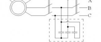
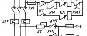
Another version of the stroboscopic method is as follows. One of the disks is fixed on the motor shaft from the end side (Fig. 2). Assemble the diagram (Fig. 3). For a two-pole machine, a disk designated as 2p = 2 is attached to the shaft and illuminated with a neon lamp with a patch electrode.
The rotor rotates asynchronously and lags behind the field, so that the disk is visible slowly rotating in the direction opposite to the rotation of the rotor. If during time t m black sectors pass by a fixed point (arrow mounted on a bearing), the slip value is determined by the expression
The counting of sectors passing by a fixed point should not begin from the moment the stopwatch is started, but from the next passage of the mark.
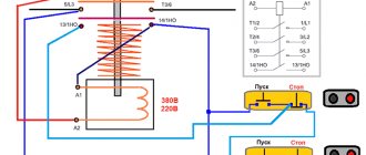
Motor slip detection using an induction coil. This method is based on monitoring the rotation frequency of the rotor dissipation fluxes Fr (Fig. 5), which cross the turns of the induction coil with a frequency proportional to the slip.
Rice. 5. Scheme for measuring rotor slip of an asynchronous electric motor using an induction coil
A sensitive millivoltmeter (preferably with a zero in the middle of the scale) is connected to the coil terminals; the coil is located at the end of the rotor shaft. By turning the coil in different directions, find the position at which maximum oscillations of the instrument needle are observed. Based on the number of complete oscillations k during time t, the slip value is calculated
As an induction coil, you can use a relay or DC contactor coil with 10–20 thousand turns (or wind a coil with at least 3000 turns). To enhance the magnetic flux, a core made from several strips of transformer steel is inserted into the coil. The induction coil method is very simple and suitable for all types of machines.
For asynchronous electric motors with a wound rotor, in addition to the methods described above, slip can be determined using a magnetoelectric ammeter connected to one of the rotor phases, and if there is a non-switchable resistance in the rotor circuit, using a voltmeter connected to the rotor rings. It is recommended to use instruments with a double-sided scale. The slip of an asynchronous electric motor is calculated by the number of complete oscillations of the instrument needle, just as when using the induction coil method.
If you liked this article, share a link to it on social networks. This will greatly help the development of our site!
Don't miss updates, subscribe to our social networks:
Source
How to determine the slip of an asynchronous motor during setup and operation
The advantages of this method for determining the slip of an electric motor are: the speed of measurements and the ability to create them both at a constant and at a changing speed. The disadvantages of this measurement method include the low accuracy of ordinary tachometers (error 1–8%) and the difficulty of their calibration. In addition, the tachometer cannot be used when testing low-power electric motors, because friction losses inside the tachometer mechanism represent a noticeable load.
If there is a recess in the center of the shaft, an extension is used, which is put on the tachometer shaft, and the corresponding tip is placed on the extension. In the absence or deficiency of centers, a pulley is used, which is pressed by the side surface (rubber ring) to the surface of the rotating shaft.
In accordance with certain measurement criteria, a device (extension tip) is selected. Before measurement, remove grease, dirt, and dust from the center of the recess or the surface of the shaft.
To measure the rotation speed of the electric motor, you must first set the required measurement limit on the tachometer. If the frequency measurement order is unknown, then the measurement should start from the highest limit to avoid damage to the tachometer.
How to determine the slip of an asynchronous motor during setup and operation
Slip of induction motor
- the relative difference in the speed of rotation of the rotor and the change in alternating magnetic flux created by the stator windings of an AC motor. Slip can be measured in relative units and as a percentage.
where n is the rotor speed of the asynchronous motor, rpm
n 1 > - the speed of cyclic change of the stator magnetic flux, called the synchronous speed of the motor.
where f is the frequency of the alternating current network, Hz
p is the number of pairs of poles of the stator winding (the number of pairs of coils per phase).
From the last formula it is clear that the motor rotation speed n is practically determined by the value of its synchronous speed, and the latter at a standard frequency of 50 depends on the number of pairs of poles: with one pair of poles - 3000 rpm, with two pairs - 1500 rpm, with three in pairs - 1000 rpm, etc.
What it is
The operating principle of a three-phase asynchronous motor is quite simple. A supply voltage is supplied to the stator winding, which creates a magnetic flux; in each phase it will be shifted by 120 degrees. In this case, the summing magnetic flux will be rotating.
The rotor winding is a closed circuit, an EMF is induced in it and the resulting magnetic flux imparts rotation to the rotor in the direction of movement of the stator magnetic flux. The electromagnetic torque tries to equalize the speed of rotation of the magnetic fields of the stator and rotor.
The value that determines the difference in the rotation speeds of the magnetic fields of the rotor and stator is called slip. Since the rotor of an asynchronous motor always rotates slower than the stator field, it is usually less than unity. Can be measured in relative units or percentages.
It is calculated using the formula:
where n1 is the rotation frequency of the magnetic field, n2 is the rotation frequency of the rotor magnetic field.
Slip is an important characteristic characterizing the normal operation of an asynchronous electric motor.
Three-phase squirrel-cage asynchronous motor
Construction of an asynchronous electric motor
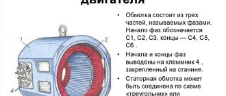
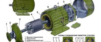
A three-phase asynchronous electric motor, like any electric motor, consists of two main parts - a stator and a rotor. The stator is the stationary part, the rotor is the rotating part. The rotor is placed inside the stator. There is a small distance between the rotor and stator, called an air gap, usually 0.5-2 mm.
Stator
consists of a body and a core with a winding. The stator core is assembled from thin sheet technical steel, usually 0.5 mm thick, coated with insulating varnish. The laminated core design contributes to a significant reduction in eddy currents arising during the process of magnetization reversal of the core by a rotating magnetic field. The stator windings are located in the slots of the core.
Rotor
consists of a core with a short-circuited winding and a shaft. The rotor core also has a laminated design. In this case, the rotor sheets are not varnished, since the current has a low frequency and the oxide film is sufficient to limit eddy currents.
Principle of operation. Rotating magnetic field
The operating principle of a three-phase asynchronous electric motor is based on the ability of a three-phase winding to create a rotating magnetic field when connected to a three-phase current network.
A rotating magnetic field is the basic concept of electric motors and generators.
The rotation frequency of this field, or the synchronous rotation frequency, is directly proportional to the frequency of the alternating current f1 and inversely proportional to the number of pole pairs p of the three-phase winding.
The operating principle of an asynchronous motor.
When voltage is applied to the winding in any of the phases, a magnetic flux is created. It changes parallel to the frequency of the applied voltage. These magnetic fluxes are shifted by 120 degrees in time and space relative to each other. At the same time, the resulting magnetic flux actually turns out to be rotating. In the rotor conductors, the resulting magnetic flux of the stator during rotation creates an emf. There is a closed electrical circuit in the rotor winding in which current arises. Meanwhile, the current, when interacting with the stator magnetic flux, produces a motor starting torque, which tends to direct the rotor in the direction in which the stator magnetic field rotates. When it exceeds the rotor braking torque, the rotor will come into action. At this moment slipping occurs.
Operating modes
The asynchronous type electric motor is a universal mechanism and has several operating modes in terms of operating time:
Continuous mode is the main operating mode of asynchronous devices, which is characterized by constant operation of the electric motor without shutdowns with a constant load. This mode of operation is the most common and is used everywhere in industrial enterprises.
Short-term mode - works until a constant load is achieved for a certain time (from 10 to 90 minutes), without having time to warm up as much as possible. After this it turns off. This mode is used when supplying working substances (water, oil, gas) and other situations.
Periodic mode - the duration of work has a certain value and is turned off at the end of the work cycle. Operating mode start-run-stop. In this case, it can turn off for a time during which it does not have time to cool down to external temperatures and turn on again.
Intermittent mode - the engine does not heat up to its maximum, but also does not have time to cool down to the outside temperature. Used in elevators, escalators and other devices.
Special mode – duration and switching period are arbitrary.
In electrical engineering, there is a principle of reversibility of electrical machines - this means that the device can both convert electrical energy into mechanical energy and perform reverse actions.
Asynchronous electric motors also correspond to this principle and have motor and generator modes of operation.
Motor mode is the main operating mode of an asynchronous electric motor. When voltage is applied to the windings, an electromagnetic torque arises, dragging the rotor with the shaft along with it and, thus, the shaft begins to rotate, the engine reaches a constant speed, performing useful work.
Generator mode - based on the principle of exciting electric current in the motor windings when the rotor rotates. If you rotate the motor rotor mechanically, an electromotive force is generated on the stator windings; if there is a capacitor in the windings, a capacitive current appears. If the capacitance of the capacitor is of a certain value, depending on the characteristics of the engine, then self-excitation of the generator will occur and a three-phase voltage system will arise. Thus, the squirrel-cage electric motor will work as a generator.
ROTOR SLIP
The rotor of an asynchronous motor must always lag behind the rotating magnetic flux. The rotation speed of the flow is usually denoted by p
1, it is constant, since p =
const and
f
1 = const.
The rotation speed of the rotor can be denoted by n
2. The value is called slip m.
Theoretically, the slip changes from 1 to 0 or from 100% to 0, since with a stationary rotor at the first moment of start-up p2
= 0, and if we imagine that the rotor rotates synchronously with the flow, p2
=
n
1. The greater the load on the shaft, the greater the braking torque must be balanced by the greater torque.
The latter is possible only with an increase in I
2, and therefore
E2.
As will be shown below,
E2
increases as
n2
, i.e., as
s
increases. Thus, as the load on the shaft increases, the rotor speed
n2
decreases.
Slip at rated load Sn
for asynchronous motors is from 1 to 6%; the lower figure refers to powerful engines
What determines the amount of slip of an electric motor?
- Typically, slip is relatively small when the motor is running at rated load. For example, when the electric motor operates at 1500 rpm, the slip is 2.7%.
- Induction motors cannot reach synchronous speed even if the mechanism is disconnected. The rotor conductors will never intersect with the magnetic field, there will be no EMF in them, and accordingly there will be no current. In this case, the asynchronous torque will be equal to zero.
- At the moment of start-up, a current corresponding to the network frequency is supplied to the rotor winding. As it accelerates, the frequency of the current will be determined by the slip. In this case, the rotor resistance will depend on the frequency of the current. Inductive reactance will increase as the frequency of the current increases.
- The values of equivalent resistance change in accordance with the laws of physics. If the motor slip decreases, the resistance increases accordingly.
- When the starting torque before the development of sliding is within 0.15, the resistance force decreases slightly. With further work, on the contrary, it quickly decreases. The magnitude of the torque is determined by the corresponding magnitude of the magnetic flux, the incoming current and the shift between the parameters of the EMF and the current in the rotor. The dependence of slip torque and voltage on frequency is established during a study of technical characteristics by electric motor manufacturers.
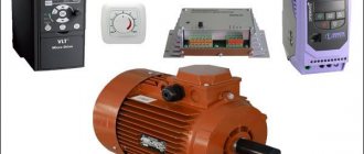
Asynchronous motor device
Several types of asynchronous electrical machines are produced on an industrial scale. They may differ in the location of the windings, the way they are laid, power, type of rotor, etc. As an example, we will consider the most typical device. Structurally, an asynchronous motor consists of the following components:
Asynchronous motor device
But, it should be noted that this is only one type of such motors; in practice, you can find electric machines with a squirrel-cage or wound-wound rotor. Another common design is the squirrel cage in aluminum.
Main types of asynchronous motors
Main types of asynchronous motors
In addition to being subdivided according to the criteria dividing motors depending on the rotor design into squirrel-cage or phase, electric motors are divided according to design characteristics, basic and modified manufacturing.
The basic version includes electric motors for mounting IM1001 (1081) or climatic ultrasonic motors, for operation in S1 mode, versions with the required standards according to GOST.
In the modified version there are some design differences that correspond to the installation features, enhanced degree of protection, characteristic climatic design, intended for use in a specific region.
High power asynchronous motors, with a degree of protection characteristic of a closed electric motor, against moisture and splashes, IP23 - 4A, 5A
Explosion-proof motors used for enterprises of the first category for electrical safety.
Special purpose IMs are used in a highly specialized profile, for example, for elevators, lifting mechanisms, and transport.
Energy efficient asynchronous electric motors
The manufacture of motors for special and strictly defined operating conditions has a positive effect on energy saving; this makes it possible to adapt the electric motor to a specific electric drive, which allows achieving the highest economic efficiency coefficient during operation. Designing an asynchronous electric motor for an adjustable electric drive ensures effective energy saving.
Energy efficiency is achieved by increasing the length of the stator core, without changing the size and geometry of the cross-section, as well as by reducing the number of turns of the stator winding for an electric drive with adjustable capabilities. The result is significant energy savings.
Source
Connecting an asynchronous motor
Three-phase alternating current
The three-phase alternating current electrical network is the most widely used among electrical energy transmission systems. The main advantage of a three-phase system compared to single-phase and two-phase systems is its cost-effectiveness. In a three-phase circuit, energy is transmitted through three wires, and the currents flowing in different wires are phase-shifted relative to each other by 120°, while the sinusoidal EMFs at different phases have the same frequency and amplitude.
Three-phase current (phase difference 120°)
Star and triangle
The three-phase stator winding of the electric motor is connected in a star or delta configuration, depending on the network supply voltage. The ends of a three-phase winding can be: connected inside the electric motor (three wires come out of the motor), brought out (six wires come out), brought into a distribution box (six wires come out of the box, three wires come out of the box).
- potential difference between the beginning and end of one phase. Another definition for a star connection is that the phase voltage is the potential difference between the line wire and the neutral (note that the delta connection does not have a neutral).
- potential difference between two linear wires (between phases).
| Star | Triangle | Designation |
| Uл, Uф - linear and phase voltage, V, | ||
| Il, Iph - linear and phase current, A, | ||
| S — total power, W | ||
| P—active power, W |
Attention: Although the power for star and delta connections is calculated using the same formula, connecting the same motor in different ways to the same electrical network will result in different power consumption. In this case, incorrect connection of the electric motor can lead to melting of the stator windings.
Example: Let’s say the electric motor was connected in a star configuration to a three-phase alternating current network Ul=380 V (respectively Uph=220 V) and consumed current Il=1 A. Total power consumption: S = 1.73∙380∙1 = 658 Tue
Now let’s change the connection diagram to a “triangle”, the linear voltage will remain the same Uл=380 V, and the phase voltage will increase by the root of 3 times Uф=Uл=380 V. An increase in the phase voltage will lead to an increase in the phase current by the root of 3 times. Thus, the linear current of the delta circuit will be three times greater than the linear current of the star circuit. And therefore the power consumption will be 3 times greater:
S = 1.73∙380∙3 = 1975 W.
Thus, if the motor is designed to be connected to a three-phase AC network in a star configuration, connecting this electric motor in a delta configuration may lead to its failure.
If in normal mode the electric motor is connected in a delta circuit, then to reduce the starting currents during the start-up it can be connected in a star circuit. In this case, along with the starting current, the starting torque will also decrease.
Connecting an electric motor according to a star and delta circuit
Designation of the stator terminals of a three-phase electric motor
Designation of the terminals of the stator windings of newly developed
three-phase machines according to
| Winding connection diagram, name of phase and output | Pin designation | |
| Start | End | |
| Open circuit (number of pins 6) | ||
| first phase | U1 | U2 |
| second phase | V1 | V2 |
| third phase | W1 | W2 |
| Star connection (number of pins 3 or 4) | ||
| first phase | U | |
| second phase | V | |
| third phase | W | |
| star point (zero point) | N | |
| Delta connection (number of pins 3) | ||
| first conclusion | U | |
| second conclusion | V | |
| third conclusion | W |
Slip - asynchronous motor
The dynamic characteristics of the load determine the change in slip of asynchronous motors at a given voltage value for different times. Based on the given slip values, the active and reactive resistances of the equivalent circuit of the asynchronous load are determined.
From (2.21) it follows that with increasing slip of an asynchronous motor, i.e. with a decrease in its rotation frequency due to an increase in load, the rotor current increases and reaches its greatest value at s1, i.e. when the rotor is stationary. Simultaneously with the increase in slip, the inductive resistance of the rotor X1S - Es increases, due to which the rotor current increases less noticeably as the slip increases than the EMF.
The speed difference in relative units Av is similar to the slip of an asynchronous motor, although slip for DC motors does not have the same physical meaning as for asynchronous motors.
| Speed control circuit with thyristor voltage regulator.| Reversible circuit for speed control of asynchronous motors.| Electromechanical cascade.| Electric cascade. |
In the electrical cascade (Fig. 3.75), the sliding power of the asynchronous motor IM after the converter is again supplied to the DC motor DPT, on the shaft of which there is a synchronous generator SG. A synchronous generator supplies electrical energy to the network. In this scheme, the sliding power is supplied to the network.
In turn, the pulsating voltage increases the average slip value of asynchronous motors, which leads to an increase in the time they pass through the maximum load and to additional power losses in the motors. An increase in slip causes a decrease in the number of swings, and, consequently, in the production of both individual installations and the entire fishery. In addition, the presence of frequent dips in the voltage curve leads to a delay in the process of starting the motors of well pumping units, which is already difficult for the network.
In an asynchronous-synchronous cascade, the torque of a synchronous motor Med is determined by the sliding power of the asynchronous motor.
| Modifications of the constant power stage. |
The essence of the use of these machines and devices is that the sliding energy of an asynchronous motor when regulating the speed is returned to the motor shaft or to the network, just as it was with a single-armature converter.
When the cascade passes through synchronous speed, the ends and beginnings of field winding B must change places according to the change in the sign of the slip of the asynchronous motor.
| Characteristics of an asynchronous motor. |
With this kind of calculations, for each time interval it is necessary to determine new values of active and reactive load resistances in accordance with the change in the slip of asynchronous motors.
The method of relative units has become widespread; it is used in the theory of electrical machines and the theory of electric drives, the expression in relative units of the resistance values of electrical machines and transformers, slip of asynchronous motors, and voltage.
An increase in network voltages leads to an increase in the total active load in the system due to an increase in household load, the power of which is highly dependent on voltage, and due to a decrease in the slip of asynchronous motors, although power losses in the network are reduced. Due to an increase in the active load, an increase in voltage leads to a decrease in frequency, which, if there is an active power reserve, can be prevented by the action of automatic frequency controllers. Reducing the voltages similarly leads to a decrease in the active load in the system and, consequently, to an increase in frequency. When there is a shortage of active and reactive power in the post-emergency mode, reducing the voltage to some extent prevents a sharp decrease in frequency.
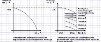
Mechanical characteristics of an asynchronous motor
The mechanical characteristic of an asynchronous motor is the dependence of the motor shaft speed on the torque on its shaft n
2=
f
(
M
) or
S
=
f
(
M
). Mechanical characteristics are shown in Fig. 13. Four characteristic points can be distinguished on the characteristic:
1 Ideal idle point. M in it
=0,
S
=0;
2 Point of nominal operating mode. In it M=MN
,
S=SN
.
The values of n
2
N
and
MN
can be determined from the engine catalog data;
3 Point of maximum or critical moment. In it M=Mm
,
S=SK
. This point characterizes the overload capacity of the engine.
| Rice. 13 |
In catalogs for determining the parameters of this point, the value of the critical engine torque multiplicity is given:
.
The magnitude of the multiplicity allows you to determine the maximum possible engine torque.
4. Start point. In it M=MP
,
S
=1. This point characterizes the starting properties of the engine. In catalogs for determining starting properties, the value of the engine starting torque multiplicity is given:
.
The catalogs also provide the starting current factor
which allows you to determine the value of the motor current at the moment of starting.
Synchronous machines
Synchronous machines as motors are usually used in high-power drives (more than 600 kW) or as micromotors, where strict constancy of speed is required: electric clocks, recorders, etc. The generator mode of operation of synchronous machines is most widespread, and almost all electrical energy is generated by synchronous generators, often called turbogenerators
. Synchronous generators for voltages up to 1000 V are used in units for autonomous power supply systems. Units with these generators can be stationary or mobile. Most units are used with diesel engines, but they can be driven by gas turbines, electric motors and gasoline engines.
The diagram of a synchronous machine is shown in Fig. 14. A synchronous machine differs from an asynchronous machine in that the current in the rotor winding does not appear when it rotates in the magnetic field of the stator, but is supplied to it from an external source of direct current. The stator of a synchronous machine is made in the same way as an asynchronous one, and a three-phase winding is usually located on it. The rotor winding in a synchronous machine creates a magnetic field flux and is called the field winding
.
The rotating rotor winding is connected to the external circuit of the DC source using slip rings and brushes. The armature winding
in a machine (generator) is the winding in which the emf is induced and to which the load is connected.
Rice. 14. Diagram of a synchronous machine:
B - excitation winding, Uв - voltage B of the excitation circuit
The resulting magnetic flux is created by the combined action of the field and stator windings and rotates at the same frequency as the rotor, which is why such machines are called synchronous.
In the diagram in Fig. 14, the stator is an armature, and the rotor is an inductor (exciter), but there can also be a reverse circuit, in which the stator is an inductor, and the rotor is an armature, like in a DC machine.
In a machine with a fixed armature, two types of rotor are used: salient pole rotor
has salient poles,
a non-salient pole rotor
does not have salient poles.
Rice. 15 . The principle of salient-pole (a) and non-salient-pole (b)
synchronous machine
/ - stator (armature), 2
- rotor (inductor), 3 - field winding
Direct current into the excitation winding of a synchronous machine can be supplied from a special direct current generator mounted on the machine shaft and called an exciter, or from the network through a semiconductor rectifier.
When the rotor rotates with a frequency n2, its magnetic excitation field induces an emf E1 in the stator, the frequency of which
f1
=p*n2/60
From the formula it follows that the greater the number of pole pairs of a synchronous machine p*,
the lower its rotation speed
n
to obtain a given frequency
fi.
Therefore, synchronous generators are usually produced salient-pole with a large number of pole pairs.
A synchronous motor is somewhat more complex than an asynchronous one; in addition, two types of current are required - alternating and direct. Such engines are usually produced with high power and have large dimensions. Synchronous motors have starting problems caused by the rotor entering synchronous mode when the motor starts. The following methods of starting a synchronous motor are possible: asynchronous starting at full mains voltage and starting at reduced voltage through an autotransformer. With asynchronous starting, at the moment of switching on (connecting the stator windings to a three-phase current system), the rotor windings are not connected to a direct current source, but are short-circuited. In this case, the engine becomes asynchronous in principle. After the rotor accelerates, its closed windings are opened and connected to a direct current source.
At the same time, a synchronous motor has a number of advantages, which makes it possible to use it in some cases instead of an asynchronous one.
1. The main advantage of a synchronous electric motor is the ability to obtain optimal reactive energy mode
, which is carried out by automatically regulating the motor excitation current. A synchronous motor can operate without consuming or supplying reactive energy to the network, with a power factor (cos phi) equal to unity. If an enterprise requires the generation of reactive energy, then a synchronous electric motor, working with overexcitation, can supply it to the network.
2. Synchronous electric motors are less sensitive to mains voltage fluctuations than asynchronous electric motors . Their maximum torque is proportional to the mains voltage, while the critical torque of an asynchronous motor is proportional to the square of the voltage.
3. Synchronous electric motors have a high overload capacity . In addition, the overload capacity of a synchronous motor can be automatically increased by increasing the excitation current, for example, with a sharp short-term increase in the load on the motor shaft.
4. The rotation speed of a synchronous motor remains unchanged at any load on the shaft within its overload capacity.
Mechanical characteristics of a synchronous electric motor.
Critical slide[edit | edit code]
If you gradually increase the engine load, the slip will increase (the rotor will lag further and further behind the rotating magnetic field), while the current induced in the rotor will increase in proportion to the slip, and the torque will increase in proportion to it. Therefore, at low loads we can assume that the moment is proportional to sliding. But as slip increases, active losses in the rotor increase, which reduce the rotor current, so the torque grows more slowly than the slip, and at a certain slip, the torque reaches a maximum and then begins to decrease. The sliding at which the moment reaches its maximum is called critical.