Agreed Mode
The matched mode is characterized by the fact that the power source supplies the receiver with the greatest amount of energy, which is possible with a certain relationship (matching) between the parameters of the circuit element.
The coordinated mode of any passive element of an external circuit is the mode in which this element operates with maximum power.
The matched mode of the source and the external circuit is the mode in which the greatest possible power is developed in the external circuit for a given source. The latter circumstance is often used, for example, in measuring circuits, when the matched mode makes the circuit more sensitive.
| Pros. the simplest direct current circuit with varying receiver resistance.| No-load modes ( a and short circuit ( b source. |
The matched mode of the source is the mode in which it delivers the greatest power to the external circuit. The latter circumstance is often used in special cases, which will be discussed later.
| O l i h i. h options for equivalent circuit electrical circuit 1 - 1. |
A matched mode between the source and the external circuit is a mode in which the resistance of the external circuit is equal to the internal resistance of the source. As will be shown later, in a matched mode, the greatest power possible with a given source develops in the external circuit. The latter circumstance is often used, for example, in measurement circuits, when the matched mode makes the circuit the most sensitive.
Violation of the agreed energy supply regime entails the application of civil liability measures to the energy supply organization.
In matched mode, the greatest power is released in the receiver (load). This mode is used in measuring circuits, in computing devices, information technology, and communications.
How is the condition for a matched two-terminal mode formulated?
In addition to measurements in an approximately matched mode at the ends of the line, the parameters of the linear path for the phase-phase connection circuit are additionally measured with an isolated and grounded non-working phase.
From an energy point of view, the matched mode is irrational, since only half of the power generated by the source reaches the receiver. The matched mode is used in some radio engineering devices, in automation and measurement technology, when energy considerations are not of decisive importance due to the small absolute value of the power.
From a technical and economic point of view, the matched mode is irrational, since only half of the power generated by the source reaches the receiver
The matched mode is used in some radio engineering devices, in automation and measurement technology, when it is important to obtain maximum receiver power. Energy considerations are not of decisive importance in this case due to the small absolute value of the power.
Both filters operate in a coordinated manner.
In the case when a coordinated mode is not ensured when directly connecting the generator and the consumer, matching devices are used.
6.12. Coordinated operating mode of the electrical circuit. Matching the load with the source
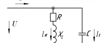
In the diagram in Fig. 6.20 - total, active and reactive resistance of the EMF source, - total, active and reactive resistance of the load. Active power can only be released in the active resistances of the alternating current circuit. The active power released in the load is
. (6.26)
Active power developed by the generator
. Efficiency for this circuit:
. Rice. 6.20
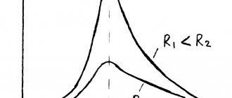
From formula (6.26) it is clear that the power released in the load will be maximum when the denominator is minimum. The latter occurs when , i.e. at . This means that the reactances of the source and load must be identical in magnitude and have a heterogeneous character. If the source reactance is inductive, the load reactance must be capacitive and vice versa.
. (6.27)
Let us establish the condition under which the greatest power will be transferred from the source to the load.
.
from here.
The greatest power is transferred from the source to the load when
. . (6.28)
Maximum power value
.
The mode of transfer of the greatest power from the source to the load is called the matched mode, and the selection of resistances according to equalities (6.28) is called matching the load with the source.
In a coordinated manner
.
Half the power is lost inside the source. Therefore, the matched mode is not used in power energy circuits. This mode is used in information circuits, where the power can be low, and the decisive factors are not considerations of the economy of signal transmission, but the maximum signal power in the load.
Operating modes of the electrical circuit
It is known that an electrical circuit is a collection of certain devices that provide a constant, continuous passage of electric current. The circuit cannot operate if any elements are missing; Both sources of energy and its conductors must be present, and receivers, as a rule, are the main devices that form this circuit. If we consider that in an electrical circuit there are various elements that are divided into three main groups: energy sources, current conductors and receivers, i.e., those elements that are powered by current and convert energy into its other types, then we can assume that there are also different operating modes of electrical circuits. Basic operating modes of electrical circuits As mentioned earlier, any electrical circuit can have a rather complex structure, depending on the number of elements in it and its branching. All this leads to the fact that the circuit can operate in different modes. There are three main operating modes: load (or matched), short circuit mode, and idle mode. They differ from each other in the load on the electrical circuit. You can also select the nominal operating mode. In this mode of operation, all devices in the circuit operate under the conditions specified for them as optimal. These characteristics are prescribed by the manufacturer in the passport data when the device is manufactured at the factory. Load, or coordinated operating mode. If any receiver is connected to an energy source in an electrical circuit, then it has a certain resistance. Such a receiver can be any device, for example, a light bulb. If there is voltage, then Ohm’s law applies, thus, the emf of the source is obtained from the sum of the voltages of the external section of the circuit and the internal resistance of the source. The voltage drop in the external circuit will be equal to the voltage at the source terminals. It depends on the load current: the lower the load resistance, the greater the current and, accordingly, the lower the voltage at the terminals of the circuit's power source. In other words, we can say that the load or matched operating mode is a mode in which a load of increased power is transferred from the source . In this mode, the load resistance is equal to the internal resistance of the source, and maximum power is consumed. However, this mode is not recommended, since if the nominal values are exceeded for a long time, the devices may fail. Idling mode. This mode of operation of the electrical circuit characterizes its open state - there is no current, and all elements are disconnected from the power source. In this state of the circuit, the internal voltage drop is zero, and the voltage at the terminals of the power source coincides with the emf of the source.T. That is, we can say that the idle mode characterizes the electrical circuit when it is in an open state and the load resistance is completely absent or disconnected. This state of the circuit can be used to measure the EMF of the power source. Short circuit mode. This operating mode is considered an emergency; the electrical circuit cannot operate normally. A short circuit occurs when two different points in a circuit are connected, the potential difference of which is different. This condition is not provided for by the manufacturer of the device and disrupts its normal operation. In this operating mode, the terminals of the energy source are closed by a conductor (“shorted”), and its resistance is close to zero. Often, a short circuit occurs in cases where two wires are connected that connect the source and receiver in the circuit; as a rule, their resistance is insignificant, so it can be called zero. When a short circuit occurs, the current in the circuit significantly exceeds the rated one values (due to lack of resistance). This can render the power source and receivers in the electrical circuit unusable. In some cases, this is the result of improper actions on the part of personnel working with electrical equipment.
Electrical Circuit Basics
Just as water flows through a plumbing system (through pipes, faucets, filters, meters, etc.), electricity flows through a circuit (wires, electrical and electronic components, through plugs and sockets, etc.). Electricity is one of several types of energy that, as it flows, can release light, heat, sound, radio waves, mechanical motion, electromagnetic fields, etc. Take any electrical equipment (computer, mobile phone, electric oven, TV, etc.), it all contains electrical circuits consisting of various electrical circuits through which current flows, and on which there is a voltage of a certain magnitude and polarity.
Let's take a closer look at what an electrical circuit is and exactly how current flows through it. So, electric current is the ordered movement of electrically charged particles. Let me remind you that in solids the carriers of electric charge are electrons (particles with a negative charge, also known as minus). In liquids and gases, the carriers of electric charge are ions (atoms and molecules that have a lack of electrons in their orbits and have a positive charge, also known as a plus). Most often we have to deal with the movement of electrons along an electrical circuit in solid conductors (these are metals, crystals).
Complex electrical circuit
An electrical circuit is a closed path through which current flows and electrically charged particles run. The movement of these particles itself can be represented as follows. As you should know from your physics lessons, all substances consist of atoms and molecules (the smallest particle of the substance itself, its structural component). In solid states of matter, atoms are arranged in a certain order and have a so-called crystal lattice. In some substances, the electrons that are furthest from the center of the atom can easily break away from their atom and move to the neighboring one. This results in the movement of charged particles within the substance itself.
Such substances are conductors of electric current. Some do it well, others do it worse (conduct current). If we take a substance such as copper (metal), which conducts electricity quite well through itself, and make a wire out of it, then in the end we will get a conductor of electric current of a certain length.
We also need a current source, which, depending on its principle of operation, can create an excess of negative charge at one pole, and a positive charge at the other (also known as a lack of negative charge).
For current to flow, a bridge is needed, as it were, connecting these very opposite poles. The role of this bridge, for the transfer of electric charge from one pole to another, will be a closed electrical circuit consisting of various conductors.
An electrical circuit is a collection of devices and objects that form a path for electric current, the electromagnetic processes in which can be described using the concepts of electromotive force, current and voltage. In a direct current electrical circuit, both constant currents and currents can act, the direction of which remains constant, but the value changes arbitrarily over time or according to some law.
For example, we will simply connect the poles of the power source with ordinary copper wire. As a result, current will flow through the wire (that same excess of electrical charges). This will be, perhaps, the simplest electrical circuit that can only create a short circuit of this very power source. But it is still an electrical circuit. A more useful electrical circuit would be the following circuit - a power source (a regular battery), wires, a switch and a light bulb (calculated for the voltage of the power source). When we connect all this one after another (in series) we will already get an electrical circuit where the flow of current will bring benefits in the form of light emission from an electric bulb.
Naturally, electrical engineering is not limited to such simple electrical circuits. If you correctly connect various electrical and electronic components to each other, connecting a power source to them, creating various functional circuits, you can ultimately get all the variety of electrical devices that we now have. And they all have electrical circuits of varying complexity.
Interesting on the topic: How to check a zener diode.
An electrical circuit is a collection of devices and objects that form a path for electric current, the electromagnetic processes in which can be described using the concepts of electromotive force, current and voltage. In a direct current electrical circuit, both constant currents and currents can act, the direction of which remains constant, but the value changes arbitrarily over time or according to some law. An electrical circuit consists of individual devices or elements, which, according to their purpose, can be divided into 3 groups.
It will be interesting➡ How a three-phase rectifier works
The first group consists of elements intended for generating electricity. These are called power supplies.
The second group is elements that convert electricity into other types of energy (mechanical, thermal, light, chemical, etc.). These elements are called electrical energy receivers (electrical receivers).
The third group includes elements designed to transmit electricity from a power source to an electrical receiver (wires, devices that ensure the level and quality of voltage, etc.).
Related material: How to connect a capacitor
DC circuit power sources are galvanic cells, electric batteries, electromechanical generators, thermoelectric generators, photocells, etc. All power sources have internal resistance, the value of which is small compared to the resistance of other elements of the electrical circuit.
DC power receivers are electric motors that convert electrical energy into mechanical energy, heating and lighting devices, etc. All power receivers are characterized by electrical parameters, among which the most basic are voltage and power.
For normal operation of the electrical receiver, it is necessary to maintain the rated voltage at its terminals. For DC receivers it is 27, 110, 220, 440 V, as well as 6, 12, 24, 36 V.
Electric circuit and its elements.
A graphical representation of an electrical circuit containing symbols of its elements and showing the connections of these elements is called an electrical circuit diagram. The elements of an electrical circuit are various electrical devices that can operate in different modes.
The operating modes of both individual elements and the entire electrical circuit are characterized by current and voltage values. Since current and voltage can generally take on any values, there can be an infinite number of modes.
Idle mode is a mode in which there is no current in the circuit. This situation can occur when the circuit breaks. The nominal mode occurs when the power source or any other circuit element operates at the values of current, voltage and power specified in the passport of this electrical device.
These values correspond to the most optimal operating conditions of the device in terms of efficiency, reliability, durability, etc. Short circuit mode is a mode when the receiver resistance is zero, which corresponds to the connection of the positive and negative terminals of the power source with zero resistance.
The short circuit current can reach large values, many times higher than the rated current. Therefore, short circuit mode is an emergency for most electrical installations.
Matched mode between the power supply and the external circuit occurs when the resistance of the external circuit is equal to the internal resistance.
In this case, the current in the circuit is 2 times less than the short circuit current. The most common and simplest types of connections in an electrical circuit are series and parallel connections.
Series connection of circuit elements
In this case, all elements are connected to the circuit one after another. A serial connection does not make it possible to obtain a branched circuit - it will be unbranched. In Fig. Figure 1 shows an example of a series connection of elements in a circuit.
In our example, two resistors are taken. Resistors 1 and 2 have resistances R1 and R2. Since the electric charge does not accumulate in this case (direct current), then for any cross-section of the conductor, the same charge passes through a certain time interval. It follows from this that the current strength in both resistors is equal:
I = I1 = I2
But the voltage at their ends is summed up:
U = U1 + U2
According to Ohm's law, for the entire section of the circuit and for each resistor separately, the total resistance of the circuit will be:
R = R1 + R2
In the case of a series connection of conductors, voltage and resistance can be expressed by the relationship:
U1/U2 = R1/R2
Opening three-phase current.
Parallel connection of conductors
When two conductors are connected in parallel, the electrical circuit has two branches. The branching points of conductors are called nodes. Electric charge does not accumulate in them, i.e., the electric charge entering the node over a certain period of time is equal to the charge leaving the node during the same time. It follows that:
It will be interesting➡ Direct current - definition and parameters
I = I1 + I2
where I is the current strength in an unbranched circuit.
When connecting conductors in parallel, the voltage on them will be the same. Let us denote the resistance of two conductors connected in parallel as R1 and R2. Using Ohm's law for sections of an electrical circuit with given resistances, it can be revealed that the reciprocal of the total resistance of the section ab is equal to the sum of the reciprocals of the resistances of individual conductors, i.e.:
1/R = 1/R1 + 1/R2
From this it follows:
R = R1R2/(R1 + R2)
This formula is valid only for determining the total resistance of two conductors connected in parallel. The reciprocal of resistance is called conductivity. When conductors are connected in parallel, their resistance and current are related by the relationship:
I1/I2 = R2/R1
Capacitor connections
There are also two types of connection for capacitors: series and parallel.
Serial connection . In this case, the plate of one capacitor, charged negatively, is connected to the plate of another capacitor, charged positively. In Fig. Figure 3 shows an example of a series connection of capacitors.
With this type of connection, the following rule applies: the reciprocal of the capacitance of a bank of capacitors in a series connection is equal to the sum of the reciprocals of the capacitances of individual capacitors. Therefore:
1/С = 1/С1 + 1/С2 + 1/С3 + …
With this type of connection, the capacitance of the capacitor bank is less than the capacitance of any of the capacitors.
Parallel connection . When capacitors are connected in parallel, positively charged plates are connected to positively charged ones, and negatively charged plates are connected to negative ones (Fig. 4).
In this case, the capacitance of the capacitor bank will be equal to the sum of the electrical capacitances of the capacitors:
C = C1 + C2 + C3 + ...
Power supply connections
With the parallel method of connecting current sources, all positive and all negative poles are connected to each other. The voltage on an open battery will be equal to the voltage on each individual source, i.e., with a parallel connection method, the emf of the battery is equal to the emf of one source. The battery resistance when the sources are connected in parallel will be less than the resistance of one element, because in this case their conductivities are summed up.
When connecting current sources in series, two adjacent sources are connected to each other by opposite poles. The potential difference between the positive pole of the last source and the negative pole of the first will be equal to the sum of the potential differences between the poles of each source.
It follows from this that when connected in series, the emf of the battery is equal to the sum of the emf of the sources included in the battery. The total resistance of the battery when the sources are connected in series is equal to the sum of the internal resistances of the individual elements.
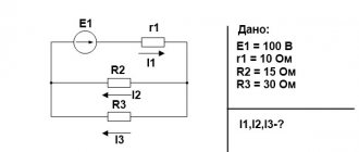
Calculation of electrical circuits
The basis for calculating electrical circuits is determining the strength of currents in individual sections at a given voltage and pre-known resistance of individual conductors. Let's say we know the total voltage at the ends of the circuit. The resistances R1, R2 ... R6 of the resistors R1, R2, R3, R4, R5, R6 connected to the circuit are also known (the resistance of the ammeter is not taken into account). It is necessary to calculate the current strength I1, I2, ... I6.
First of all, you need to clarify how many consecutive sections this chain has. Based on the proposed scheme, it is clear that there are three such sections, with the second and third containing branches. Let us assume that the resistances of these sections are R1, R', R”. This means that the entire resistance of the circuit can be expressed as the sum of the resistances of the sections:
R = R1 + R' + R”
where R' is the total resistance of parallel-connected resistors R2, R3 and R4, and R” is the total resistance of parallel-connected resistors R5 and R6. By applying the law of parallel connection, we can calculate the resistances R' and R”:
1/R' = 1/R2 + 1/R3 + 1/R4 and 1/R” = 1/R5 + 1/R6
In order to determine the current in an unbranched circuit using Ohm's law, you need to know the total resistance of the circuit at a given voltage. To do this, use the formula:
I = U/R
From the above it can be concluded that I = I1.
But to determine the current strength in individual branches, you must first calculate the voltage in individual sections of the serial circuits. Again, using Ohm's law, we can write:
U1 = IR1; U2 = IR'; U3 = IR”
Now, knowing the voltage in individual sections, you can determine the current strength in individual branches:
I2 = U2/R2; I3 = U2/R3; I4 = U2/R4; I5 = U3/R5; I6 = U3/R6
There are times when you need to calculate the resistance of individual sections of a circuit based on already known voltages, currents and resistance of other sections, as well as determine the required voltage based on given resistances and currents. The method for calculating electrical circuits is always the same and is based on Ohm's law.
Electric circuit
6.10. Power in a sinusoidal current circuit
Instantaneous power is the product of the instantaneous voltage at the input of the circuit and the instantaneous current. Let the instantaneous voltage and current be determined by the formulas:
Then
(6.23)
Average value of instantaneous power for the period
From the resistance triangle, a.
We get another formula:
.
The arithmetic average value of power over a period is called active power and is designated by the letter P. This power is measured in watts and characterizes the irreversible conversion of electrical energy into another type of energy, for example, into thermal, light and mechanical energy. Let's take a reactive element (inductance or capacitance). Active power in this element, since the voltage and current in the inductance or capacitance differ in phase by 90o. There are no irreversible losses of electrical energy in reactive elements, and the elements do not heat up. A reversible process occurs in the form of an exchange of electrical energy between the source and the receiver. To qualitatively assess the intensity of energy exchange, the concept of reactive power Q is introduced. Let us transform the expression:
where is the instantaneous power in the active resistance;
- instantaneous power in a reactive element (in inductance or capacitance).
The maximum or peak value of power p2 is called reactive power
,
where x is reactance (inductive or capacitive). Reactive power, measured in reactive volt-amperes, is spent on creating a magnetic field in an inductance or an electric field in a capacitance. The energy stored in a capacitance or inductance is periodically returned to the power source. The amplitude value of the total power p = p1 + p2 is called the total power. The total power, measured in volt-amperes, is equal to the product of the effective values of voltage and current:
,
where z is the total resistance of the circuit.
Total power characterizes the maximum capabilities of the energy source. Part of the total power can be used in an electrical circuit
,
where is the power factor or cosine phi.
Power factor is one of the most important characteristics of electrical devices. Special measures are taken to increase the power factor. Let's take a resistance triangle and multiply its sides by the square of the current in the circuit. We obtain a similar power triangle (Fig. 6.18).
From the power triangle we obtain a number of formulas:
, ,
Fig.6.18, .
When analyzing electrical circuits using the symbolic method, the complex power expression is used, which is equal to the product of the complex voltage and the conjugate complex current. For a circuit that is inductive in nature (RL circuit)
,
where is the stress complex;
— current complex;
— conjugate current complex; - phase shift between voltage and current. , the current is the same as in an RL circuit, the voltage is ahead of the current in phase.
The real part of the total complex power is the active power. The imaginary part of complex power is reactive power. For a circuit that has a capacitive nature (R-C circuits), . The current is ahead of the voltage in phase.
.
Active power is always positive. Reactive power in an inductive circuit is positive, and in a capacitive circuit it is negative.
Electrical circuit composition
The electrical circuit includes (in the general case): power source, switch (switch), connecting wires, consumers. Be sure to form a closed loop. Otherwise, no current will be able to flow through the circuit. It is not customary to call grounding and grounding circuits electrical. However, they are essentially considered as such; sometimes current flows here. Closing the circuit when grounding or zeroing is ensured through the ground.
It will be interesting➡ How a voltage rectifier works
Power supplies. Internal, external electrical circuit
To form an ordered movement of charge carriers that forms a current, take the trouble to create a potential difference at the ends of the section. This is achieved by connecting a power source, which in physics is usually called an internal electrical circuit. In contrast to other elements that make up the external. In a power source, charges move against the direction of the field. Achieved by the application of third-party forces:
- Generator winding.
- Galvanic power source (battery).
- Transformer output.
The voltage generated at the ends of a section of an electrical circuit can be alternating or constant. According to technology, it is customary to divide the contours accordingly. An electrical circuit is designed for the flow of direct and alternating current. A simplified understanding, the law of change in the ordered movement of charge carriers, is perceived as complex. It is difficult to understand whether the current in the circuit is alternating or direct.
Electrical circuit design
The type of current is determined by the source, the nature of the external electrical circuit. The galvanic element provides constant voltage, the windings (transformers, generators) provide alternating voltage. Associated with processes occurring in the power source. Third-party forces that ensure the movement of charges are called electromotive. Numerically, the EMF is characterized by the work performed by the generator to move a unit charge. Measured in volts. In practice, to calculate circuits, it is convenient to divide power supplies into two classes:
- Voltage sources (EMF).
- Current sources.
In reality unknown, practitioners are trying to create an imitation. We expect to see 230 volts in the outlet (220 volts according to old standards). Moreover, GOST 13109 clearly establishes the limits of deviation of parameters from the norm. In everyday life we use a voltage source. The parameter is normalized. The amount of current does not matter. They strive to keep the substation voltage constant around the clock, regardless of the current consumer demand.
In contrast, the current source maintains a given law of ordered movement of charge carriers. The voltage value does not matter. A striking example of this type of device is an inverter-based welding machine. Everyone knows: the diameter of the electrode is closely related to the thickness of the metal and other factors. In order for the welding process to proceed correctly, the current must be maintained with a high degree of consistency.
The problem is solved by an electronic unit based on an inverter. Current and voltage can be constant or variable. The law of parameter change does not play a role. It does not matter whether the electrical circuit is connected to a DC or AC voltage source. However, it is important to maintain the correct parameter size. For example, the effective value of the emf.
Switch
The switch will allow you to connect the power source to the wires of the consumer. Everyone (with a few exceptions) used a wall switch. When an electrical circuit closes or opens, a spark occurs. This is explained by the presence of capacitive resistance. To prevent sparking, the circuit is supplemented with a choke, the switch is formed by special type contactors. Other technical solutions have been invented, for example, the Tesla coil.
Wires
In technology, wires are made of copper and aluminum. Associated with low resistivity of metals. The price is low. The heat generated on the conductors is determined by two parameters:
- Circuit section resistance.
- Electricity.
It is clear that the second parameter is determined by the needs of consumers. The supplier seeks to influence the former. The resistivity of the conductor is expected to be as low as possible. Scientists have long been interested in the phenomenon of superconductivity. Metals lose resistance when the temperature drops. Losses are reduced. Among semiconductors, there are samples with positive and negative temperature coefficients of resistance. The absolute value of the parameter for metals is orders of magnitude lower.
The problem with aluminum and copper is simple: when electric current flows in the circuit, the temperature rises. The resistance of the area increases, further aggravating the situation. It turns out to be a vicious circle. Scientists believe that the problem can be corrected by enlisting the help of the phenomenon of superconductivity.
At a certain low temperature, a metal sharply, jerkily reduces resistance, reaching zero (above the threshold the graph decreases smoothly at a speed of 1/273 1/deg). The problem in practical application is that the values that trigger the jump are low. For example, for lead the limit is 7.2 K. Extremely low negative temperature on the Celsius scale.
Scientists see a solution to the problem in the discovery of materials that demonstrate the phenomenon of superconductivity at room temperatures. Then large currents can be transferred to consumers, avoiding losses. In an electrical circuit formed by superconductors, charges can circulate indefinitely without external recharge from a source.