Topic 1.2. DC electrical circuits
Electrical circuits and its elements
A direct current electrical circuit is a set of devices and objects: sources of electrical energy, converters, consumers, switching, protective and measuring equipment, connecting wires or power lines.
Electrical and electromagnetic processes in these objects are described using the concepts of electromotive force (EMF - E), current (I) and voltage (U).
Circuit elements can be divided into three groups:
1) elements intended for generating electricity (energy sources, EMF sources);
2) elements that convert electricity into other types of energy: mechanical, thermal, light, chemical, etc. (these elements are called electrical energy receivers or consumers);
3) elements designed to transmit electrical energy from a source to receivers (power lines, connecting wires); elements that ensure the level and quality of voltage, etc.
DC circuit power sources are galvanic cells, electric batteries, electromechanical generators, thermal and photoelements, etc.
Electrical receivers or consumers of direct current are electric motors that convert electrical energy into mechanical energy, heating and lighting devices, electrolysis installations, etc. All electrical receivers are characterized by electrical parameters, among which the main ones are voltage and power. For normal operation of the electrical receiver, it is necessary to maintain the rated voltage at its terminals. According to GOST 721-77, the voltage is 27, 110, 220, 440 V, also 6, 12, 24, 36 V.
Switching equipment is used to connect consumers to sources, that is, to close and open electrical circuit sources.
The protective equipment is designed to open the circuit in emergency situations.
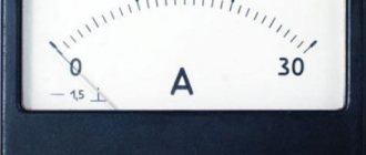
Measuring equipment is designed to measure current, voltage and other electrical quantities.
Power lines are used when sources and consumers are located long distances from each other. Connecting wires are designed to connect clamps or electrodes of electrical circuit elements to each other.
Active and passive elements
An element is called passive if it cannot cause current to flow, that is, if it does not create current or emf. If you assemble several passive elements (resistors, capacitors, inductors) into an electrical circuit, then no current will flow in the circuit.
The element that creates EMF and causes current to flow is called active (electricity sources).
Linear and nonlinear circuits
An electrical circuit is called linear if the electrical resistance or other parameters of the sections do not depend on the values and directions of currents and voltages. Electrical processes in a linear circuit are described by linear algebraic and differential equations.
If an electrical circuit contains at least one nonlinear element, then it is nonlinear.
Topological elements of an electrical circuit.
A graphical representation of an electrical circuit is called an electrical diagram. The electrical circuit includes: nodes, branches, circuits.
A branch is a collection of elements connected in series. The same current flows through the branch.
A node is a point at which three or more branches connect.
A circuit is a set of branches that, when traversed, create a closed path.
The simplest electrical circuit has one circuit with one branch and has no nodes. Complex electrical circuits have several circuits.
Positive directions of current, voltage and emf.
In order to correctly write equations describing processes in electrical circuits and analyze these processes, it is necessary to set the conditional positive directions of the EMF of power sources, the current in the elements or branches of the circuit and the voltage at the terminals of the circuit elements or between the nodes of the circuit.
Inside a DC emf source, the positive direction of the emf is from the negative pole to the positive pole. This corresponds to the definition of EMF as a quantity characterizing the ability of external forces to cause electric current.
With respect to the EMF source, all circuit elements constitute the outer section of the circuit.
The positive direction of the current in the circuit is taken to be the direction coinciding with the direction of the emf. In an external circuit, the positive direction is from the positive pole of the source to the negative pole. In electronic theory, the direction coincides with the direction of positively charged particles.
The conditional positive direction of the voltage drop (or simply voltage) on the elements of a circuit or between two nodes of a circuit is taken to be the direction that coincides with the conditionally positive direction of the current in this element or in this branch. The positive direction of voltage at the terminals of the EMF source is always opposite to the positive direction of the EMF.
The actual directions of electrical quantities determined by calculation may or may not coincide with the conditional directions. In calculations, if it is determined that the current, emf and voltage are positive, then their actual directions coincide with the conventionally accepted positive directions; if they are negative, then they do not coincide.
Basic laws of electrical circuits
Symbol of parameters in DC and AC circuits.
i – alternating current; I – direct current;
u – alternating voltage; U – constant voltage;
e – variable EMF; E – constant EMF;
Source
Basic formulas of electricity
Studying the fundamentals of electrodynamics and electrics is impossible without determining the electric field, precise charges, resistance and other phenomena.
Electricity formulas
Therefore, it is important to consider all the basic formulas of electricity and examples of solving problems using them.
Coulomb's law
According to a short description, this is a physical law that talks about the interaction between directly standing point electric charges, depending on the distance at which they are located. According to the full definition, the formulation means that a vacuum is formed between two points in the form of electric charges. A specific force appears there, which is proportional to the multiplication of their modular particles divided by the square of the distance.
Distance is the length that connects charges. The interaction force is directed along the segment. Coulomb force is a force that is repulsive for charges minus-minus and plus-plus and attractive for charges minus-plus and plus-minus.
Note! The electric force formula looks like this: F=k⋅|q1|⋅|q2|/r2, where F is the force of the charge, q is the magnitude of the charge, r is the vector or distance between charges, and k is the proportionality coefficient. The latter is equal to c2·10−7 H/m.
Coulomb's law
Solving the problem with Coulomb's law. If you have charged balls that are located at a distance of 15 cm and repel with a force of 1 N in search of the initial charge, you can identify the unknown by converting the base units to the SI system and substituting the values into the indicated formula. The value will be 2 * 5 * 10 (-8) = 10 (-7).
Field strength of a solitary point charge
The electric field, being matter created by electric point charges, is characterized by different quantities, including intensity. Tension acts as a vector quantity or force characteristic of the field, which is directed towards the electrostatic interaction of charges. To obtain it, you need to use the formula E = k (q / r (2)), where E is a vector field.
Field strength of a solitary point charge
According to this formulation, the charge field strength is inversely proportional to the square value of the distance from the charge. That is, if the gap increases several times, the voltage indicator decreases by four.
You can apply the law to solve problems. For example, the radius is unknown. Then you need to convert the constant. You need to solve the equation E / r (2) = kq by substituting known numbers.
Potential of a point in the field of a point charge
Potential in an electrostatic field is a scalar quantity that is equal to dividing the potential charge energy indicator by it. It does not depend on the value of q that is placed in the region. Since the potential energy indicator depends on which coordinate system is chosen, the potential is determined accurate to a constant. It is equal to the work field that displaces a unit positive charge to infinity. Expressed through φ = W / q =const.
You might be interested in How a capacitor is charged
Potential of a point in the field of a point charge
Note! In tasks, you can convert a constant. If W is unknown, then we can divide q by φ, and if q, then W by φ.
Potential charge energy in an electrostatic field
Potential energy of a charge in an electrostatic field
Since the work of an electric field does not depend on the chosen motion of the charged particle, but on its initial and final position, there is the term potential energy. This is a scalar quantity in a space coordinate that shows how the force works when a particle moves along an arbitrary interval from one point to another. It is equal to the difference in the values of particle movement in this interval. It is expressed in the following form: A = P1 - P2, where P1 can be x, y and z, and P2 can be x2, y2 and z2. In physics problems, you need to draw a graph, substitute known values into a constant, and solve equations.
Potential energy of charge q1 in the field of a point charge
When charged particles move across a field from one point to another, they perform some work over a certain time period. The potential energy at these points does not depend on which path the charged particles take. The energy of the first charge is proportional to its modulus. This is all expressed in the formula presented in the picture below. Problems can be solved by using the presented constant and inserting known values.
Potential energy of charge q1 in the field of a point charge
Gauss's theorem
The fundamental law in electrodynamics, included in Maxwell's equations. This is a consequence of the Coulomb inference and the principle of superposition. Along it, the field voltage vector moves through an arbitrary value of a closed surface surrounded by charges. It is proportional to the sum of charged particles that are inside this closed space. The specified vector is divided by e0. All this is expressed by the formula below.
Gauss's theorem
Electric field strength near the surface of the conductor
The intensity of the total space of charged particles is directly proportional to the surface indicator of their density. If the problem requires finding the tension, and the surface charged density is sigma, then you need to draw a cylinder and designate that the flux through its side surface is 0. In this case, the tension lines will be parallel to the side surface. It turns out that φ = 2φ, main = 2еs, and 2es = q / 2ε0.
Electric field strength near the surface of the conductor
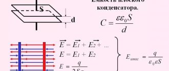
Capacitance of parallel plate capacitor
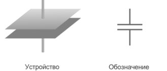
Capacitance is a conductive characteristic through which an electric charge can accumulate energy. A flat capacitor is a series of oppositely charged plates separated by a thin dielectric layer. The capacitance of a flat capacitor is considered to be its characteristic, its ability to accumulate electrical energy.
Note! This is a physical quantity that is equal to the charge divided by the potential difference of its plate. The charge in this case is one charged plate.
If the problem requires finding out the capacitance of a capacitor made of two plates with an area of 10(-2) square meters and there is a 2*10(-3) meter sheet in them, ε0 is the electric constant with 8.85×10⁻¹² farads per meter and ε =6 is the dielectric constant of mica. In this case, you need to insert the values into the formula C= ε* ε* S/d.
Capacitance of parallel plate capacitor
Energy of a parallel plate capacitor
Since any particle of a capacitor has the ability to store energy, which is stored on the capacitor plate, calculating this very E is simple, since in order for the element to charge, it needs to do work. The work is done by the field. As a result, the following formula was derived: Ep = A = qEd, where A is the work, d is the distance.
Energy
Methods for calculating electrical circuits
To correctly calculate the electrical circuit and its parameters on different parts, special methods are used, such as:
- circuit conversion method;
- overlay method;
- loop current method;
- equivalent generator method;
- nodal potential method;
- method of applying Kirchhoff's laws.
The loop current method is based on the use of additional values of loop currents corresponding to Kirchhoff's law.
The equivalent generator method is used to calculate the currents of one or more branches. This method is also called the active two-terminal theorem.
The method of nodal potentials makes it possible to reduce the order of the system of equations. It consists in determining the potentials of all nodes of the circuit based on the given potentials of the currents of all branches. This method is based on Kirchhoff's first law.
The most commonly used methods for calculating circuit parameters are the method of applying Kirchhoff's laws and the method of circuit transformation. Let's take a closer look at them.
Electrical circuit conversion method
This method consists of correctly calculating the distribution of currents in the circuit. Resistors connected in series or parallel are replaced by one resistance, as a result of which the current distribution does not change.
In the case of a series connection of resistances, they will be connected so that the end of the previous one will be connected to the beginning of the next one. With this connection, the current will have the same value in each resistor.
In any electrical circuit there are sources and receivers of electricity that are connected by wires. This connection makes it possible for current to flow through wires from one element to another. The sources are voltage and current sources.
An ideal voltage source is considered to be one whose terminal voltage does not change over time, regardless of the current it supplies to the load, and its internal resistance is equal to zero.
An ideal current source is considered to be one that produces a constant current value over time, independent of the voltage at the terminals, and its internal resistance is equated to an infinitely large value.
Source
D.C
Electric current is the ordered movement of charged particles (electrons and ions). The direction of current is conventionally taken to be the direction of movement of positive charges, i.e. from "+" to "-".
Conditions necessary for the existence of electric current:
- The presence of free charged particles;
- The presence of an electric field acting on charged particles with a force in a certain direction;
- The presence of a closed electrical circuit.
Actions of current:
- Thermal: the conductor through which current flows heats up.
- Chemical: Electric current can change the chemical composition of the conductor (electrolyte).
- Magnetic: the current exerts a force on neighboring currents and magnetized bodies. There is a magnetic field around a conductor carrying current.
Electromotive force.
If two charged bodies are connected by a conductor, then a short-term current will flow through it. Excess electrons from a negatively charged body will move to a positively charged one. The potentials of the bodies will be the same, which means that the voltage at the ends of the conductor will become zero and the current will stop. For a long current to exist in a conductor, the potential difference at its ends must be maintained constant. This can be achieved by transferring free electrons from a positive body to a negative body so that the charges of the bodies do not change over time.
The forces of electrical interaction by themselves are not capable of carrying out such a separation of charges. They cause electrons to be attracted to the positive body and repelled from the negative body. Therefore, external forces must act inside the current source, having a non-electrical nature and ensuring the separation of electrical charges.
Third-party forces are any forces acting on electrically charged particles, with the exception of forces of electrostatic origin (i.e. Coulomb).
EMF - electromotive force - a physical quantity determined by the work done by external forces when moving a single positive charge from the “+” pole to the “-” pole inside the current source. It is an energy characteristic of a current source.
Basic characteristics of electric current
Types of current source connections
Ammeter shunting.
An important example of the use of serial and parallel connection of wires are various circuits for connecting electrical measuring instruments. Let us assume that there is a certain ammeter designed for the maximum current Imax, but it is required to measure a large current. In this case, a small resistance r is connected in parallel to the ammeter, through which most of the current will be directed. It is usually called a shunt. The resistance of the ammeter is R, and let R/r=n. The current strength in the circuit, ammeter and shunt is equal to I, Ia and Ish, respectively
Connecting a shunt in parallel to a measuring device in order to change its sensitivity is called shunting . Circuit for shunting an ammeter with an additional small resistance r.
D.C. Work and power. Joule-Lenz law.
The work done by the electric field to move charge ∆ q from one point to another is equal to the product of the voltage U between these points and the amount of charge Dq: A=DqU
DISTRIBUTION OF POTENTIALS AND CURRENT IN AN ELECTRICAL CIRCUIT
In order to understand the passage of current through electrical circuits, one must imagine how electrical potentials are distributed in it. Electric current always passes from points in the circuit that are at high potential to points that are at lower potential. If any point in the circuit is connected to ground, then its potential is assumed to be zero; in this case, the potentials of other points in the circuit will be equal to the voltages acting between these points and the ground.
Let's look at this issue using a few specific examples.
In Fig. 27, a
shows the distribution of potentials in a series electrical circuit under voltage, provided that
r1 = r2 = r3.
Point
A
has the highest positive potential φA, since it is connected to the positive pole of the source (the source itself is not shown in the diagram - only the wires of the network connecting it to points
A
and
D are shown).
The potential
φB
at point
B
will be less than at point
A,
therefore, in section
A B
the current flows from point
A
to point
B.
The potential difference between points
A
and
B
is equal to the voltage drop
U1 = Ir1 in a resistor with resistance r1.
This voltage drop increases gradually as we move from point
A
to point
B,
so along the resistor with resistance r
1
the potential also decreases gradually.
At point B
the potential is zero.
The potential difference between points B
and
C
is equal to the voltage drop U2
= Ir2 in
a resistor
.
Point
G
will have a negative potential with respect to point
B
(it is connected to the negative pole of the source), so current I flows from point B
to
point G.
It should If you ground two or more points in a circuit that have different potentials, then additional current-carrying branches are formed through the ground and the current distribution in the circuit changes.
Series and parallel connection of conductors
Series and parallel connection of conductors are the main types of conductor connections encountered in practice. Since electrical circuits, as a rule, do not consist of homogeneous conductors of the same cross-section. How to find the resistance of a circuit if the resistances of its individual parts are known.Let's consider two typical cases. The first of these is when two or more resistive conductors are connected in series. In series means that the end of the first conductor is connected to the beginning of the second, and so on. With this connection of the conductors, the current strength in each of them will be the same. But the voltage on each of them will be different.
Figure 1 - serial connection of conductors
The voltage drop across the resistances can be determined based on Ohm's law.
Formula 1 - Voltage drop across resistance
The sum of these voltages will be equal to the total voltage applied to the circuit. The voltage on the conductors will be distributed in proportion to their resistance. That is, you can write it down.
Formula 2 - the relationship between resistance and voltage
The total resistance of the circuit will be equal to the sum of all resistances connected in series.
Formula 3 - calculation of the total resistance when connected in parallel
The second case is when the resistances in the circuit are connected in parallel to each other. That is, there are two nodes in the circuit and all conductors with resistance are connected to these nodes. In such a circuit, the currents in all branches are generally not equal to each other. But the sum of all currents in the circuit after the branching will be equal to the current before the branching.
Figure 2 - Parallel connection of conductors
Formula 4 - relationship between currents in parallel branches
The current strength in each of the branched circuits also obeys Ohm's law. The voltage on all conductors will be the same. But the current strength will be separated. In a circuit consisting of parallel-connected conductors, the currents are distributed in proportion to the resistances.
Formula 5 - Distribution of currents in parallel branches
To find the total resistance of the circuit in this case, it is necessary to add the reciprocal values of the resistances, that is, the conductivity.
Formula 6 - Resistance of parallel-connected conductors
There is also a simplified formula for the special case when two identical resistances are connected in parallel.
Formula 7 - resistance of two identical conductors
When resistors are connected in parallel, they say that the total resistance is less than the smallest. In general, a circuit can consist of mixed-connected conductors. Then it is divided into sections where they are connected either in parallel or in series and a calculation is made.
Figure 3 - mixed connection of conductors
If the circuit cannot be divided into elementary sections, the currents in it are calculated using Kirgkoff's laws.
Figure 4 - circuit calculated using Kirgkoff rules
DC Circuit Diagrams
When calculating electrical circuits, in most cases the parameters of the emf or voltage sources and the resistance of the elements of the electrical circuit are known, and the task comes down to determining the currents in the branches of the circuit. Thus, the electrical circuit in Fig.
Point H determines the rated mode if the voltage and current correspond to their nominal values Unom and Inom given in the passport of the electrical energy source.
An element of an electrical circuit, the parameters of which are resistance, etc. Electrical circuits (part 1)
Elements of a circuit An electrical circuit contains components such as energy sources, consumers, and the wires connecting them. According to Ohm's law, the currents in each branch are: According to Kirchhoff's first law, the total current Mixed connection is a combination of the first two connections, where a parallel connection can be converted to a series connection.
To compile them, it is necessary to specify the conditional directions of the currents in the branches; we will enter the number in accordance with the serial number of the resistances.
Method of nodal potentials The second method used to solve complex circuits is the method of nodal potentials. Then from expression 1.
External current-voltage characteristic of the electrical energy source Point X of the current-voltage characteristic of the electrical energy source corresponds to idle mode x.
Connecting a circuit to a source of constant EMF 5. There are additional circuit devices, for example, switches, current meters and protective devices. CAPACITOR IN DC AND ALTERNATING CURRENT CIRCUIT [Radio Amateur TV 89]
Calculation of circuits using the equivalent transformation method
When calculating DC electrical circuits, as a rule, the parameters of electrical energy sources and the parameters of other electrical energy elements are known. The task comes down to determining the currents in all branches of the circuit and the voltages on all its elements.
When calculating electrical circuits, it often becomes possible to transform the diagrams of these circuits into simpler and more convenient ones for calculation. One of the most commonly used equivalent transformation methods in practice is the transformation of a circuit with a mixed connection of elements and the mutual transformation of triangle and star connections.
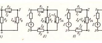
A mixed connection is a combination of the previously discussed simpler connections of serial and parallel. In Fig. Figure 1.22 shows an example of a mixed connection circuit. It is easily reduced to a single-circuit value. First, the equivalent resistance is calculated
parallel connected resistances and
or
From
we get
The resulting expressions are called the “shoulder rule.” They allow you to break the current
into two parallel currents and .
As a result of the transformations performed, we obtain a circuit with two series-connected resistances
and (Fig. 1.22.6). We sum up these resistances and get a single-circuit circuit (Fig. 1.22c) with a resistance equivalent to a mixed connection of resistances and .
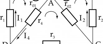
Let us consider the transformation of a triangle into a star using the example of a bridge circuit shown in Fig. 1.23, a. The circuit contains four arms
And . In measuring technology, a source is connected to one of the diagonals (between nodes 1 and 3), and a measuring device is connected to the second diagonal (between nodes 4 and 2). In the circuit under consideration, resistance is included in this diagonal.
Let
. It is required to calculate the resistance of the bridge circuit between points and .
The circuit does not contain series or parallel connections of elements, but has two passive triangles formed by resistances
and four stars, the centers of convergence of the rays of which are nodes 1, 2, 3, 4. Let us consider the procedure for calculating the resistance of the bridge circuit between nodes 1 and 3 using the triangle-star transformation.
First, the resistance triangle
replace it with an equivalent star (Fig. 1.23.6). In accordance with (1.9) resistance
Similarly, we calculate the resistance
And . We'll get it.
As a result of the transformations performed, we obtain the circuit shown in Fig. 1.23(6). Replacing series-connected resistors
and equivalent resistances and , we obtain the equivalent circuit shown in Fig. 1.23c. Resistance . Resistance .
From the equivalent circuit in Fig. 1.23, let's calculate the resistance of the bridge circuit between the points
And
To check the calculations, a DC analysis of the circuit shown in Fig. 1 was performed using the MicroCap circuit modeling program. 1.23, d. From those shown in Fig. 1.24 analysis results show that when connecting a bridge circuit to a source of constant EMF
a current of 1 A flows through the circuit. It follows that the bridge resistance between points and is equal to 10 Ohms, which confirms the calculation results.
This theory is taken from the electrical engineering assignment help page:
Electrical Help
Perhaps these pages will be useful to you:
| Basic laws of electrical circuits |
| Equivalent transformations of passive sections of an electrical circuit |
| Methods for calculating complex electrical circuits |
| Potential diagram in DC circuits |
DC electrical circuit
The algebraic sum of the voltage drops across resistive elements in any closed circuit is equal to the algebraic sum of the emf. A nonlinear element, such as an incandescent lamp, has a resistance, the value of which increases with increasing voltage, and therefore the current supplied to the lamp.
A source of electrical energy is characterized by the concept of emf E, which is understood as a value numerically equal to the energy received inside the source by a unit of electric charge.
When calculating, several main elements are distinguished in the electrical circuit diagram. This method is based on drawing up equations according to Kirchhoff's first law: Diagram of a complex electrical circuit with two nodes.
For different electrical devices, their nominal parameters are indicated.
An electrical circuit in short circuit mode has a resistance that is zero. In this diagram, real circuit elements are depicted by symbols, and auxiliary circuit elements are usually not depicted, and if the resistance of the connecting wires is much less than the resistance of other circuit elements, it is not taken into account.
As can be seen, when the sources are connected in parallel, the current and power of the external circuit are equal, respectively, to the sum of the currents and powers of the sources.
In the case of a series connection of resistances in a branch, in general, the equations of nodal potentials have the form: If there are current sources in the circuit, then the term on the right side will be equal to the sum of the current sources: The nodal potential method has an advantage if the number of independent nodes is less than the number of circuits. It is advisable to choose the same positive bypass directions in all circuits, for example, clockwise, as shown in Fig. Design and principle of operation of a DC motor. DC motor diagram.
Formulas for direct electric current
A direct electric current does not change in magnitude or direction. It is used to calculate a closed, homogeneous circuit, power and other parameters. Therefore, it is important to know the formulas for it and the basic laws associated with it.
You might be interested in: Features of touch voltage
Basic list of formulas
Ohm's law for a section of a homogeneous chain
For electric current to exist, a field is needed. For its formation, potentials or their difference, expressed by voltage, are needed. The current will be directed towards reducing the potentials, and the electrons will begin to move in the opposite direction. In 1826, G. Ohm conducted a study and concluded: the higher the voltage, the greater the current that passes through the section.
For your information! Adjacent conductors conduct electricity differently. That is, each element has its own conductivity, electrical resistance.
As a result, according to Ohm’s theorem, the current strength for a section of a homogeneous circuit will be directly proportional to the voltage across it and inversely proportional to the conductive resistance.
Ohm's law
Using the formula I = U / R, where I is considered to be the current strength, U is the voltage, and R is the electrical resistance, the latter value can be found if p * l / S, where p is the conductor resistivity, l is the length of the conductor, and S — cross-sectional area of the conductor.
Ohm's law for a closed circuit with a current source
Ohm made a formula for a closed circuit. According to it, the current in this section from a current source having internal and external load resistance is equal to dividing the electromotive force of the source by the sum of the internal and external resistance. It looks like this: I = e / R + r, where I is the current force, e is the emf, R is the resistance, and r is the internal resistance of the voltage source.
Note! In the physical sense, according to this law, the higher the EMF, the higher the source of energy, the greater the speed of movement of charges. The higher the resistance, the lower the current.
Ohm's law for a closed circuit
DC operation
Energy, when passed through a conductor, moves in an orderly manner into the carrier. While moving, it does work. As a result, direct current work is the field activity aimed at transferring electrical charges along a conductor. It is equal to I multiplied by the voltage and time performed by the work.
Joule-Lenz law
When electricity passes through any resistive conductor, heat is always released. The amount of heat released over a certain period of time is determined by the Joule-Lenz law. According to the formula, the heat power is equal to the electricity density multiplied by the voltage - w =j * E = oE(2).
Note! In practical terms, the law is important for reducing electricity loss, selecting a conductor for an electrical circuit, selecting an electric heating device and using a fuse to protect the network.
Joule-Lenz law
Apparent power developed by the current source
Power is work done in one second of time. Electrical power is a physical quantity that characterizes the speed of transmission with the conversion of electricity.
The work that is developed by the source of electricity throughout the circuit is total power. It can be determined by the formula P = El, where E is considered the emf, and I is the value of the current characteristic.
For your information! If there is a linear load, then the total power indicator is equal to the square root of the squares of the active and reactive work of the source. If there is a nonlinear load, then it is equal to the square root of the squares of the active and inactive work of the source.
Full power
In practical measurements, such work is expressed in kilowatts per hour. Used to measure electricity consumption in domestic and industrial environments, to determine the generated electrical energy in electrical equipment.
Net power
The maximum or useful power is that which is released in the external gap of the circuit, that is, during the load of the resistor. It can be used to perform any tasks. A similar concept can be applied to calculate how an electric motor or transformer works, which is capable of consuming active and reactive components.
You might be interested in Description of the KSPV cable
Net power
The useful power indicator can be calculated using three formulas: P = I 2R, P = U2 / r, P = IU, where I is the current strength in a certain section of the circuit; U is the voltage on part of the terminals (clamps) of the current source, and R is the load resistance or external circuit.
Current source efficiency
The efficiency of a current source is the division of the useful power indicator by the total. If the internal resistance of the source is equal to the external resistance, then half the results of all the work will be lost in the source, and the other half will be allocated to the load. In such a situation, the efficiency will be 50%.
If we consider this concept most fully, then when electric charges move along a closed electrical circuit, the current source performs a certain useful and complete work. By performing the first, it moves charges into the external circuit. Doing the second work, charged particles move throughout the area.
Current source efficiency
Note! A useful effect is achieved when the resistance of the external electrical circuit has a certain value, depending on the source and load. The ratio of useful work to full is expressed by the formula: η = Apolez / Apoln = Ppolez / Pfull = U/ε = R / (R + r).
Kirchhoff's first rule
According to Kirchhoff's first law, the current sum in any part of the electrical circuit is equal to zero. The directional charge towards the node is positive, and from it - negative. The algebraic current sum of charges that are directed towards a node is equal to the sum of those that are directed away from it. If we translate this rule, we can get the following definition: as much current enters the node, so much comes out of it. This rule follows from the law on the conservation of charged particles.
By solving linear equations based on Kirchhoff's rules, it is possible to find all current values and voltages in areas of direct, alternating and quasi-stationary electric currents.
Note! In electrical engineering, Kirchhoff's rule is of particular importance, since it is universal for solving many problems in the theory of electrical circuits. It can be used to calculate complex electrical circuits. Using it, you can obtain a system of linear equations for currents or voltages on all internodal branches of the circuits.
Kirchhoff's first rule
Kirchhoff's second rule
The second Kirchhoff rule follows from the first and third Maxwellian equations. According to it, the algebraic sum of the voltages on the resistive elements of a closed section is equal to the sum of the emf that is included in it. If there is no EMF in the area, then the total voltage drop is equal to zero. To put it even more simply, during a complete bypass of the circuit, the potential changes. It returns to its original value.
A common case for a section of one circuit is Ohm's law. When composing stress equations for a circuit, it is necessary to select its positive bypass. To do this, you need to know that when selecting a bypass, the branch voltage drop indicator will be positive if the bypass direction in the branch coincides with the one that was previously selected. If it does not match, then the branch voltage indicator will be negative.
Important! Kirchhoff's second rule can be used in a linear or nonlinear linearized circuit for any change in currents and voltages.
Kirchhoff's second rule
As a result, in order to understand the basics of physics, electrical phenomena, electrodynamics and successfully use knowledge in the process of life, you need to know the derived theorems, laws, formulas and rules in the field of electricity, which are presented above. For example, by imagining what this or that formula looks like, you can solve any problem in a textbook on physics or life.
Circuit elements
When comparing the external characteristics of the EMF source Fig. Three-phase circuit power 3.
Classical method for calculating transient processes 5. Depending on the electrical conductivity, all substances are divided into: 1.
Series connection in a circuit A large number of electrical circuits consist of several current receivers.
Matched mode The matched mode of the electrical circuit ensures maximum transfer of active power from the power source to the consumer. In the diagram this element looks like this: In this diagram, real circuit elements are depicted by symbols, and auxiliary circuit elements are usually not depicted, and if the resistance of the connecting wires is much less than the resistance of other circuit elements, it is not taken into account.
