Current transformer resistance to mechanical and thermal influences
The resistance of a current transformer to mechanical and thermal influences is characterized by electrodynamic resistance current and thermal resistance current.
Electrodynamic withstand current
The electrodynamic resistance current ID is equal to the greatest amplitude of the short circuit current for the entire duration of its flow, which the current transformer can withstand without damage preventing its further proper operation.
Current I D characterizes the ability of a current transformer to withstand the mechanical (electrodynamic) effects of short circuit current.
Electrodynamic resistance can also be characterized by the multiplicity KD, which is the ratio of the electrodynamic resistance current to the amplitude of the rated primary current.
Electrodynamic resistance requirements do not apply to busbar, built-in and detachable current transformers.
Thermal current
Thermal resistance current Itt is equal to the highest effective value of the short circuit current over the period tt, which the current transformer can withstand for the entire period of time without heating the current-carrying parts to temperatures exceeding those permissible for short-circuit currents (see below), and without damage preventing its further work.
Thermal resistance characterizes the ability of a current transformer to withstand the thermal effects of short-circuit current.
To judge the thermal resistance of a current transformer, it is necessary to know not only the values of the current passing through the transformer, but also its duration or, in other words, to know the total amount of heat generated, which is proportional to the product of the square of the current ItT and its duration tT. This time, in turn, depends on the parameters of the network in which the current transformer is installed, and varies from one to several seconds.
Thermal resistance can be characterized by the CT multiple of the thermal resistance current, which is the ratio of the thermal resistance current to the effective value of the rated primary current.
In accordance with GOST 7746-78, the following thermal resistance currents are established for domestic current transformers:
- one-second I1T or two-second I2T (or a multiple of them K1T and K2T in relation to the rated primary current) for current transformers with rated voltages of 330 kV and above;
- one-second I1T or three-second I3T (or a multiple of them K1T and K3T in relation to the rated primary current) for current transformers with rated voltages up to 220 kV inclusive.
There should be the following relationships between the electrodynamic and thermal resistance currents:
for current transformers with rated voltages of 330 kV and above
for current transformers for rated voltages up to 220 kV
Temperature conditions
The temperature of the current-carrying parts of current transformers at thermal current should not exceed:
- 200 °C for live parts made of aluminum;
- 250 °C for live parts made of copper and its alloys in contact with organic insulation or oil;
- 300 °C for live parts made of copper and its alloys not in contact with organic insulation or oil.
When determining the indicated temperature values, one should proceed from its initial values corresponding to long-term operation of the current transformer at the rated current.
The values of electrodynamic and thermal resistance currents of current transformers are not standardized by the state standard. However, they must comply with the electrodynamic and thermal resistance of other high-voltage devices installed in the same circuit with the current transformer. In table 1-2 shows data on the dynamic and thermal resistance of domestic current transformers.
Table 1-2. Data on the electrodynamic and thermal resistance of some types of domestic current transformers
Note. Electrodynamic and thermal resistance depends on the mechanical strength of the insulating and current-carrying parts, as well as on the cross-section of the latter.
Source
Thermal and electrodynamic resistance of electrical devices
⇐ PreviousPage 4 of 4
Equipment experiencing excessive thermal stress is at risk of premature failure. The heating of components and assemblies of electrical devices can occur so intensely that the heat will not be removed from the heated elements in a timely manner.
Thermal resistance of electrical devices is usually called their ability to overcome excessive thermal loads without damage to equipment components and conductive lines. The quantitative characteristic of thermal resistance refers to the thermal resistance current passing through the conductor over a certain period of time. The most unfavorable mode of operation of the device is short circuit mode, in which the value of current and power of heat sources sharply increases.
The electrodynamic resistance of electrical devices means the ability of this equipment to withstand the electrodynamic effect of short circuit current, without causing failures and other harmful consequences that negatively affect its operation.
Electrodynamic resistance is characterized by the rated current of electrodynamic resistance, the value of which is established based on the results of standard tests, namely: the effective and instantaneous value of the current.
When carrying out testing work for electrodynamic resistance, it is necessary to compare the rated current value with the calculated values.
Electrodynamic forces in electrical devices
If the operation of the electrical apparatus proceeds in optimal mode, the electrodynamic forces are very small and do not create any difficulties for the uninterrupted operation of the equipment. If a short circuit occurs, such forces can cause serious damage to electrical devices.
In order to avoid such situations, it is necessary to calculate the device or its individual components for electrodynamic stability. The need for such a calculation is due to another reason. The fact is that the implementation of new technical solutions to minimize equipment elements leads to the fact that current-carrying lines are in close proximity to each other, which increases the risk of a short circuit.
During normal operation, the temperature of current-carrying parts (elements) should not exceed the permissible temperature (values recommended by the relevant GOST or other regulatory documents).
The devices must withstand the thermal effects of short-circuit currents for a certain time. without any deformation that would prevent their further use (high wear resistance).
The insulation of the device must be calculated taking into account possible overvoltages that arise during operation, with a certain margin taking into account its “aging”.
Contacts of electrical devices must be capable of repeatedly switching on and off operating currents.
The devices must have high reliability and accuracy, the necessary speed, minimum weight, small dimensions, low cost, and ease of use.
BIBLIOGRAPHY
1. Rozanov Yu.K. "Power electronics." textbook for students universities. - M.: MPEI, 2009.
2. A.G. Godzello, Yu. K. Rozanov “Electrical and electronic devices” - M.: Academy, 2010
3. B.N. Neklepaev, I.P. Kryuchkov “Electrical part of power plants and
substations.” - M.: Energy, 1989.
4. M.V. Nemtsov, M.L. Nemtsov “Electrical engineering and electronics” - M.: Academy, 2013.
5. I.I. Aliev “Handbook of electrical engineering and electrical equipment.” - M.: Energoattomizdat, 1986.
6. “Rules for the installation of electrical installations.” - M.: Energoatomizdat, 1986.
7. A.D.Smirnov, K.M. Antipov “Reference book for power engineer”. - M.:
Energy, 1986
8. A.E. Zorokhovich, V.K. Kalinin “Electrical engineering with the basics of industrial electronics.” - M.: Higher School, 1975.
9. Methodological recommendations for completing a course project in the discipline electrical and electronic devices.
Educational institution of higher education
"SOUTH URAL INSTITUTE OF MANAGEMENT AND ECONOMICS"
REVIEWER CARD
COURSE PROJECT
By discipline
Electrical and electronic apparatus
Student
Group ElZ 301/05a Direction 03.13.02. Electrical power and electrical engineering
Inspection date " " April 2021
Rating good
Teacher Akishev A.N. _____________
(Last name, first name, patronymic) (signature)
REVIEW
The course project was completed at a good level and corresponds to the content of graduate training in this specialty.
The content of the work fully corresponds to the topic of the study; the positions of different authors, their analysis and evaluation are presented. The work uses various literary sources and documents.
The student exhibits deep general theoretical training. Demonstrates ability to work with various types of sources. Demonstrates the ability to generalize, systematize and classify material.
The student is able to determine the practical significance of the work and find options for using research materials in professional activities, analyze the results obtained and draw specific conclusions.
During the defense, the student was able to adequately present the results of the work in an oral presentation, showed good knowledge of the subject and mastery of scientific research skills.
⇐ Previous4
Recommended pages:
ELECTRODYNAMIC AND THERMAL STABILITY
Date added: 2015-07-23; ; Copyright infringement
The requirements for explosives to withstand the effects of short-circuit currents without damage are characterized by the concepts of electrodynamic and thermal resistance of the remote control.
Electrodynamic withstand current I
d determines the maximum possible mechanical (electrodynamic) forces arising from the flow of current through the current-carrying and contact systems of the remote control, which can not only deform the current-carrying and contact systems of the remote control, but also cause vibration of the contacts, which will ultimately lead to welding of the latter.
Since I
d =
K
d
I
o.
nom, where K
d = 2.5 is the coefficient of electrodynamic resistance, then the latter is valid (in accordance with GOST 52565-06) for networks with cos φ 2.3 s.
1.6. NOMINAL OPERATION CYCLES. SWITCHING RESOURCE
In the vast majority of cases, short circuits on lines that are not associated with insulation damage can be eliminated by interrupting the current for a time not exceeding 0.3 s required for deionization of the open short-circuit arc. In this case, it again becomes possible to turn on the installation under operating voltage. This implies the need to perform a remote control of a certain sequence of operations associated with disconnecting the damaged section of the network and then putting it back into operation. These are the so-called automatic reclosing cycles (AR):
O– t
bt – VO – 180 s – VO,
Normalized cycles of on and off operations
For circuit breakers designed to operate with automatic reclosure, the following cycles are standardized:
1) O - tbt - VO - 180 s - VO;
2) O - 180 s - VO - VO,
where O is the operation of switching off the short circuit; VO - switching operation on a short circuit and immediately (without a deliberate time delay) the following shutdown operation; tbt is the normalized no-current pause during automatic reclosure, the value of which for different types of circuit breakers can range from 0.3 to 1.3 s.
For circuit breakers not intended to operate with automatic reclosure, only the second cycle is installed.
What is electrodynamic withstand current?
GOST R 52736-2007
NATIONAL STANDARD OF THE RUSSIAN FEDERATION
Short circuits in electrical installations
METHODS FOR CALCULATING ELECTRODYNAMIC AND THERMAL EFFECTS OF SHORT CIRCUIT CURRENT
Short-circuits in electrical installations. Calculation methods of electrodynamics and thermal effects of short-circuit current
Date of introduction 2008-07-01
The goals and principles of standardization in the Russian Federation are established by Federal Law of December 27, 2002 N 184-FZ “On Technical Regulation”, and the rules for applying national standards of the Russian Federation are GOST R 1.0-2004 “Standardization in the Russian Federation. Basic provisions"
Standard information
1 DEVELOPED by the Branch of OJSC "STC of Electric Power Industry" - VNIIE, Moscow Energy Institute (Technical University) (MPEI (TU))
2 INTRODUCED by the Technical Committee for Standardization TC 437 “Short Circuit Currents”
Information about changes to this standard is published annually in the published information index “National Standards”, and the text of changes and amendments is published in the monthly published information index “National Standards”. In case of revision (replacement) or cancellation of this standard, the corresponding notice will be published in the monthly published information index “National Standards”. Relevant information, notifications and texts are also posted in the public information system - on the official website of the Federal Agency for Technical Regulation and Metrology on the Internet
Selection of conductors for resistance to short-circuit current.
Selection of conductors based on thermal and dynamic resistance to short-circuit current.
Conductors and current lines in electrical networks above 1000 V, as a rule, are subject to testing for heating conditions with short-circuit current. In electrical networks up to 1000 V, only current conductors are checked for thermal stability. An increase in the temperature of the cores of insulated conductors and cables as a result of the passage of short-circuit current. leads to chemical decomposition of the insulation and a sharp decrease in its electrical and mechanical strength, and consequently to the possibility of an accident. Therefore, certain maximum permissible temperature limits in short-circuit mode have been established, indicated in Table. 6-1.
Checking cables for heating from short-circuit currents. should be carried out: 1) for single cables of short length, based on the short circuit. at the beginning of the cable; 2) for single cables with couplings, based on the short circuit. s the beginning of each section in order to be able to reduce the cross-section of the cable along its length in steps; 3) for two or more cables connected in parallel, based on the short circuit. directly behind the beam (by the through current).
It is allowed not to check the conductors in the short-circuit mode. if they are protected by fuses. A line is considered to be protected by a fuse when the breaking capacity of the fuse is sufficient to interrupt the largest possible fault current of the line. For lines to individual electrical receivers, including workshop transformers with a total power of up to 1000 kVA inclusive, it is allowed not to check the cross-section of conductors for short-circuit current, while the following conditions are met:
1. Redundancy is provided in the electrical or technological part, guaranteeing against disruption of the production process. 2. Damage to conductors due to short circuit. cannot cause an explosion. 3. It is possible to replace conductors without significant difficulties.
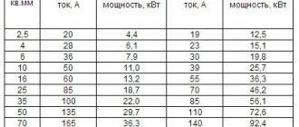
For lines to individual electrical receivers or small distribution points of non-essential purposes, it is allowed not to test conductors for thermal stability during a short circuit, if only one condition 2 is met (no danger of explosion). Wires of overhead lines up to 10 kV are not checked for short-circuit current. Permissible short-circuit current values. for cables are determined depending on the material and cross-section of the cable and the duration of passage of the short-circuit current. Thermal effect of short-circuit current during the actual time of its passage td, is characterized by the value of the fictitious time tf of passage of the steady-state short-circuit current. with the same thermal effect. The fictitious time is determined depending on the ratio where I" is the effective value of the periodic component of the short-circuit current. at the initial moment, and is the steady-state short-circuit current. (effective value), a. The actual time I d is composed of the time delay set on the overcurrent protection of the line and the own time of the disconnecting device (power switch). When checking the thermal stability of conductors of lines equipped with high-speed automatic reclosing, the increase in heating of the conductors due to an increase in the total duration of the short circuit must be taken into account. When calculating the short-circuit current. in distribution networks of 6-10 kV, attenuation is often not taken into account. In this case, the fictitious time can be taken equal to the real one, and the task of checking conductors for thermal stability is simplified by the absence of the need to determine the fictitious time. Cross section that ensures the thermal resistance of the conductor to short-circuit current. at a given value of fictitious time t f, is determined from the expression where F is the cross-section of the cable core, mm kV C - a constant determined depending on the specified PUE final heating temperature of the cores and voltage; numerical values of the constant C- are indicated in table. 6-1. Below is the table. 6-2 for testing cables for thermal stability, compiled according to formula (6-2) in the values of the permissible steady-state short-circuit current. in kiloamperes. In addition to calculating thermal stability, the cross-section of busbars must also be checked for mechanical strength during short-circuit. (dynamic stability of the conductor).
Electrodynamic resistance
9. Electrodynamic resistance
See also related terms:
1.1.5. Electrodynamic resistance to short circuit current
— the ability of electrical installations to withstand the action of short circuit shock current.
3.7 electrodynamic resistance of the starter:
The ability of a structure to withstand the effects of the highest short circuit current (amplitude value) during its flow without damage that prevents further proper operation of the starter.
9.1.37. Electrodynamic resistance of a transformer during a short circuit
The ability of a transformer to withstand without damage the dynamic effects that occur during an external short circuit
3.6. Electrodynamic resistance of switchgear cabinet
The ability of the cabinet structure and the electrical equipment, parts and elements installed in it to withstand the effects of the highest amplitude value of the short circuit current during its flow without damage interfering with the further operation of the switchgear
Dictionary-reference book of terms of normative and technical documentation. academic.ru. 2015.