The welding transformer circuit and the welding inverter circuit differ significantly from each other. In the second case, the base of early units for welding work consists of step-down transformers, which makes them bulky and heavy.
Today, modern equipment, due to frequent use during production, has become lightweight, compact, with a wide range of capabilities and features.
The main element in the electrical circuit of welding inverters is a pulsed converter, thanks to which high-frequency current is generated.
Inverter classification
Each individual type of welding work involves the use of certain inverter equipment, which must still be selected correctly. Each model has a welding inverter circuit with features, different characteristics from other units and a range of capabilities.
Equipment from modern manufacturers is equally used by enterprises in the manufacturing sector, as well as by hobbyists for domestic use.
Manufacturers regularly change the electrical circuit diagrams of welding inverters in order to improve them, provide them with new functionality and improve the quality of their technical characteristics.
Inverter equipment is the main device with which the following technological operations are performed:
- electric arc welding using a consumable or non-consumable electrode;
- plasma cutting;
- work with welding using semi-automatic or automatic technology.
In addition to the above, inverter equipment is also considered the most effective way to weld aluminum parts, stainless steel elements and other materials with difficult weldability.
Despite the individual characteristics of each model and each electrical circuit, as a result, the inverter for welding makes a high-quality, reliable and neat seam, regardless of the type of technology used.
It is also worth noting that it is compact and light in weight, so it can be used under any conditions and taken to any place where the welding process is carried out.
Features of the inverter
An inverter welding machine is a power supply that is now used in computers. Electrical energy is converted in the inverter as follows:
- The AC voltage is converted to DC.
- The constant sine wave current is converted into alternating current at high frequency.
- Voltage values decrease.
- The current is rectified while maintaining the required frequency.
This welding inverter circuit allows you to reduce its weight and dimensions. It is known that old welding machines work on the principle of reducing the voltage and increasing the current on the secondary winding of the transformer. Due to the high current strength, it is possible to weld metals using the arc method. To increase the current and reduce the voltage on the secondary winding, the number of turns is reduced and the cross-section of the conductor is increased. As a result, a transformer-type welding machine weighs a lot and has significant dimensions.
To solve this problem, a welding inverter circuit was proposed. The principle is based on increasing the current frequency to 60 or all 80 kHz. Due to this, the weight is reduced and the dimensions of the device are reduced. To implement the plan, it was necessary to increase the frequency by thousands of times, which became possible thanks to field-effect transistors. The transistors communicate with each other at a frequency of approximately 60−80 kHz. Their power supply circuit is supplied with direct current, which is provided by a rectifier, which is used as a diode bridge. Voltage equalization is provided by capacitors.
The alternating current is transferred to the step-down transformer after passing through the transistors. In this case, a coil reduced by hundreds of times is used as a transformer. The coil is used because the frequency of the current supplied to the transformer is already increased a thousand times by the field effect transistors. As a result, similar data are obtained as when using transformer welding, but with a large difference in dimensions and weight.
Inverter circuit for welding
Electrical circuit of a welding inverter
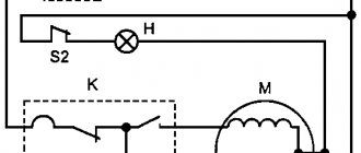
The circuit of an inverter welding unit has a special characteristic and functionality, which includes the following components:
- Control and indication body.
- System responsible for operating the thermal protection function and controlling the cooling fan. This also includes the fan of the inverter itself and a sensor with temperature indicators.
- Electrical circuit diagrams imply the presence of a PWM controller, consisting of a transformer with current, a sensor with load current.
- Power supply system for the low-current part of the electrical circuit of a hardware inverter for welding.
- A mechanism can be installed in the circuit converter, thanks to which power is supplied to the power system of the device. This includes a capacitive filter, a rectifier, and a nonlinear charging circuit.
- Power section with single-cycle converter. It also includes: a power transformer, a secondary rectifier and a choke for the current output.
Each description of the circuit diagram of a welding inverter should contain a brief description of all the constituent elements.
Elements of the electrical circuit of welding inverters
The electrical circuit diagram of an inverter welding machine involves a combination of several elements that are interconnected. The main ones can be called:
- The block responsible for supplying energy to the power section. This element is represented by a combination of several devices that are capable of changing current parameters to the required values. Typically, a capacitive filter and a rectifier are included.
- The device includes a power transformer. The power supply of the welding inverter also includes a 4n90 transistor.
- A separate element is responsible for powering the low-current part of the structure.
- To control the main parameters, a PWM controller is installed. It is represented by a combination of a load current sensor and a transformer.
- A separate block is responsible for protecting the structure from heat. When electrical current passes, some components may become very hot. Therefore, an additional cooling module is installed, represented by a fan and a temperature sensor.
- Control units that allow you to set basic parameters, as well as display elements.
Example of circuit diagram for current 250A
The diode bridge equipment for the welding machine is manufactured and installed taking into account the power of the device and some other points. Each device has its own characteristics, which we will consider in detail below.
Operating principle of the welding machine circuit
The main purpose of an inverter welding machine is to create a high-power current that is formed into an electric arc. That, in turn, melts the edges of the elements being welded and the filler material.
All this occurs across a wide range of design features. It is also worth noting that the welding machine diagram helps in the IPS repair of any device.
Inverter circuit for welding work.
Approximately the mechanism of action of the electronic circuit is as follows:
- A current with a variable frequency of 50 Hz passes through a regular electrical network into a rectifier, in which the current is converted into direct current.
- The current is then processed for smoothing through the use of a specialized system.
- After the filter, the current ends up in the inverter itself, which, in turn, must transform it back into alternating current, but adding a high frequency to it.
- Then, using a transformer, the voltage in high-frequency alternating current is reduced, thereby enhancing its effect.
In order to understand in more detail all the nuances of the circuit diagram of a welding inverter, it is necessary to study all the elements separately with their mechanism of action.
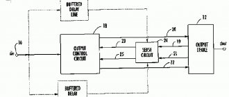
Schematic diagram of inverter-type devices
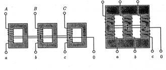
In order to understand the essence of the operation of a modern welding unit, it is necessary to know what blocks the schematic diagram of a welding inverter consists of, which provides energy for the short circuit arc during the welding process. These devices can be powered either from a three-phase 380V network or from a single-phase voltage of 220V. Moreover, fluctuations in the supply voltage can reach significant values, which does not affect the performance of the units. This allows you to work in unstable suburban power supply networks, which are quite often present in holiday villages.
An alternating voltage with a frequency of 50 Hz is supplied to the input of the device, where it is rectified and converted into high-frequency oscillations up to 70-85 kHz. This makes it possible, due to high-quality element base and compact transformers, to obtain pulsed and direct welding current at the output. This welding machine circuit consists of the following elements:
- low-frequency step-down rectifier unit with capacitor filter;
- adjustable inverter that converts direct current into high-frequency alternating current;
- a high-frequency transformer that outputs high-frequency or direct high-power welding current;
- a phase-shifting inductor that stabilizes the characteristics of the output voltage;
- a feedback circuit that controls the output parameters and a control unit that changes the welding current and voltage parameters.
It is extremely important to select a semiconductor base from reliable, proven manufacturers who provide high parameters for welding processes and ensure long-lasting service.
Powerful output transistors and diodes must have efficient heat sinks, which are cooled by forced ventilation, the intensity of which should depend on the welding load. Only in this case will it be possible to avoid malfunction of the power unit of the inverter apparatus. Also, impeccable operation is ensured by observing safe operation rules and timely maintenance of individual units and components. An important place is occupied by regular cleaning of dust from cooling radiators of power and semiconductor elements.
Advantages and disadvantages of inverter-type welding machines
An inverter welding machine, like any other equipment, has its advantages and disadvantages.
Diagram of an inverter type welding machine.
The main advantages of this equipment, which so skillfully replaced a conventional transformer, include:
- Due to a new approach to the production of inverter-type structures for welding metals, as well as new current control, most models weigh from 5 to 12 kilograms, in contrast to transformers, which weigh 18-35 kilograms.
- These devices have a fairly high efficiency rate. This is due to the fact that the device consumes a minimal amount of energy to heat all systems and mechanisms. For example, a welding transformer heats up quickly, which leads to overheating and equipment failure.
- In some transformer electrical circuits, as well as in inverters, welding can be carried out using electrodes, regardless of its type.
- The devices under consideration, due to their increased efficiency, consume half as much electricity as a simple transformer for welding.
- Many modern equipment have options in their structure, thanks to which the process of making mistakes by the master during technological work is minimized. Such options include anti-sticking and fast arc ignition.
- Some devices have a built-in programming function, thanks to which the master adjusts the operating mode during a specific type of welding process with precision and maximum efficiency.
- The high versatility of these designs is due to the regulation of all systems using current in a wide range. This makes it possible to use equipment that welds parts of different metals and performs the procedure using any technology.
The circuits of inverter welding machines also have disadvantages.
They are in the following aspects:
- Inverter welding equipment on the market is quite expensive, up to 50% more than the price of classic transformers for welding.
- The electrical circuit diagram of an inverter welding machine implies that most often a mechanism such as a transistor will break down. It is a rather vulnerable part, which entails repairs costing up to 60% of the cost of the entire equipment. From this we can conclude that repairs in themselves are an expensive pleasure.
- Since the basic electrical circuits of inverters for welding material are quite complex, experts do not recommend using them during bad weather or in the cold, so as not to damage the mechanisms and preserve the device for a long period. For welding work in the field or other open spaces, it is necessary to organize and build a special closed place with heating, where you can use this unit for welding.
Advantages and disadvantages of equipment
Devices based on the electrical circuit of an inverter welding machine have the following positive characteristics:
- Compact dimensions of the finished device. The devices weigh no more than 12 kg, which makes it easier to weld complex structures and work in hard-to-reach places.
- High efficiency, due to reduced energy consumption required to heat the mechanisms. Old-style devices quickly fail due to a constant increase in the temperature of the transformer.
- Availability of additional functions that eliminate errors during welding. These include anti-stick protection and automatic arc ignition.
- Possibility of programming some inverters. This function allows the welder to quickly set the equipment to the desired mode corresponding to the type of materials being welded.
- Versatility. Current adjustment over a wide range allows the use of inverters for welding elements made of various metals using any technology.
We recommend reading: How to choose electrodes for an inverter
Inverter devices also have disadvantages:
- High cost of units. Making it yourself helps reduce the cost of the device.
- Failure of transistors when assembling a welding inverter with your own hands. This is especially common when using affordable Chinese-made parts.
- Equipment maintenance and repair costs.
- Features of electrical circuits that do not allow the device to be used in difficult conditions, for example in frosty or windy weather. To work outdoors, a closed heated workplace is required.
Bottom line
For some specialists, a welding diagram provides an additional hint when assembling units for welding metals, which allows them to quickly complete the desired job. It is quite important to have basic knowledge of electrical engineering.
The availability of welding inverter circuits is determined by their principles, in other words, any master will need either instructions or drawings for assembly. It is worth noting that the electrical circuit diagrams place emphasis on achieving a high level of stability in the welding arc.
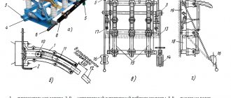
Welding inverter design
The structure of a homemade welding inverter, which determines the functionality and technical data, includes the following components:
- A power supply that supplies current to the power part of the device. The element consists of a filter, a converter and a nonlinear charging circuit.
- Power point. Assembled on the basis of a converter. A power transformer, rectifier, and inductor are also introduced into this part of the circuit.
- The unit that powers the components of the low-current inverter system.
- PWM controller. This unit includes a load current sensor.
- A block required to protect against overheating. This part of the electrical circuit controls the cooling fans. It includes temperature sensors that quickly respond to parameter changes.
- Indicating and control elements.
We recommend reading How an inverter welding machine works
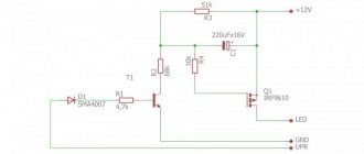
Inverter circuit
The electrical circuit of the welding inverter consists of transistors, which are powerful and take on most of the work. The frequency of the current in the network is only 50 Hz, but the transistors switch at a high frequency, so it is necessary to provide them with a constant voltage supply. This is where the rectifier comes into play, ensuring that the incoming current has constant parameters.
This effect is achieved by a diode bridge and filter capacitors. The diode bridge is very powerful, so there is a need to pair it with a cooling radiator. It, in turn, is equipped with an overheating fuse, which opens when critical temperatures are reached. It is necessary in order to avoid damage to the device due to overheating. Thus, at the first stage we receive a direct current at the output from the rectifier with a value of more than 220V.
An important element of the circuit is an electromagnetic compatibility filter; it is placed in front of the rectifier and protects the network from high-frequency interference that appears due to the operation of the inverter.
The inverter itself consists of two transistors on heat sinks to control heat. To reduce the voltage, a simple welding inverter circuit works successfully with a high-frequency transformer. Next, the transistors switch the DC voltage through the transformer winding, the values reach approximately 340V.
Quite simply, the role of the transformer is that the primary winding produces high voltage and small current, and the secondary winding produces less voltage, but the maximum current, the indicators can be about 120 amperes.
The output rectifier is a high-speed diode, dual, with a common cathode. The electrical circuit of an inverter welding machine requires fast-acting diodes, the essence of their work is that they open and close very quickly, this is necessary in order to protect the diodes themselves and the entire device from overheating and failure.
When the inverter is turned on, the capacitors begin to charge, since at this moment the charging current is very high, so much so that it can damage the diode bridges, a charge limiting circuit is used, also called a “soft start”. Its operation is based on a resistor having a high resistance; it is this that takes the brunt of the blow and is responsible for limiting the current in the circuit.