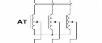
Recovery system with storage capacitor
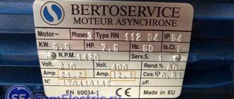
The braking period of the car lasts a fairly short time. Therefore, due to the technological features of the design of modern rechargeable batteries (or rather, the chemical processes that occur when they are recharged), it is quite difficult to store a large amount of energy in them. Mazda has developed a recovery system using a storage capacitor. During braking, a special generator with a voltage of 12÷25 V charges the capacity in a short period of time. Next, the accumulated energy is converted through a converter (DC/DC) into the usual 12 V and is supplied either to various consumers (air conditioner, CD player, etc.), or recharges the standard battery. According to the manufacturer, fuel savings are at least 10%.
Braking of asynchronous motors
What is recuperation in relation to asynchronous machines? In this case, this is only one type of braking. The other two are:
- dynamic deceleration;
- counter braking.
Each of them has its own characteristics.
Regenerative braking of an asynchronous motor
An induction motor (IM) turns into a generator when the rotor slip in the stator field increases. This can be done in three ways:
- reducing the frequency of the supply voltage, at which the rotor begins to rotate at a speed faster than synchronous;
- in machines with two or more rotation speeds, when switching windings or changing the number of switched poles;
- in motors with a wound rotor, by changing the resistance included in the circuit of the rotor windings.
The amount of slip in all cases exceeds unity, and the machine goes into generation mode and returns energy.
Opposition
This method is rarely used due to the disadvantages associated with the need to swap phases with each other. This causes a change in direction of movement, but the operating current increases tenfold. In addition, it is necessary to stop further supply of voltage so that after braking the engine does not rotate in the opposite direction.
Dynamic braking of an asynchronous motor
This reduction in rotation speed is obtained by applying a constant voltage to the stator winding. The resulting magnetic field from the stator acts on the rotor windings. EMF appears in them, and current begins to flow. The strength of the braking torque that occurs when the power released is directly dependent on the rotation speed of the electric motor. The engine turns into a generator with short-circuited output terminals and supplies energy to the network.
Replacing or supplementing a mechanical brake with regenerative deceleration allows energy to be recovered for reuse. Recovery, as one of the ways to save raw materials and energy, allows you to increase the economy and efficiency of technological processes.
Back braking
Back braking is used to quickly stop the engine. This can be done in several ways. In the first method, with the engine running, two phases are swapped by turning off contactor K1 and turning on K2. In this case, the direction of rotation of the stator magnetic field changes to the opposite. A large braking torque occurs and the engine stops quickly. But in order to limit large currents at the moment of increasing braking torque, it is necessary to introduce additional resistance into the stator or rotor winding.
In the second method, the engine is used as a brake for the load. That is, if the load goes down, then the engine should work, on the contrary, to rise. To do this, a large additional resistance is introduced into the motor rotor circuit. But its starting torque turns out to be less than the load torque, and the engine operates at a certain low speed, thereby ensuring a smooth descent.
In essence, counter-switch braking is carried out according to the engine reverse circuit.
Oh no, there's been an error
The presence of a large number of strong magnets in the direct drive motor and the absence of an overrunning clutch leads to the fact that the motor significantly slows down the bicycle wheel even in the absence of power. And when the engine operates in generator mode, this braking can be compared to driving up a fairly steep hill. Moreover, the speed of movement should be about 20 km/h. At a speed of 20 km/h, the battery charging current will be about 2 amperes. (At this current, a battery with a capacity of 10 A/hour will be charged in 5 hours.) The cyclist must develop a power of 2A*48V= 96 W. However, this does not take into account losses in the energy conversion system and losses during charging. And they make up about 50%. In other words, the cyclist needs to develop twice the power to charge the battery - approximately 180 W. It should also be taken into account that to move at this speed on a regular bicycle, a cyclist must produce about 100 watts of power. The total power required from the cyclist to charge the battery and travel at a speed of at least 20 km/h will be about 180 + 100 = 280 W. For reference: - a good athlete cyclist can produce short-term power of 500-600 W; — when driving uphill with a large slope, an untrained person can briefly output power of 220-290 W; It is not difficult to conclude that riding a bicycle in this mode for any length of time is unrealistic.
It is not without reason that almost all factory-made electric bicycles are installed not with direct drive motors capable of operating in generator mode, but with motors with a gearbox and overrunning clutch. And this is not without reason. If we compare the efficiency of these two motors, we can see that gear motors are more than 30% more efficient in using the energy stored in the battery than direct drive motors, and they do not slow down when there is no power. In addition, geared motors are twice as light when compared to motors with equivalent torque. For this reason, almost all mass-produced electric bicycles are equipped with only gear motors. Compare: - using a direct drive motor and a recuperation system, you can return a maximum of 5% of energy to the battery, and if you use a gear motor, you can save 30% of the energy stored in the battery, in other words, drive a distance 30% more than direct drive motor. And your bike will be significantly lighter. The choice, as they say, is obvious. By using a wheel motor with a geared motor as the driving force on a bicycle, the idea of energy recovery on an electric bicycle can be successfully forgotten, while gaining about 30% of the mileage on one charge.
We advise you to study Magnetic starter
Direct drive motors are logical to use if your goal is speed and you are not very concerned about the economic side of the issue. In this case, this engine will not have competition from its geared counterpart. If you need a speed of more than 50 km/h, get ready to take a motor with a power of 1000 - 1500 W (maximum power 1500-2500 W) complete with an energy-intensive, heavy and expensive battery. The battery should be rated for 20-30 A discharge current. The bike will be very heavy. It won't be a bicycle anymore. It's more like a scooter.
METHODS OF BRAKING AN INDUCTION MOTOR
Forced electrical braking of the motor can be carried out both when powered from an alternating current network, and by connecting the stator circuit to a direct current source (dynamic braking), as well as when it is self-excited. In all cases, engine braking is carried out by switching it to generator mode, in which it develops braking torque on its shaft, which expands the capabilities of the electric drive when controlling the movement of the executive bodies of working machines.
When the motor is powered from an alternating current network, back-switch braking and regenerative braking can be performed.
Back braking
can be implemented in two ways.
The first of them is associated with a change in the alternation of the two phases of the voltage supplying the motor on the stator. Let's say the engine operates at mechanical characteristic 1
at point
a
(Fig. 5.25,
a)
with alternating voltage phases on the stator
ABC.
Then, when switching two phases (for example,
B
and C), the engine switches to characteristic
3
at point
d,
section
db
of which corresponds to back-on braking. Note that when braking is implemented, additional resistors are connected to the rotor or stator circuit to limit the motor current and torque.
Rice. 5.25. Mechanical characteristics for counter-switch braking (o) and regenerative braking (b): 7 - initial characteristic; 2.3 - braking characteristics
Regenerative braking
is carried out in the case when the motor rotor speed exceeds synchronous speed and it operates in generator mode in parallel with the network, giving (recovering) energy to the network.
This mode occurs when a two-speed motor transitions from high to low speed, as shown in Fig. 5.25, b.
Let us assume that in the initial position the engine was operating at characteristic
1
at point
a
, rotating at speed 1.
As the number of pole pairs increases, the asynchronous motor switches to characteristic 2
at point
b,
section bc
of
which corresponds to braking with energy recovery (return) to the network.
The same type of braking can be implemented in the “frequency converter-motor” system when braking, reversing, or transitioning the motor from characteristic to characteristic. To do this, the frequency of the output voltage of the inverter and thereby the synchronous speed are reduced. Due to mechanical inertia, the current speed of the engine co will change more slowly than the rotation speed of the magnetic field co, and will exceed it. Due to this, a regenerative braking mode arises with the release of energy into the network. This braking mode is discussed in more detail in subsection 5.9.
Regenerative braking is the most economical type of engine braking, since it is accompanied by the generation of electrical energy by the engine, which can be used by other consumers.
Dynamic braking.
To implement dynamic braking mode, the motor stator winding is disconnected from the AC mains and connected to a DC source, as shown in Fig.
5.26, a.
In this case,
the rotor winding of motor
1 3
with a resistance of /?2d is connected to its circuit.
Rice. 5.26. Connection diagram (a) and characteristics (b) of an asynchronous motor during dynamic braking:
7 - engine; 2
- adjustment resistor;
3
- resistor in the rotor circuit;
4-6
- artificial mechanical characteristics; 7 - electromechanical characteristic
Parameters of the operating mode of the AC traction network during energy recovery
The inverter, which converts the recuperation electricity from the direct current of the traction motors into the alternating current of the electric power station, is located on the EPS and belongs to the category driven by the network.
When regenerating electricity at an alternating current of 25 kV, the active recuperation energy is generated by the EPS in the electric power plant, and the reactive energy is consumed from the external power supply network in the same way as in traction mode. This increases the reactive power consumption of electric locomotives in the intersubstation area.
————->P ¦ Mode
————->Q ¦ thrust
—————————————————
————->Q ¦ recovery
Rice. Directions of electricity in traction and recovery modes of EPS.
The angular shifts between the current and voltage of the EPS in the traction mode are for diode EPS φE = 370 el, for thyristor EPS φE = 420 el. The reactive power factor for the traction mode tg φE = Q/P for diode EPS is tg 370 = 0.754, for thyristor EPS - tg 420 = 0.9. Consequently, the reactive power consumption of the EPS in traction mode is QT = (0.75÷ 0.9)P. Reactive power consumption in traction mode is (75÷ 90)% of the active one.
The angular shifts between the current and voltage of the EPS in the recovery mode are φE = 60 el. gr. The reactive power factor for the recuperation mode tg φЭ = Q/P is tg 600 = 1.73. Consequently, the reactive power consumption of EPS in recovery mode is QР = 1.73P. Reactive power consumption in recuperation mode is 170% of the active one.
When working together in the inter-substation zone of the EPS in traction and recuperation modes, reactive power consumption increases significantly. The optimal mode in the intersubstation zone corresponds to the equality of active power consumption of EPS in traction modes Рт and active generation in recovery modes Рр (Рт = Рр). In this case, the reactive power for traction is Qt = 0.9P, the reactive power for recovery is Qp = 1.73Pt and the total reactive power consumption is Q∑ = (0.9 + 1.73)Pt = 2.63Pt. Ratio K = 2.63/0.9 = 2.92. Consequently, reactive power consumption in the intersubstation zone in the optimal recovery mode increases by 3 times. Since the ratio of active power consumption of EPS in traction and generation modes changes, it should be assumed that reactive power consumption increases in the range of 1.7 ÷ 3 times compared to traction mode.
Let's consider linear and vector diagrams of the current and voltage of the traction network in traction and recuperation modes with one-way power supply to the contact network.
Traction mode.
Rice. Linear diagram of the current and voltage of the EPS in traction mode: E1, U1 – curve of the EMF and voltage of the EPS transformer; i1t – current curve, i1(1) – first harmonic current curve.
Voltage loss in traction mode
∆ Uts = It RTS cos φT + It Xts sin φT = Iat RTS + IрХTS.
Source voltage
U1 = Ueps + ∆ Uts.
Recovery mode.
Rice. Linear diagram of the current and voltage of the EPS in recuperation mode: E1, U1 – curve of the EMF and voltage of the EPS transformer; i1Р – current curve, i1(1) – first harmonic current curve.
| Rice. Vector diagram of current and voltage in recuperation mode: Ie – total current value; Ira, Ipp – active and reactive components of the EPS current; φр – angular shift between current and voltage. |
Regenerative frequency converter device with synchronous rectifier
The power elements of the input converter of a conventional “irreversible” electronic speed controller consist of an uncontrolled diode bridge or a controlled diode-thyristor rectifier, which excludes the return of electricity to the supply network. The power elements of the Regenerative POWERDRIVE input converter consist of six special IGBT modules connected back to back. This assembly, controlled by a special regeneration controller, forms a synchronous rectifier that not only converts the AC supply voltage into a controlled DC voltage, but also allows the energy to flow back into the supply network. This reversible regulator has on its three inputs a 3-phase voltage system generated by pulse-width modulation (PWM), which is coordinated with the supply network through a “rectifier” choke. An RFI filter and a signal filter installed in series eliminate residual current components in the input converter.
SMART recovery systems
How does this so-called “smart” system work? When accelerating the vehicle, when the engine experiences increased loads, the standard generator is switched off. This allows the engine to gain speed faster and consume less fuel. When braking, the generator is switched on and energy is recovered. While driving, the electronics “monitor” the battery capacity. When it decreases (up to 75% of the nominal value), the generator automatically turns on to recharge the battery.
Braking of asynchronous motors
Reducing the speed of asynchronous electric motors is carried out in three ways:
- recovery;
- opposition;
- dynamic.
Regenerative braking of an asynchronous motor
Regeneration of asynchronous motors is possible in three cases:
- Changing the frequency of the supply voltage. Possible when powering the electric motor from a frequency converter. To switch to braking mode, the frequency is reduced so that the rotor rotation speed is greater than synchronous;
- Switching windings and changing the number of poles. Possible only in two- and multi-speed electric motors, in which several speeds are provided structurally;
- Power descent. Used in lifting mechanisms. These devices are equipped with electric motors with a wound rotor, the speed of which is adjusted by changing the value of the resistance connected to the rotor windings.
We advise you to study Soldering station on Arduino
In any case, when braking, the rotor begins to overtake the stator field, the slip becomes greater than 1, and the electric machine begins to work as a generator, delivering energy to the network.
Scheme of an electric motor with a wound rotor
Opposition
The counter-switching mode is carried out by switching the two phases powering the electric machine between each other and turning on the rotation of the device in the opposite direction.
It is possible to switch on with counter-connection of additional resistances in the stator circuit or wound rotor windings. This reduces current and braking torque.
Important! In practice, this method is rarely used due to currents exceeding 8-10 times higher than rated (with the exception of motors with wound rotor). In addition, the device must be turned off in time, otherwise it will begin to rotate in the opposite direction.
Dynamic braking of an asynchronous motor
This method is carried out by applying a constant voltage to the stator winding. To ensure trouble-free operation of the electric machine, the braking current should not exceed 4-5 no-load currents. This is achieved by including additional resistance in the stator circuit or using a step-down transformer.
Direct current flowing in the stator windings creates a magnetic field. When it crosses, an EMF is induced in the rotor windings and current flows. The released power creates a braking torque, the strength of which is greater, the higher the rotation speed of the electric machine.
In fact, an asynchronous electric motor in dynamic braking mode turns into a direct current generator, the output terminals of which are short-circuited (in a machine with a squirrel-cage rotor) or connected to an additional resistance (an electric machine with a wound rotor).
Dynamic braking circuit of an asynchronous electric motor
Regeneration in electric cars is a type of braking that allows you to save energy and avoid wear and tear on mechanical brakes.
Dynamic (electrodynamic) braking
If you disconnect the motor from the AC power supply and connect it to a DC source, dynamic braking will occur. The stator winding, when direct current flows, will create a stationary magnetic field. When rotating in such a field, an EMF will be induced in the rotor, under the influence of which a current will flow. This current will interact with the stationary field of the stator and create a braking torque, which will be directed against the direction of rotation of the rotor. As a result, the engine will gradually stop, and the speed of its stopping will depend on the strength of the direct current flowing through the stator, and, of course, on the stored kinetic energy of the electric drive. This energy, converted into electrical energy, is dissipated in the form of heat on the rotor.
In a motor with a wound rotor, the magnitude of the braking torque, and therefore the braking speed, can be changed by changing the value of additional resistances in the rotor circuit.
How does the recovery system work?
To operate, this system must provide power to the electric motor and return energy during braking. This is most easily done in urban electric vehicles, as well as in older electric vehicles equipped with lead batteries, DC motors and contactors - when downshifting at high speed, the energy return mode is automatically activated.
In modern transport, a PWM controller is used instead of contactors. This device allows you to return energy to both direct and alternating current networks. During operation, it acts as a rectifier, and during braking it determines the frequency and phase of the network, creating a reverse current.
Interesting. When dynamic braking of DC electric motors occurs, they also switch to generator mode, but the generated energy is not returned to the network, but is dissipated in the additional resistance.
Generator braking
Braking modes of asynchronous machines
When operating many production mechanisms, there is a need to quickly stop (braking) the engine. Mechanical brakes are widely used for this purpose, but an asynchronous machine can itself perform the functions of a braking device, operating in one of the braking modes. In this case, mechanical brakes are used as spare or emergency brakes, as well as to keep the mechanism stationary.
The following braking modes of asynchronous machines are distinguished:
- regenerative braking;
- dynamic braking;
- counter braking.
The machine switches to generator mode if n > n0, i.e. if the rotor rotates faster than the magnetic field. This mode can occur when regulating the rotation speed by increasing the number of pairs of poles or reducing the frequency of the power source, as well as in lifting and transport machines when lowering a load, when, under the influence of gravity of the load, the rotor begins to rotate faster than the magnetic field.
In generator mode, the direction of the electromagnetic moment changes, i.e. it becomes braking, causing a rapid decrease in rotation speed. At the same time, the phase of the current in the stator winding changes, which leads to a change in the direction of transmission of electrical energy. In generator mode, energy is returned to the network.
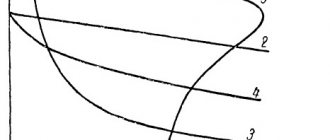
In Fig. Figure 2.25 shows the mechanical characteristics during regenerative braking due to lowering the load (a) and lowering the frequency of the power source (b).
Rice. 2.25
Let the engine with a given load on the shaft operate at point A (Fig. 2.25 a). If, under the influence of a lowered load, the rotor begins to rotate faster than the magnetic field and the operating point falls at point B, then nв > n0, the machine will develop a braking torque and the rotation speed will decrease to a value less than n0. One of the advantages of generator braking in asynchronous machines is that the transition to generator mode occurs automatically as soon as the rotor begins to rotate faster than the magnetic field. This protects asynchronous motors from an emergency situation that can occur with DC motors. Asynchronous motors cannot go into overdrive. The maximum rotor speed is limited by the speed of the magnetic field.
Let the engine operate with a given load on the shaft at point A of characteristic 1 (Fig. 2.25 b). When the frequency of the power source decreases, the operating point should move to point C of characteristic 2. But if nA turns out to be greater than the new reduced frequency of rotation of the magnetic field n02, then the machine from point A moves to point B, working in section B - n02 in generator mode. Due to this, a rapid reduction in rotation speed occurs. In section n02 - C, the machine operates in engine mode, but a further decrease in rotor speed occurs until the torque becomes equal to the load torque (t.C). A new state of equilibrium with a given load occurs at point C. Generator braking is the most economical mode, because Mechanical energy is converted into electrical energy and energy is returned to the network. One of the advantages of this braking mode is its spontaneous appearance, i.e. no monitoring equipment is required.
Application of recovery in transport
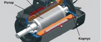
Operating principle of the electric motor
This braking method has been used for many years. Depending on the type of transport, its application has its own characteristics.
In electric cars and electric bicycles
When driving on the road, and even more so off-road, the electric drive operates almost all the time in traction mode, and before stopping or at an intersection - “coasting”. Stopping is done using mechanical brakes due to the fact that recuperation is ineffective at low speeds.
In addition, the efficiency of batteries in the charge-discharge cycle is far from 100%. Therefore, although such systems are installed on electric vehicles, they do not provide great battery savings.
Regeneration scheme in a car
On the railway
Recuperation in electric locomotives is carried out by traction motors. At the same time, they turn on in generator mode, converting the kinetic energy of the train into electricity. This energy is given back to the network, in contrast to rheostatic braking, which causes the rheostats to heat up.
Recuperation is also used during long downhill runs to maintain a constant speed. This method saves electricity, which is fed back into the grid and used by other trains.
Previously, only locomotives operating on DC power were equipped with this system. In devices operating from an alternating current network, it is difficult to synchronize the frequency of the supplied energy with the frequency of the network. Now this problem is solved using thyristor converters.
Train recuperation mode
In the underground
In the subway, while trains are moving, cars are constantly accelerating and braking. Therefore, energy recovery has a great economic effect. It reaches a maximum if this happens simultaneously in different trains at the same station. This is taken into account when creating the schedule.
In city public transport
In urban electric transport, this system is installed in almost all models. It is used as the main one up to a speed of 1-2 km/h, after which it becomes ineffective and the parking brake is activated instead.
In Formula 1
Since 2009, some cars have been equipped with a recovery system. This year, such devices have not yet provided tangible superiority.
In 2010, such systems were not used. Their installation, with restrictions on power and the amount of recovered energy, resumed in 2011.
Dynamic braking of an asynchronous motor
It is carried out by supplying direct current to the stator of an asynchronous motor after disconnecting the stator from the alternating current network by contactor KM1.
Dynamic braking can be carried out both for a motor with a squirrel-cage rotor and for a motor with a wound rotor. Moreover, for a motor with a wound rotor, resistance can be included in the rotor circuit or the rotor can be short-circuited without resistance.
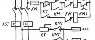
Diagram of dynamic braking of an asynchronous motor.
Braking characteristic of an asynchronous motor during dynamic braking: curve 7 - electromechanical characteristic, curves 4-6 mechanical characteristics.
When direct current is supplied to two phases of the stator winding, a constant magnetic field is created in the air gap of an asynchronous motor. When the rotor enters this field, a constant EMF is induced in it, directed towards the EMF of the rotating magnetic field, and the rotor slows down.
During this braking, the engine operates in generator mode, independent of the AC mains, and converts the kinetic energy of the moving parts of the electric drive into electrical energy, which is dissipated as heat in the rotor circuit.
The dynamic braking process can be controlled, that is, the braking time can be changed in two ways. For asynchronous electric motors with squirrel-cage rotor, the braking current can be varied. For motors with a wound rotor, you can change the value of the additional resistance in the rotor circuit.
The disadvantage of dynamic braking is the asymmetry of the magnetic field during braking, since direct current enters only two phases. Asymmetry causes the car to vibrate during braking.
In machines with a power of more than 100 kW, in order to avoid vibration, by complicating the power circuit, direct current is supplied to all three phases. But this greatly complicates and increases the cost of the drive.
Source
Other schemes for recuperating electricity into the grid
Another way to return electricity to the network is the “C-Light 4 Quadrant” technology patented by Leroy-Somer for direct connection of IGBT transistors to the supply network. This eliminates input filters and the need for a cumbersome DC bus precharge circuit.
This leads to a significant reduction in the dimensions of the regenerative frequency converter. In addition, stabilized voltage in the DC link makes it possible to significantly reduce the size of capacitors in the DC link and change their type from electrolytic to solid-state film.
As a result, the regenerative frequency converter, designed and manufactured using the C-Light 4 Quadrant technology, has almost half the dimensions compared to a standard frequency converter with a 6-pulse rectifier.
We advise you to study Checking the voltage in the outlet
About Emerson
About Emerson Industrial AutomationTM
About Leroy-Somer
Recovery system with storage capacitor
The braking period of the car lasts a fairly short time. Therefore, due to the technological features of the design of modern rechargeable batteries (or rather, the chemical processes that occur when they are recharged), it is quite difficult to store a large amount of energy in them. Mazda has developed a recovery system using a storage capacitor. During braking, a special generator with a voltage of 12÷25 V charges the capacity in a short period of time. Next, the accumulated energy is converted through a converter (DC/DC) into the usual 12 V and is supplied either to various consumers (air conditioner, CD player, etc.), or recharges the standard battery. According to the manufacturer, fuel savings are at least 10%.
Regenerative braking
Electric traction motors used to drive urban and railway electric vehicles operate using regenerative braking (BR). At the moment when the electric motor brakes, it turns into a generator.
Similar electric motors are used:
- in trolleybuses;
- on trams;
- in electric trains.
The electrical energy generated during the braking process is transferred back to the general power grid.
Attention! In a similar situation, electric or hybrid vehicles use this energy to charge their own battery. Electric train with RT engines
Electric train with RT engines
Regenerative braking
Rotation speed: formula
One type of braking is regenerative. In this case, the rotation speed of the electric motor is greater than that specified by the network parameters: the voltage on the armature and field winding in DC motors or the frequency of the supply voltage in synchronous or asynchronous motors. In this case, the electric motor switches to generator mode and releases the generated energy back into the network.
The main advantage of the recuperator is energy saving. This is especially noticeable when driving around the city with constantly changing speeds, commuter electric transport and subways with a large number of stops and braking in front of them.
In addition to its advantages, recovery has disadvantages:
- impossibility of completely stopping transport;
- slow stop at low speeds;
- lack of braking force when parking.
To compensate for these shortcomings, vehicles are equipped with an additional mechanical brake system.
Regenerative (generative) braking
Regenerative braking is used mainly as a brake before the main braking, or when lowering loads, for example in elevators.
For regenerative braking to occur, the rotor speed must exceed the synchronous speed. In this case, the engine will begin to supply energy to the network, that is, it will become an asynchronous generator. In this case, the electromagnetic torque of the motor becomes negative and has a braking effect.
Generator braking can be achieved in several ways. For example, in two-speed engines, when switching from a higher speed to a lower one. In this case, the rotor rotates by inertia at a frequency higher than the new synchronous frequency. A braking torque will occur, which will reduce the speed to the new nominal speed.
Let us assume that at the initial moment of time our engine was operating at characteristic 1 at point A, after switching the speed to a lower one, it switched to characteristic 2 at point B, and then, under the influence of the braking torque, reached point C, at a lower speed.
Generator braking can be achieved by reducing the frequency of the motor supply. This is possible if the motor is powered by a thyristor frequency converter. As the voltage frequency decreases, the synchronous rotation speed decreases. The rotation speed of the rotor, which rotates by inertia, will again be higher, and a braking torque will arise, which will reduce the rotor speed. In this way, the engine can be brought to a complete stop.
Application of recovery in transport
When electric vehicles operate, electric current energy is recovered. Each type of transport has its own design nuances.
In electric cars and electric bicycles
An electric bicycle, like a private electric car, although equipped with a system for returning electricity to the battery, has low efficiency. The electric drive of these vehicles consumes energy when moving. Since the braking mode is very rare and short-term, the share of the returned electricity is small. With its help, they only increase the mileage on one battery charge.
On the railway
During recuperation, traction motors of electric locomotives switch to the mode of generating electricity, which is returned to the network.
Important! The use of a PWM controller in the recuperation system instead of contactors allows you to return energy to any network: direct or alternating current. The controller operates in two modes
When moving, it rectifies the current; when braking, having determined the frequency and phase of the network, it releases electricity.
In the underground
When recovering electricity in the subway, a properly selected train schedule provides significant savings. The alternating acceleration and deceleration of a train can be synchronized with several trains on different branches and return energy to the network to the maximum.
In city public transport
All models of trolleybuses and trams are equipped with a similar braking and energy recovery system. There is a limit on the lower limit of the braking speed. It is 1-2 km/h. Next, the mechanical parking brakes come into play.
In Formula 1
In 2014, Formula 1 regulations implied a transition to turbo engines with an ERS system. This is double recovery, as a result of which both the kinetic energy during braking and the thermal energy of the exhaust are used. In this case, the ERS-K and ERS-H modules are used. The system includes two additional generators: MGU-K and MGU-H. The letters K and H represent kinetic and thermal energy, respectively.
What is energy recovery
For vehicles powered by electricity, the key parameter is range. The larger the battery capacity, the further the car will travel without recharging. The range between charges is even more important than the maximum speed, so manufacturers pay close attention to the battery. But it is simply impossible to endlessly increase the battery capacity: the higher the charge becomes, the more the battery weighs. That's why the idea of recharging on the go seems very attractive. And here we are talking about recovery.
The word "recuperation" comes from the Latin "recuperatio" (receiving back). This is the return of part of the spent energy for secondary use.
The technology is in demand in electric vehicles, especially those operating on batteries. When driving downhill and when stopping, the recovery system returns kinetic energy back to the battery and recharges it. This allows the car to travel a much longer distance.
Hydraulic recovery system
A vehicle with a hydraulic energy recovery system is equipped with a special pump motor and two hydraulic accumulators (low and high pressure). Principle of operation:
- When you press the brake pedal, the pump connects to the vehicle's transmission and pumps fluid from a low-pressure hydraulic accumulator into a cylinder filled with nitrogen gas (which is a kind of energy storage device). The gas is compressed and the pressure in the container increases. The force required to operate the pump slows down the vehicle and “helps” it stop.
- Until the driver presses the gas pedal again, the fluid remains under pressure in the battery. After this, it enters the pump motor and transfers (via the transmission) the stored energy to the wheels of the car.
The developers claim that the use of such recovery systems makes it possible to “return” to the car up to 80% of the energy that is usually “wasted” during braking. However, the significant size and weight of additional equipment that must be installed on the vehicle to implement such a regenerative braking system limit its use. Therefore, at present it is used only on heavy vehicles and public urban transport operating in a mode of frequent stops and restarts.
https://electrik.info/main/fakty/1172-rekuperaciya-elektricheskoy-energii.htmlhttps://mbhn.ru/rekuperaciya-ili-preobrazovanie-kineticheskoy-energii-tormojeniyahttps://pikabu.ru/story/sistema_rekuperativnogo_tormozheniya__chto_yeto_7051369https: //sdelanounas.ru/blogs/11131/https://avto-moto-shtuchki.ru/avtotekhnika/317-rekuperatsiya-tormozheniya.html
Energy recovery efficiency
The use of the technology in question ensures the maximum possible return on each battery charge, while saving fuel. Regenerative braking is most effective on the front axle of the car. This is due to the fact that up to 70% of the kinetic energy during deceleration falls on the front axle.
The efficiency of the technology under consideration decreases significantly at low speeds. Therefore, classic brakes are used for the final stop. The two systems work together and are controlled by an on-board computer, which solves the following tasks:
— controls the speed of wheel rotation;
— maintains the braking torque of the electric motor necessary to stop the car and the torque needed to recharge the battery;
— redistributes braking forces to the classic braking system.
Mechanically, the brake pedal and pads are not connected. The decision to stop is made by the on-board computer, having analyzed the driver’s actions and the nature of the vehicle’s movement.
Recuperation or conversion of braking kinetic energy
It's been 20 years since the Toyota Prius was released, and since then the concept of regenerative braking has become well known as a method for increasing range in hybrid and electric vehicles. But did you know that the application is not limited to EV cars? These days you can find it in everything, including bicycles, skateboards and scooters.
(demonstration of the energy recovery system in BMW)
Let's figure out how this technology works, how productive it is in various vehicles, and whether it is wise to install it everywhere.