A thyristor battery charger has a number of advantages. This circuit allows you to safely charge any 12 V car battery, without the risk of boiling.
Additionally, devices of this type are suitable for restoring lead-acid batteries. This is achieved by monitoring charging parameters, which means the ability to simulate recovery modes.
A common, simple, but very effective thyristor phase-pulse power regulator circuit has long been used to charge lead-acid batteries.
Find out the charging time of your battery
Charging on KU202N allows:
- achieve charging current up to 10A;
- produce a pulse current that has a beneficial effect on the life expectancy of the battery;
- assemble the device yourself from inexpensive parts available at any radio electronics store;
- repeat the circuit diagram even for a beginner who is superficially familiar with the theory.
Conventionally, the presented scheme can be divided into:
- A step-down device is a transformer with two windings that converts 220V from the network into 18-22V, which is necessary for the operation of the device.
- The rectifier unit that converts the pulse voltage into a permanent one is assembled from 4 diodes or implemented using a diode bridge.
- Filters are electrolytic capacitors that cut off alternating components of the output current.
- Stabilization is carried out using zener diodes.
- The current regulator is produced by a component built on transistors, thyristors and variable resistance.
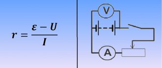
- Monitoring of output parameters is realized using an ammeter and a voltmeter.
Principle of operation
A circuit of transistors VT1 and VT2 controls the thyristor electrode. The current passes through VD2, which protects against return pulses. The optimal charging current is controlled by component R5. In our case, it should be equal to 10% of the battery capacity. To monitor the current regulator, this parameter must be installed in front of the connection terminals with an ammeter.
This circuit is powered by a transformer with an output voltage of 18 to 22 V. It is imperative to place the diode bridge, as well as the control thyristor, on the radiators to remove excess heat. The optimal radiator size should exceed 100cm2. When using diodes D242-D245, KD203, be sure to isolate them from the device body.
This thyristor charger circuit must be equipped with a fuse for the output voltage. Its parameters are selected according to your own needs. If you do not intend to use currents greater than 7 A, then a 7.3 A fuse will be sufficient.
Features of assembly and operation
Theristor testing circuit
The charger assembled according to the presented diagram can later be supplemented with automatic protective systems (against polarity reversal, short circuit, etc.). Particularly useful, in our case, will be the installation of a system for cutting off the current supply when charging the battery, which will protect it from overcharging and overheating.
It is advisable to equip other protective systems with LED indicators that indicate short circuits and other problems.
Monitor the output current carefully as it may vary due to line fluctuations.
Like similar thyristor phase-pulse regulators, a charger assembled according to the presented circuit interferes with radio reception, so it is advisable to provide an LC filter for the network.
Thyristor KU202N can be replaced with similar ones KU202V, KU 202G or KU202E. You can also use the more productive T-160 or T-250.
DIY thyristor charger
To assemble the presented circuit yourself, you will need a minimum of time and effort, along with low costs for components. Most of the components can be easily replaced with analogues. Some parts can be borrowed from failed electrical equipment. Before use, the components should be checked, thanks to this, a charger assembled even from used parts will work immediately after assembly.
Unlike models on the market, the performance of a self-assembled charger is maintained over a larger range. You can charge a car battery from -350C to 350C. This and the ability to regulate the output current, giving the battery a large amperage, allows in a short time to compensate the battery for a charge sufficient to turn the starter on the engine.
Thyristor chargers have a place in car enthusiasts' garages due to their ability to safely charge a car battery. The schematic diagram of this device allows you to assemble it yourself using products from the radio market. If knowledge is not enough, you can use the services of radio amateurs who, for a fee that is several times less than the cost of a store-bought charger, will be able to assemble the device for you according to the diagram provided to them.
The use of thyristor chargers is justified - restoration of battery functionality occurs much faster and more “correctly”. The optimal value of the charging current and voltage is maintained, so it is unlikely to harm the battery. After all, overvoltage can cause the electrolyte to boil away and destroy the lead plates. And all this leads to failure. But you need to remember that modern lead batteries can withstand no more than 60 full discharge and charge cycles.
Universal charger “Frog” for phones – review
A compact charging device called “Frog” has been serving people for many years. Its advantages lie in its compactness and versatility. Using it, you can charge the battery from a mobile phone of any model; you just need to correctly move the antennae of the device.
“Frog”, “Clothespin” for the phone is suitable for all types of mobile gadgets.
The device is made in China, has several indicators that show the start of the charge in red (second indicator), and when the charge is complete, the green indicator lights up (third light). The gadget is able to independently determine the polarity of the connected battery, so you don’t have to worry about whether it was installed correctly. “Zhabka” is only suitable for batteries with a capacity of no more than 2000 mAh at an alternating current of up to 200 mA. Charging on this device lasts more than 1.5 hours. You can buy a universal “Frog” charger both in online stores and at any radio kiosk.
General description of the charger circuit
Anyone can make thyristors if they have knowledge of electrical engineering. But in order to do all the work correctly, you need to have at least the simplest measuring device on hand - a multimeter.
It allows you to measure voltage, current, resistance, and check the performance of transistors. And there are the following functional blocks:
- A step-down device - in the simplest case, it is a regular transformer.
- The rectifier block consists of one, two or four semiconductor diodes. A bridge circuit is usually used because it produces almost pure direct current without ripple.
- A filter bank is one or more electrolytic capacitors. With their help, the entire alternating component in the output current is cut off.
- Voltage stabilization is carried out using special semiconductor elements - zener diodes.
- An ammeter and a voltmeter monitor current and voltage, respectively.
- The output current parameters are adjusted by a device assembled using transistors, a thyristor and a variable resistance.
Product design
The UZ-A device is a rectifier with a smooth current setting. From terminals 3, 6 of network transformer T1, the voltage is supplied to a 2[-half-wave controlled rectifier made using thyristors VS1 and VS2.
The rectified voltage is supplied to the battery through contacts X1 (“plus”) and X2 (“minus”). To control the amount of charge current, use the current indicator PA1.
To disconnect the charging circuit from the battery after 10.5 ± 1 hour, control the operation of the thyristors and set the required charging current, use a circuit assembled on transistors VT1 + VT11 and a DD1 microcircuit.
The main element is a transformer
There’s simply no way without it; it’s impossible to make a thyristor-controlled charger without using a transformer. The purpose of using a transformer is to reduce the voltage from 220 V to 18-20 V. This is exactly what is needed for normal operation of the charger. General design of the transformer:
- Magnetic core made of steel plates.
- The primary winding is connected to a 220 V AC source.
- The secondary winding is connected to the main board of the charger.
Some designs may use two secondary windings connected in series. But in the design discussed in the article, a transformer is used, which has one primary and the same number of secondary windings.
Precautionary measures
When using self-assembled devices, the following safety precautions should be observed:
- All devices, including the battery, must be on a fire-resistant surface.
- When using the manufactured device for the first time, it is necessary to ensure full control of all charging parameters. It is imperative to control the heating temperature of all charging elements and the battery; the electrolyte should not be allowed to boil. The voltage and current parameters are controlled by a tester. Primary monitoring will help determine the time it takes to fully charge the battery, which will be useful in the future.
Assembling a battery charger is easy even for a beginner. The main thing is to do everything carefully and follow safety measures, because you will have to deal with an open voltage of 220 volts.
Under normal operating conditions, the vehicle's electrical system is self-sufficient. We are talking about energy supply - a combination of a generator, a voltage regulator, and a battery works synchronously and ensures uninterrupted power supply to all systems.
This is in theory. In practice, car owners make amendments to this harmonious system. Or the equipment refuses to work in accordance with the established parameters.
- Operating a battery that has exhausted its service life. The battery does not hold a charge
- Irregular trips. Prolonged downtime of the car (especially during hibernation) leads to self-discharge of the battery
- The car is used for short trips, with frequent stopping and starting of the engine. The battery simply does not have time to recharge
- Connecting additional equipment increases the load on the battery. Often leads to increased self-discharge current when the engine is turned off
- Extremely low temperature accelerates self-discharge
- A faulty fuel system leads to increased load: the car does not start immediately, you have to turn the starter for a long time
- A faulty generator or voltage regulator prevents the battery from charging properly. This problem includes worn power wires and poor contact in the charging circuit.
- And finally, you forgot to turn off the headlights, lights or music in the car. To completely discharge the battery overnight in the garage, sometimes it is enough to close the door loosely. Interior lighting consumes quite a lot of energy.
Any of the above reasons leads to an unpleasant situation: you need to drive, but the battery is unable to crank the starter. The problem is solved by externally feeding the battery: that is, a charger.
The tab contains four proven and reliable car charger circuits from simple to the most complex. Choose any one and it will work.
Rough calculation of transformer windings
It is advisable to use a transformer with an existing primary winding in the design of a thyristor charger. But if there is no primary winding, you need to calculate it. To do this, it is enough to know the power of the device and the cross-sectional area of the magnetic circuit. It is advisable to use transformers with a power of over 50 W. If you know the cross-section of the magnetic circuit S (sq. cm), you can calculate the number of turns for every 1 V of voltage:
N = 50 / S (sq. cm).
To calculate the number of turns in the primary winding, you need to multiply 220 by N. The secondary winding is calculated in a similar way. But you need to take into account that in a household network the voltage can jump up to 250 V, so the transformer must withstand such changes.
Preparation and work procedure
Remove the power cord and contact clips from the niche.
Place the device firmly on the handle-stand.
Set the adjustment knob to the extreme left position.
Connect the contact clamps of the device to the terminals of the battery, observing the polarity:
- “+” clamp of the device to “+” battery;
- "-" clamp of the device to the "-" battery.
Connect the device to a 220 V AC mains voltage, and the “NETWORK” LED on the front panel will light up and, depending on the state of the electronic circuit, the LED may light up.
Press the button . At the same time, if after switching on the LED I was on, it will go out. Turn the adjustment knob to set the required charging current using the current indicator.
When charging a battery, the charge current may increase at the first moment, and then gradually decrease as it is charged, which is a sign of an increase in the emf of the battery. To improve the battery charging mode, after 6-8 hours the charging current will automatically decrease by 1.3 - 2.5 times.
After 10.5 hours (± 1 hour), the device automatically disconnects from the battery, and the LED on the front panel lights up.
Source: Khodasevich A. G., Khodasevich T. I., Chargers and starting-charging devices, Issue 2.
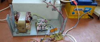
Guys, don’t kick too hard, please help me repair the Electronics UZS-12-6.3 charger. I have a little knowledge of electronics, but I can’t find a problem with this charger.
Screenshots of the appearance, diagram and reverse side of the board.
This charger was given to me in no longer working condition. I worked for a man for 10 years, but burned out. When I opened it, I immediately discovered that the secondary winding had burned out. I decided to change the transformer by removing it from another charger - Velvet. The transformer is the same - the secondary winding produces
36v, from the middle terminal of the secondary winding
When I plugged it into the network for the first time (without connecting it to the battery - according to the instructions, the charger starts charging only after connecting to the battery), I saw that the “Network” LED vd5 was not lit. I checked the fuses (3 pieces) of the network and thyristor protection. I turned it off and, out of sin, checked all the transients, diodes (soldered them out) - replaced a pair of KT-361 - there were EC breakdowns - replaced them with an analogue BC556. I checked the thyristors by unsoldering them from the circuit, applying 12v to the spacecraft and a 1.5v battery to the control electrode (CE) - everything is fine, they are working and the light came on when power was supplied to the CE. I rang without soldering all the resistors to the break (I didn’t visually detect any darkened or obviously burnt ones). I replaced all (4 pieces) of electrolytes - because I thought that they could well be bent from old age. Visually checked the tracks on the board - everything is in order.
Read also: Press rolling machine for rotary drawing of metal
Of course, I didn’t find the “Network” LED AL307BM and connected the LED to illuminate the instrument panel in the car.
I plugged the charger into the network - the “Network” LED lit up as expected, connected the charger to the battery, but charging did not start. It does not respond to the “Control” button, does not respond to switching charging modes.
Silent as a fish on ice
When connected to the battery terminal, a small spark jumps and the ammeter tries to deflect the needle, but this happens for a split second.
I checked all the transistors again - they were in good condition.
Please direct me on the right path to start diagnostics step by step to find the fault.
The specified product, manufactured in 2000, was brought in for repair; the stated fault was low battery charge current.
I turn it on and check - indeed, in the “MAX” position of the current regulator knob, the output current according to the built-in ammeter and the control ammeter connected in series with the load is only 3 amperes. The current is adjustable from 0 to 3 amperes, the adjustment is smooth. Let's look at the circuit diagram of the memory
The construction resistor R15 should determine the upper limit for adjusting the charge current. You should try to adjust the position of the moving contact of this resistor. Open the charger case and look at the board
and resistor R15 has no moving contact at all! That is, the entire conductive path of the resistor is constantly connected to the circuit. How could the manufacturer solder an obviously unusable component into the board? It seems that the enterprise does not belong to the VOS structure, and sighted installers should have rejected such a resistor. Instead of this unfortunate trimming resistor, we solder in a regular variable resistor with a resistance of 3.3 kOhm, adjust the upper limit for adjusting the charge current to 6 amperes, measure the resistance of part of the variable resistor, and solder into the board instead of R15 a constant resistor of a value close to the measured value. Interestingly, I was able to achieve 6 amperes of charging current only with a resistance of R15 = 0. So, instead of R15, we soldered a jumper. These are the quirks of renovation. Yes, by the way, both KU202G thyristors are operational, and the output current has a pulse frequency of 100 Hz. This leads to the possible assumptions of some: “Are both SCRs working for you or just one?”
Winding and assembly of the transformer
Before you start winding, you need to calculate the diameter of the wire that you will need to use. To do this you need to use a simple formula:
d = 0.02×√I (windings).
The wire cross-section is measured in millimeters, the winding current is measured in milliamps. If you need to charge with a current of 6 A, then substitute the value of 6000 mA under the root.
Having calculated all the parameters of the transformer, you begin winding. Lay the coil evenly to the coil so that the winding fits in the window. Fix the beginning and end - it is advisable to solder them to free contacts (if any). Once the winding is ready, you can assemble the transformer steel plates. Be sure to coat the wires with varnish after winding is completed, this will help get rid of the humming noise during operation. The core plates can also be treated with an adhesive solution after assembly.
PCB manufacturing
To make a printed circuit board on a thyristor yourself, you need to have the following materials and tools:
- Acid for cleaning the surface of foil material.
- Solder and tin.
- Foil textolite (getinax is more difficult to obtain).
- Small drill and drill bits 1-1.5 mm.
- Ferric chloride. It is much better to use this reagent, since with its help excess copper is removed much faster.
- Marker.
- Laser printer.
- Iron.
Before starting installation, you need to draw the tracks. It is best to do this on a computer, then print the drawing on a printer (necessarily laser).
Printing should be done on a sheet from any glossy magazine. The drawing is translated very simply - the sheet is heated with a hot iron (without fanaticism) for several minutes, then cools down for a while. But you can also draw paths by hand with a marker, and then place the PCB in the solution for a few minutes.
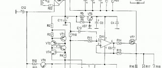
Purpose of memory elements
The device is based on a phase-pulse regulator on a thyristor. There are no scarce components in it, so if you install serviceable parts, the entire circuit will be able to work without adjustment. The design contains the following elements:
- Diodes VD1-VD4 are a bridge rectifier. They are designed to convert alternating current into direct current.
- The control unit is assembled on unijunction transistors VT1 and VT2.
- The charging time of capacitor C2 can be adjusted by variable resistance R1. If its rotor is shifted to the extreme right position, the charging current will be highest.
- VD5 is a diode designed to protect the thyristor control circuit from reverse voltage that occurs when turned on.
This scheme has one big drawback - large fluctuations in the charging current if the network voltage is unstable. But this is not a hindrance if a voltage stabilizer is used in the house. You can assemble a charger using two thyristors - it will be more stable, but it will be more difficult to implement this design.
general characteristics
To properly maintain the battery and extend its service life, recharging is required when the voltage at the terminals drops below 11.2 V. At this voltage, the engine will most likely start, but if parked for a long time in winter, this will lead to sulfation of the plates and, as a result, a decrease in capacity batteries. When parked for a long time in winter, it is necessary to regularly monitor the voltage at the battery terminals. It should be 12 V. It is best to remove the battery and take it to a warm place, while not forgetting to monitor the charge level .
The battery is charged using constant or pulsed current. When using a constant voltage power supply, the current for proper charging should be one tenth of the battery capacity . If the battery capacity is 50 Ah, then a current of 5 amperes is required for charging.
To extend the battery life, battery plate desulfation techniques are used.
The battery is discharged to a voltage of less than five volts by repeated consumption of a large current of short duration. An example of such consumption is starting a starter .
After this, a slow full charge is carried out with a small current within one ampere. Repeat the process 8-9 times. The desulfation method takes a long time, but according to all studies it gives good results. It must be remembered that when charging, it is important not to overcharge the battery. The charge is carried out to a voltage of 12.7-13.3 volts and depends on the battery model. The maximum charge is indicated in the documentation for the battery, which can always be found on the Internet.
Overcharging causes boiling , increases the density of the electrolyte and, as a result, destruction of the plates. Factory charging devices have charge monitoring and subsequent shutdown systems. to assemble such systems yourself without sufficient knowledge in electronics.
Installation of elements on a printed circuit board
It is advisable to mount the diodes and thyristor on separate radiators, and be sure to isolate them from the housing. All other elements are installed on the printed circuit board.
It is undesirable to use wall-mounted installation - it looks too unsightly and is dangerous. To place elements on the board, you need:
- Drill holes for the legs with a thin drill.
- Tin all printed tracks.
- Cover the tracks with a thin layer of tin, this will ensure reliable installation.
- Install all elements and solder them.
After installation is complete, you can coat the tracks with epoxy resin or varnish. But before that, be sure to connect the transformer and the wires that go to the battery.
Final assembly of the device
After installing the charger on the KU202N thyristor, you need to find a suitable housing for it. If there is nothing suitable, make it yourself. You can use thin metal or even plywood. Place the transformer and radiators with diodes and thyristor in a convenient place. They need to be well cooled. For this purpose, you can install a cooler in the rear wall.
You can even install a circuit breaker instead of a fuse (if the dimensions of the device allow). On the front panel you need to place an ammeter and a variable resistor. Having assembled all the elements, you begin testing the device and its operation.
Compact thyristor charger
Figure 1 shows a diagram of a simple charger for a car battery.
Fig. 1 When a certain voltage value is reached (set by the circuit R2, V1, V2), the charger on the thyristor disconnects it from the battery. The reference voltage on the battery is compared at each positive half-cycle while the thyristor is closed. When the battery is discharged, the thyristor opens at the moments of each positive half-cycle with some delay, but only as the battery is close to being fully charged, the thyristor will open with a greater delay and when a certain value is reached, when the battery is fully charged, the thyristor will stop opening. The voltage comparison takes place in the thyristor control electrode circuit. The voltage at the thyristor output depends on its parameters, so it is possible to select a thyristor if the voltage of 13.5V turns out to be slightly underestimated. Any transformer for a voltage in the secondary winding of 20V based on the value of the charging current.
Bornovolokov E.P., Florov V.V. Amateur radio circuits - 3rd edition, revised. and additional - K.: Technology, 1985
Automatic charger
Figure 2 shows a diagram of an automatic charger that allows you to charge a car battery when discharged and stop charging when the battery is fully charged. It is advisable to use such a device for batteries that are stored for a long time.
Fig.2
Switching to charging mode is done by measuring the voltage at the battery terminals. Charging begins when the voltage at the battery terminals drops below 11.5 V and stops when it reaches 14 V.
The op amp in the circuit serves as a precision voltage comparator that monitors the battery voltage level. Its inverting input receives a reference voltage of 1.8 V, and a battery voltage of about 2 V is supplied to the non-inverting input through a divider (when the battery is fully charged). In this case, the relay is disabled because the op-amp output is at a high voltage level. When the voltage drops at the battery terminals, the voltage at the non-inverting input of the op-amp becomes 1.8 V, the comparator switches, this leads to the relay turning on, and the battery begins to charge.
After assembling the charger, it must be adjusted:
1. Discharge the battery to a voltage of 11.5 V 2. Connect the charger to the battery 3. Adjust R6 until the relay is activated 4. When charging the battery, measure the voltage at its terminals, when it reaches 14 V, adjust the potentiometer R5 until the relay turns off If necessary repeat the setup process
Charger for LM317
Fig.3
Based on the LM317 stabilizer, you can make a simple and effective charger. The proposed device is designed for charging 12 V batteries. The maximum charging current is 1.5A. The charging current can be adjusted using potentiometer R5. As the battery charges, the charger reduces the charging current. The LM317 stabilizer must be installed on the radiator.
Charge current indication unit
If your car battery charger does not have an ammeter, it is difficult to ensure reliable charging. There may be deterioration (loss) of the contact on the batteries, which is quite difficult to detect. Instead of an ammeter, a simple indicator is proposed in Fig. 4. It is connected to the gap in the “positive” wire from the charger to the battery.
Fig.4
The circuit is a transistor switch VT1, which turns on the LED HL1 when charging current flows through R1. In this case, the voltage drop across resistor R1 (more than 0.6V) is sufficient to open transistor VT1 to ignite HL1. For a specific battery, the R1 rating is selected so that the LED lights up at the required charging current. By the brightness of its glow, you can approximately estimate the charging current. Resistor R1 is a wire-wound resistor, made from 6…12 turns of winding wire with a diameter of 1 mm. You can use wire with high resistivity (nichrome) or an industrial resistor, for example, PEVR-10.
Charger with car voltage regulator
A simple charger, shown in Fig. 5, will serve to charge the battery and keep it in working condition for a long time.
Fig.5
From the secondary winding of transformer T1, the current in which is limited by being connected in series with the primary winding of the ballast capacitor (C1 or C1 + C2), the current is supplied to the diode-thyristor bridge, the load of which is the battery (GB 1). An automotive 14 V generator voltage regulator (GVR) of any type, intended for generators with a grounded brush, is used as a regulating element. Thus, the battery maintains a voltage of 14 V at a charging current determined by the capacitance of capacitor C2, which is approximately calculated by the formula:
3200. I z. U 2
C (uF) = ————— ——— ,
U 1 2
where Iz is the charging current (A), U 2 is the voltage of the secondary winding when the transformer is “normally” turned on (V), U 1 is the mains voltage.
The device requires virtually no setup. You may need to check the capacitance of the capacitor by monitoring the current with an ammeter. In this case, it is necessary to short-circuit terminals 15 and 67 (B, V and Sh).
From railway (RL 5-99)
Reversing attachment for the charger
This attachment, the circuit of which is shown in Fig. 6, is made on a powerful composite transistor and is intended for charging a car battery with a voltage of 12V alternating asymmetric current. This ensures automatic training of the battery, which reduces its tendency to sulfate and extends its service life. The set-top box can work together with almost any full-wave pulse charger that provides the required charging current.
Fig.6
When the output of the set-top box is connected to the battery (the charger is not connected), when capacitor C1 is still discharged, the initial charging current of the capacitor begins to flow through resistor R 1, the emitter junction of transistor VT 1 and resistor R 2. Transistor VT 1 opens, and a significant battery discharge current, quickly charging capacitor C1. With an increase in the voltage on the capacitor, the battery discharge current decreases to almost zero.
After connecting the charger to the input of the set-top box, a battery charging current appears, as well as a small current through resistor R 1 and diode VD 1. In this case, transistor VT 1 is closed, since the voltage drop across the open diode VD 1 is not enough to open the transistor. Diode VD 3 is also closed, since the reverse voltage of the charging capacitor C1 is applied to it through diode VD 2.
At the beginning of the half-cycle, the output voltage of the charger is added to the voltage on the capacitor, and the battery is charged through the diode VD 2, which leads to the return of the energy accumulated by the capacitor to the battery. Next, the capacitor is completely discharged and diode VD 3 opens, through which the battery now continues to charge. A decrease in the output voltage of the charger at the end of the half-cycle to the level of the battery EMF and below leads to a change in the polarity of the voltage on the diode VD 3, closing it and stopping the charging current.
In this case, transistor VT 1 opens again and a new impulse occurs in discharging the battery and charging the capacitor. With the beginning of a new half-cycle of the charger's output voltage, the next battery charging cycle begins.
The amplitude and duration of the battery discharge pulse depend on the values of resistor R2 and capacitor C1. They are selected according to the recommendations.
The transistor and diodes are placed on separate heat sinks with an area of at least 120 cm 2 each.
In addition to the KT827A transistor indicated in the diagram, you can use KT827B, KT827V. The set-top box can use transistors KT825G - KT825E and diodes KD206A, but the polarity of the diodes, capacitor, as well as the input and output terminals of the set-top box must be reversed.
Fomin.V
Nizhny Novgorod
Simple automatic charger
A typical charger for charging starter batteries consists of a transformer, the winding of which has taps, a diode half-wave rectifier and an ammeter that measures the charging current. Such a charger cannot control the charging process and cannot restore sulfated batteries.
Fig.7
If at the output of such a charger you turn on a node, the diagram of which is shown in Fig. 7, then the device will become automatic and learn to restore the batteries with a training current.
When the battery is connected, the thyristor opens only on positive half-cycles of the pulsating voltage. On the negative side (when the rectifier diode of the charger is closed), the thyristor is closed and a training discharge of the battery occurs through resistor R 3.
At the beginning of each half-cycle, even before the thyristor opens, the voltage on the battery is measured. If this is the voltage of a fully charged battery (13.5 V), then the zener diode opens and prevents the thyristor from opening.
As the battery charges, the thyristor opens closer to the top of the pulsating voltage. The closing of the thyristor occurs at the decline of the half-wave of the pulsating voltage, when this voltage becomes lower than the voltage on the battery.
Karavkin V.
Literature:
Vasiliev V.
"Charger"
and. Radio No. 3 1976
Car battery recharging device
If the car sits idle for a long time, its battery gradually discharges. This is especially felt when storing a car in unheated garages in the winter - at subzero temperatures. Starting the engine involves searching for a starting device from familiar car enthusiasts or trying to get a charged battery from them for temporary use. A car battery recharger can help avoid this problem. The simplicity of the circuit and the absence of scarce radio components make it accessible for repetition.
It is well known that all chemical current sources are subject to self-discharge. The degree of self-discharge depends on a number of reasons. The reasons due to the design features of the batteries are not discussed in this article - motorists have to use the batteries that are on their vehicles. The technological (for cars) reason for battery discharge is due to the storage conditions of the battery. Both the service life of the battery and the degree of its readiness to work in the electrical equipment of the car will depend on this.
The self-discharge current of car batteries largely depends on the “age” of the battery. Approximately, we can assume that the self-discharge current of a battery when stored in an unheated room or outdoors is up to 180 mA. Approximately this battery charging current will ensure its constant readiness for operation.
In the circuit (Fig. 8), low-power transformer TR 1 reduces the voltage of 220 V to approximately 12 V.
Fig.8
The alternating voltage is rectified by bridge rectifier D 1 and supplied through resistor R 3 to the “OUT” output. It is possible to use the XR 1 car plug, which can be inserted into the car's cigarette lighter socket. When power is applied to the circuit, the green LED D 2 lights up.
When charging current flows to the car battery, a voltage drop is created across resistor R 3. When applied to the base of transistor T1 through resistor R 4, this voltage causes saturation of the transistor and LED D 3 (RED) lights up.
Yakovlev E.L.
Uzhgorod
(“Radioamator” No. 12, 2009)
Battery charger
In the absence of a full-fledged charger, a fairly simple rectifier can be made according to the simple circuit in Fig. 9.
Fig.9
It cannot replace a full-fledged charger, since the charging current is only 0.4 ... 0.5 A, but it is quite suitable for, for example, bringing the battery to the working state that was lost in 2 ... 3 days during the months of winter inactivity. The rectifier is assembled on four silicon diodes. A 220V lamp with a power of 70...100 W is connected in series with them, limiting the charging current. The circuit can use diodes having a maximum permissible reverse voltage of at least 400 V and an average rectifying current of at least 0.4 A. Diodes D7Zh, D226, D226D, D237B, D231, D231B, D232 or others with similar characteristics are suitable.
When working with the rectifier, care should be taken, since all its parts are connected directly to the electrical network through the lamp and therefore touching them is dangerous. If the rectifier is connected to the network, then you should not even touch the battery case, as it may be covered with a thin film of electrolyte - a conductor of electric current. If it is necessary to measure the voltage or density of the electrolyte in the battery, the rectifier must be disconnected from the network.
Gornushkin Yu.
“Practical advice for a car owner”
Simple charger
The circuit is a simple transformerless power supply that produces a constant voltage of 14.4 V, with a current of up to 0.4 A. (Fig. 10)
Fig.10
The design is simple and is used to recharge a battery that has been stored for a long time.
As practice shows, restoration requires a small current, about 0.1-0.3 A (for 6ST-55). If the stored battery is periodically, approximately once a month, recharged for 2-3 days, then you can be sure that it will be ready for use at any time, even after several years of such storage (practically tested).
The source is built according to the circuit of a parametric stabilizer with capacitive ballast resistance. The voltage from the mains is supplied to the bridge rectifier VD 1 ... VD 4 through capacitor C 1. At the output of the rectifier, a 14.4 V zener diode VD 5 is switched on. Capacitor C 1 dampens excess voltage and limits the current to no more than 0.4 A. Capacitor C 2 smoothes out the ripples of the rectified voltage. The battery is connected in parallel with VD 5.
The device works as follows. When the battery self-discharges to a voltage below 14.4 V, its “soft” charging begins with a weak current, and the value of this current is inversely dependent on the voltage on the battery. But in any case (even with a short circuit) it does not exceed 0.4 A. When charging the battery to a voltage of 14.4 V, the charging current stops altogether.
The device uses: capacitor C 1 - paper BMT or any non-polar one for 3...5 μF and a voltage of at least 300 V, C2 - K50-3 or any electrolytic for 100...500 μF, for a voltage not lower than 25 V; rectifier diodes VD 1... VD 4 - D226, KD105, KD208, KD209, etc.; Zener diode D815E or others for a voltage of 14 -14.5 V at a current of not less than 0.7 A. It is advisable to mount the zener diode on a heat sink plate.
When operating devices of this type, you must follow safety rules when working with electrical installations.
Thyristor regulator in the charger.
Technical data
- Supply voltage – 220 ± 22 V;
- Mains frequency – 50 ± 05 Hz;
- Charging current setting range – 0.5 – 6.3 A;
- Automatic disconnection from the battery after -10.5 ± 1 h;
- Power consumption, no more than -145 W;
- Alternating voltage for powering a portable car lamp (12 or 36±2V).
On the front panel there are:
- “NETWORK” LED, signaling that the device is connected to the network;
- current indicator for monitoring the charge current;
- button to turn the charger into charge mode;
- knob for setting the charge current;
- LED indicating the end of the charge cycle.
There is a radiator on the back wall of the charger to cool the rectifier. The radiator has a socket for powering a portable lamp (12 or 36 V), an electric soldering iron, etc., and a fuse.
At the bottom of the body of the device there is a niche into which the power cord and cables with contact clamps “+” and “-” are placed for connecting the charger to the corresponding battery terminals.
Rice. 1. Appearance of the automatic charging device “Electronics”.