Disassembling the power supply and troubleshooting
The repair began with disassembly and checking the fuse. When checking, the multimeter showed infinity, which indicates a broken fuse.
Power supply after disassembly. Location of the fuse on the board.
Often, a blown fuse is only a consequence, and the cause of the breakdown has yet to be found. For these purposes, I used a 100W incandescent lamp, replacing it with a fuse. In normal condition, it should light up (at the moment of charging the network capacitors), and then go out. In standby mode, when the power supply consumption is low, the lamp may light up a little and then go out. This behavior will be repeated cyclically.
If the lamp lights up brightly, this may indicate that there is a short circuit in the primary circuit, or there is an excessive load at the outputs of the power supply.
Having thrown the lamp, it lit up brightly.
The incandescent lamp lights up brightly when connected.
To check whether the power supply produces any voltage, I again connected the tester to its output. As a result, it showed the presence of output voltages.
Output voltages from the power supply
This was a good sign; all that remained was to determine the cause of the increased current consumption. At first, I thought about a diode bridge, but at the very beginning of the circuit, after looking a little closer, I saw a burnt varistor. Its malfunction was difficult to notice, since it was covered with a thermal insulating tube, after removing which everything fell into place. The varistor was burnt out and clearly out of order.
Varistor after desoldering from the board
After removing the thermal insulation tube everything fell into place
Voltage drop across the varistor. Ideally, the tester should not show anything.
Operating principle, designation on the diagram, application options
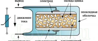
Externally, a varistor is very similar to a capacitor, but its internal structure, as can be seen from Figure 3, is completely different.
Figure 3. Varistor design (1) and its designation on the diagrams (2)
Designations:
- A – two metal electrodes in the shape of a disk;
- B – inclusions of zinc oxide (crystal size not observed);
- C – semiconductor shell made on the basis of synthetic hardeners (epoxies);
- D – ceramic insulator;
- E – conclusions.
Read also: Vertical drilling machine 2a135 price
In addition to the design, Figure 3 shows the designation of the element on the circuit diagrams (2).
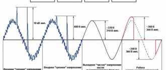
The content of zinc oxide in the ceramic insulating layer determines the response threshold of the varistor; as soon as the voltage becomes higher than permissible, the resistance decreases sharply and the current passing through the semiconductor increases. The thermal energy generated as a result of this process is dissipated in the air.
This principle of operation allows you to prevent failure of electronic devices due to a short-term voltage drop. A long pulse will cause overheating and destruction of the varistor, but this process takes time. Although it is measured in fractions of a second, in most cases this is enough to trip the fuse.
That is why, after replacing the fuse, it is necessary to check the varistor (external inspection and testing with a multimeter). Otherwise, the next voltage drop will most likely lead to the destruction of the components of the electronic device.
Information about varistors
For beginners, I’ll tell you a little about varistors . A varistor is a type of resistor that changes its resistance depending on the voltage that is applied to it.
I'll show you with an example.
Diagram of varistor operation at normal voltage
Let's assume that a varistor is installed in the circuit, for example, which starts to operate at 270 volts. While the voltage is below this value, the resistance of the varistor is too high, and the voltage freely powers the board, bypassing the varistor.
Operating principle
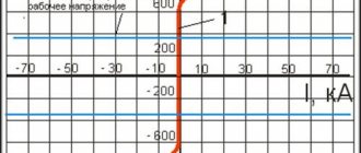
A varistor is a semiconductor device with a symmetrical nonlinear current-voltage characteristic. Based on its shape, we can conclude that the varistor operates in both alternating and direct current. Let's look at it in more detail.
In normal condition, the current through the varistor is extremely small; it is called leakage current. It can be considered as a dielectric component with a certain electrical capacitance and can be said to not allow current to pass through. But, at a certain voltage (in the picture it is + - 60 Volts) it begins to pass current.
In other words, the principle of operation of a varistor in protective circuits resembles a spark gap, only an arc discharge does not occur in a semiconductor device, but its internal resistance changes. As the resistance decreases, the current increases from a few microamps to hundreds or thousands of amperes.
Conventional graphical representation of a varistor in diagrams:
The designation of the element on the diagrams resembles a regular resistor, but crossed out diagonally by a line on which the letter U can be printed. To find this element on the board or in the circuit, pay attention to the labels; most often they are designated as RU or VA.
Varistor appearance:
A varistor is installed in parallel with the circuit to protect it. Therefore, when the voltage pulse of the protected circuit occurs, the energy does not enter the device, but is dissipated in the form of heat on the varistor. If the pulse energy is too high, the varistor will burn out. But the concept will burn out, there are two options for development. Either the varistor will simply break into pieces, or its crystal will be destroyed and the electrodes will be short-circuited. This will cause the tracks and conductors to burn out, or the housing elements and other parts will catch fire.
Read also: DIY mechanical crafts
To avoid this, a fuse is installed in front of the varistor in series with the entire circuit on the signal or supply wire. Then, in the event of a strong voltage pulse and long-term operation or burnout of the varistor, the fuse will also burn, breaking the circuit.
In short, what is such a component for? Its properties make it possible to protect the electrical circuit from harmful surges of voltage that can occur both on information lines and on electrical lines, for example, when switching powerful electrical appliances. We will discuss this issue a little below.
Result of repair
Having replaced the fuse and installed a varistor from a donor, the power supply was assembled and tested.
If, when repairing an air conditioner, you find a blown fuse on the circuit board, do not rush to change it immediately; first find out the reason why it burned out.
Most likely this happened due to power surges in the network.
When measuring the supply voltage in the network, it constantly fluctuates, and not always within safe limits for air conditioners.
Plus, the network always contains short pulses with voltages of several kilovolts. This happens due to the constant switching off and on of inductive and capacitive loads (electric motors, transformers, etc.), as well as due to atmospheric electricity.
Air conditioners, like any other electronic equipment, are protected in this case by varistors. More precisely, the electronic filling of the air conditioner - the control board.
Operating principle of a varistor
Essentially, a varistor is a nonlinear semiconductor resistor, the conductivity of which depends on the voltage applied to it. At normal voltage, the varistor passes a negligibly small current through itself, and at a certain threshold voltage it opens and passes the entire current through itself. Thus, it filters short pulses; if the pulse is longer, and the current flowing through the varistor exceeds the rated current of the fuse, it will simply burn out, de-energizing and protecting the load.
Varistor marking
There are a huge number of varistors from different manufacturers, with different threshold operating voltages and designed for different currents. You can find out which varistor was installed by its marking. For example, marking varistors CNR :
CNR-07D390K , where:
- CNR-series, full name CeNtRa metal oxide varistors
- 07- diameter 7mm
- D – disk
- 390 – actuation voltage, calculated by multiplying the first two digits by 10 to the power equal to the third digit, that is, 39 multiplied by 10 to the zero power, you get 39 V, 271-270 V, etc.
- K – tolerance 10%, that is, the voltage spread can fluctuate from the nominal by 10% in any direction.
Information about varistors
For beginners, I’ll tell you a little about varistors . A varistor is a type of resistor that changes its resistance depending on the voltage that is applied to it.
I'll show you with an example.
Diagram of varistor operation at normal voltage
Let's assume that a varistor is installed in the circuit, for example, which starts to operate at 270 volts. While the voltage is below this value, the resistance of the varistor is too high, and the voltage freely powers the board, bypassing the varistor.
Diagram of how a varistor works when the voltage is too high
When about 300 volts are supplied, the resistance of the varistor sharply decreases, after which it begins to take on the entire load. At the same time, the overvoltage does not reach the circuit, which is where the effect of protecting the board is manifested.
When the varistor trips, the entire load is transferred to the fuse, after which it burns out and saves the board from further overloads.
This is what happened in my example. The varistor burned out, which saved the Pttanium block board. The varistor rating in my board was TVR10431. This is a varistor whose classification voltage is 430 volts. According to the datasheet, this varistor starts to operate at a voltage of 270 volts AC.
Designation, parameters and application of varistors
Anyone who has come across electronic equipment has probably noticed that the name of most electronic components ends with “store”. Resistor, transistor, thyristor, stabistor.
Let's look at another component of electronic circuits. It is called a varistor and is a resistor whose resistance varies depending on the amount of applied voltage.
Varistor (Variable Resistor) is translated as variable resistance. And this is how a varistor is indicated on circuit diagrams.
The letter U next to a slash indicates that the resistance of an electronic component depends on voltage. On diagrams, a varistor is usually marked with two letters RU , and after them is placed the serial number of the varistor in the diagram (1, 2, 3.).
A varistor is a semiconductor device made from silicon carbide (SiC) or zinc oxide (ZnO) powder by pressing. The varistor has a symmetrical and nonlinear current-voltage characteristic, so it can be used in DC and AC circuits. Varistors have a quality that is extremely useful for electrical circuits. They are capable of dramatically changing their resistance when the voltage exceeds a certain operating threshold.
In the event of a voltage pulse capable of damaging an electronic device, the varistor almost instantly changes its resistance from hundreds of megohms to tens of ohms, that is, it short-circuits the power circuit, so a regular fuse is always placed in front of the varistor.
Previously, gas-filled arresters were installed for such protective purposes, but their performance and reliability cannot be compared with the parameters of varistors. For example, a disk varistor without leads and soldered directly into a printed circuit board has a response time not exceeding several nanoseconds.
The varistor is connected in parallel to the power circuit. In the absence of dangerous voltage pulses, the current flowing through it is small and the varistor does not affect the operation of the circuit, since it is essentially a dielectric.
If an overvoltage pulse occurs, the varistor, due to the nonlinearity of the characteristic, reduces its resistance to almost zero. The load is shunted and the absorbed energy is dissipated as heat. A varistor does not have inertia, so after “cutting off” the pulse, it instantly acquires a very high resistance again.
If the overvoltage pulse was too large and powerful, then the varistor fails. Sometimes its body cracks, or even splits into several parts.
It happens that a varistor is very helpful in case of problems in the electrical network, as it receives a high-voltage pulse and contributes to a rapid break in the circuit. In this case, the main part of the circuit remains unharmed. The photo shows the power supply from the projector, which failed after a power surge in the 220V power supply.
After replacing the fuse, the projector's operation was fully restored. No complex repairs were required other than replacing the fuse and the varistor itself. This is how one small detail can save an expensive device.
Varistor parameters.
Main parameters of varistors:
Varistor classification voltage (Varistor Voltage). This is the voltage value at which a current of 1 mA flows through the varistor. This parameter is not operational and is rather conditional. When selecting a varistor, you should pay attention to the parameters that will be discussed below;
Maximum Allowable Voltage - ACrms. For varistors, the AC voltage is specified as the root mean square (rms) voltage. This is the magnitude of the alternating voltage at which the varistor “triggers” and begins to pass current through itself, performing its protective functions;
Maximum Allowable Voltage - DC. Same as the maximum permissible alternating voltage but for direct current. As a rule, the value of this parameter is greater than for alternating current. Also indicated in volts (V);
Maximum Clamping Voltage. This is the maximum voltage that the varistor can withstand without damage. As a rule, it is specified for a specific amount of current flowing through the varistor. If the limiting voltage is exceeded, the varistor fails. In this case, the varistor housing cracks in two or even falls into pieces.
Maximum absorbed energy in joules (J). This is the value of the maximum pulse energy that a varistor can dissipate in the form of heat without the threat of destruction of the varistor itself;
Response time is the time during which the varistor transitions from a high-resistance state to a low-resistance state when the maximum permissible voltage is exceeded. For widely used varistors, this value is several tens of nanoseconds (ns). For example, 25 ns.
Permissible deviation (Varistor Voltage Tolerance) – permissible deviation of the varistor qualification voltage. Indicated as a percentage - %. Can be ±5%, ±10%, ±20%, etc. In the marking of imported varistors, the tolerance value is encoded in the varistor marking with a letter. For example, for Joyin varistors the following designation is accepted: K – ±10%, L – ±15%, M – ±20%, P – ±25%. Thus, for a varistor type JVR-07N391 K , the deviation is no more than ±10%.
When selecting varistors for electronic circuits, it is better to refer to the datasheet for a specific varistor. This would be a more reasonable solution, since only the value of the qualification voltage is applied to the housing of imported varistors, by which it is quite difficult to judge the parameters of the protective element.
Application of varistors.
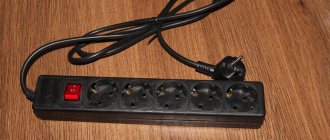
For a regular 220 volt network, protective varistors with an operating voltage of 275 - 420 volts are installed. Here is an example of a reliably protected surge protector.
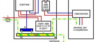
This surge protector is protected by three varistors. That is, the penetration of a pulse is reliably blocked not only through the phase circuit, but also through the zero circuit. Varistor RU1 stands between the phase and the neutral conductor. It provides basic protection. The other two RU2 and RU3 are connected between phase and ground and between zero and ground. Very often there is a situation when on an entire street all the electronic household equipment of all users is out of order. There were even television programs about such cases, when thousands of people could not figure out who to file a complaint against in court.
Read also: Make your own loom for rugs
And the whole point is that on the power supply line that supplies, say, a street or a microdistrict, instead of phase and zero, a phase went along both wires. This is almost certain death for unprotected household equipment. That is, between wires N and PE, if everything is normal, there should be no voltage. If a phase appears on wire N, the varistor RU2 will safely bypass the protected unit. This is one example of the use of varistors in power circuits of consumer electronic equipment.
Miniature multilayer varistors have long been used in mobile phone circuits to protect them from static electricity. Varistors are also used to reliably protect computer connectors and microprocessor pins from the same static. Varistors are widely used in automotive electronics and telecommunications equipment.
Varistors can be found in the input circuits of power supplies. Here is a photo of the varistor 391KD14 on the board of the redundant power supply.
And here the FNR-14K391 varistor is installed in the circuit of the Granit security device to protect its power supply from voltage surges in the 220V power supply.
You can also find a varistor on electronic ballast boards for fluorescent lamps. The photo shows a MYG-10K471 varistor installed in an electronic ballast circuit for four linear fluorescent lamps. On the board it is designated as RU.
Varistors for protecting consumer electronics are usually available in the form of a disk with two terminals. The larger the diameter of the disk, the more powerful the voltage pulse the varistor can absorb. The pulse power or energy that a varistor can “extinguish” is usually measured in joules (J).
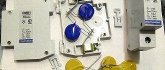
Here, for example, are several varistors. The value of the varistor diameter in millimeters, as a rule, is entered into the marking of the varistor itself, for example, JVR- 07 N391K (diameter - 7 mm).
The diameter of the largest varistor type MYG-14K391, shown in the photograph, is 14 mm. (
70 J), a slightly smaller varistor MYG-10K471 - 10 mm. (
45 J), and the small JVR-07N391K – 7 mm. (
The value of absorption energy in joules (J) is indicated in parentheses. As you can see, the varistor has the largest diameter of 14 mm. is capable of extinguishing the energy of a dangerous pulse of 70 joules, while the smallest varistor has a diameter of 7 mm. capable of extinguishing only 30 joules. Thus, by the diameter of the varistor one can indirectly judge its maximum absorption energy. It is clear that it is preferable to install varistors designed for high absorption energy in electronic circuits. It is also recommended to install two identical varistors in the circuit, connected in parallel.
There are also varistors for SMD installation. In appearance, they resemble SMD diodes and therefore are quite difficult to distinguish.
Domestic varistors include products of the brands CH2-1A, CH1-2-1, VR-4V, etc.
Of course, varistors have disadvantages, but they are not so significant compared to gas-discharge devices. First of all, varistors have quite a lot of noise at low frequencies, and also change their parameters over time and under the influence of temperature.
It is worth noting that among the protective components, in addition to the varistor, there is another electronic component - a suppressor. This is the so-called protective diode or transil. In terms of its functions (but not its design!) it is somewhat similar to a varistor, but has greater speed and, as a rule, is used in low-voltage circuits.
In addition to low-power varistors, which are used to protect household equipment, the industry produces very powerful varistors for high voltages and currents. They are used in transformer substations and are always included in lightning protection systems.
When installing varistors in home-made structures, it should be borne in mind that sometimes, when critical conditions arise, varistors can “explode” and in order to protect the installation and other radio-electronic components from the consequences of such an “explosion,” they try to place them in protective shields. If we compare varistors made of silicon carbide and zinc oxide, then, according to experts, the latter are preferable.
Not a single electrical network is immune from voltage surges; there are many reasons that cause this phenomenon, ranging from overload to phase imbalance. Such throws can damage household appliances, which is why almost all modern electronic devices have protection. If, after the next surge in the power supply of any device, a fuse has burned out, after replacing it, do not rush to turn on the equipment. Just in case, check the varistor for serviceability with a tester or multimeter.
Before proceeding to testing, we recommend that you familiarize yourself with a brief description of the varistor, its operating features and characteristics. This information may be useful when searching for an analogue to replace a failed element.
Characteristics
A varistor is a semiconductor resistor with a nonlinear current-voltage characteristic; its graph is shown in Figure 2.
Rice. 2. Typical current-voltage characteristics: A – varistor, B – conventional resistor
As can be seen from the graph, when the voltage across the semiconductor reaches a threshold value, the current increases sharply, which is caused by a decrease in resistance. This characteristic allows the varistor to be used as protection against short-term voltage surges.
