A varistor is a passive, two-terminal, solid-state semiconductor device that is used to provide protection to electrical and electronic circuits. Unlike a fuse or circuit breaker, which provide overcurrent protection, a varistor provides overvoltage protection by regulating the voltage, similar to a zener diode.
The word “Varistor” is an abbreviation and combination of the words “ Varistor - variable resistor”, a resistor having variable resistance, which in turn describes its operating mode. Its literal translation from English (Variable Resistor) can be a little misleading - comparing it with a potentiometer or rheostat.
Board holder
Material: ABS + metal, PCB clamp size (max): 20X14cm...
More details
But, unlike a potentiometer, the resistance of which can be changed manually, a varistor changes its resistance automatically with changes in the voltage at its contacts, which makes its resistance voltage dependent, in other words it can be characterized as a non-linear resistor.
Currently, the resistive element of a varistor is made of semiconductor material. This allows it to be used in both AC and DC circuits.
A varistor is similar in size and appearance to a capacitor and is often confused with it. However, a capacitor cannot suppress voltage surges in the same way as a varistor.
It is no secret that when a high voltage pulse occurs in the power supply circuit of a device, the outcome is often disastrous. Therefore, the use of a varistor plays an important role in protecting sensitive electronic circuits from voltage surges and high-voltage transients.
Voltage surges occur in various electrical circuits, whether they operate on AC or DC power. They often arise within the circuit itself or enter it from external sources. High voltage surges can build up quickly and reach several thousand volts, and it is from these voltage surges that the circuit's electronic components must be protected.
One of the most common sources of such pulses is inductive surge caused by switching inductors, rectifier transformers, DC motors, voltage surges from turning on fluorescent lamps, and so on.
The principle of operation of a varistor
The resistance of a varistor depends on the voltage supplied to it. As a rule, up to the threshold value, the resistance of the varistor is high (more than 1-2 megaohms). When the voltage threshold is passed, the resistance of the varistor rapidly decreases. This feature of the varistor is excellent in protecting electronics from high voltage surges. After all, the pulse current in this case goes through the varistor and is dissipated in the form of heat. However, if the threshold voltage value is maintained for a long time, the varistor overheats and “burns out”.
“Burns” in quotes, since the varistor often explodes. Or it shorts out, and then ignition may occur. For this purpose, a fuse is placed in front of the varistor.
By the way, when replacing a fuse, we recommend checking the varistor at the same time. It is very common for a fuse to fail due to a dead varistor. If you don't do this, at the next power surge you risk more than the varistor and fuse.
To avoid fires, thermistors began to be soldered into varistors. The thermistor absorbs excess thermal energy, which further protects your equipment from combustion. Such varistors are sold immediately assembled.
Varistor manufacturing
All this is explained by the device of the varistor. A varistor consists of a semiconductor and various bonding materials. A common combination is silicon carbide and epoxy resin. They are fused at high temperatures. Then, the surface of the varistor is coated with metal and the outputs are soldered.
Varistor design
The ability of a varistor to conduct high voltage through itself is provided by the material – silicon. When heated, silicon carbide crystals significantly reduce their resistance. And current can easily pass through them.
However, zinc oxide varistors are becoming increasingly common. They are easier to manufacture and can pass higher voltage pulses through them. The technique for their production is similar to the production of ceramic varistors.
Varistors come in various forms - cones, rods, disks. It all depends on the manufacturer.
Different forms of varistors
A varistor is... What is a varistor?
Designation on the diagram
Varistor (English vari(able) (resi)stor - variable resistor) is a semiconductor resistor whose electrical resistance (conductivity) nonlinearly depends on the applied voltage, that is, it has a nonlinear symmetrical current-voltage characteristic and has two terminals. Due to the absence of accompanying currents during sudden changes in the applied voltage, varistors are the main element for the production of surge protection devices (SPDs). In Russian-language literature, the term arrester is often used to refer to a varistor or a surge protection device (SPD) based on a varistor.
Manufacturing
Varistors are made by sintering at a temperature of about 1700 °C a semiconductor - mainly powdered silicon carbide SiC or zinc oxide ZnO, and a binder (clay, liquid glass, varnishes, resins, etc.).
Structurally, varistors are usually made in the form of disks, tablets, rods; There are bead and film varistors. Rod trimming varistors with moving contacts have become widespread.
Properties
The nonlinearity of the characteristics of varistors is due to local heating of the contacting faces of numerous silicon carbide crystals (or other semiconductor). With a local increase in temperature at the boundaries of the crystals, the resistance of the latter decreases significantly, which leads to a decrease in the total resistance of the varistors.
One of the main parameters of a varistor—nonlinearity coefficient λ—is determined by the ratio of its static resistance R to dynamic resistance Rd:
where U and I are the voltage and current of the varistor.
The nonlinearity coefficient lies in the range of 2-10 for varistors based on SiC and 20-100 for varistors based on ZnO.
The temperature coefficient of the varistor resistance is a negative value.
Application
Low-voltage varistors are manufactured for operating voltages from 3 to 200 V and currents from 0.1 mA to 1 A; high-voltage varistors - for operating voltages up to 20 kV.
Varistors are used to stabilize and regulate low-frequency currents and voltages, in analog computers - for exponentiation, root extraction and other mathematical operations, in surge protection circuits (for example, high-voltage power lines, communication lines, electrical devices), etc.
High-voltage varistors are used to manufacture surge suppressors.
As electronic components, varistors are cheap and reliable, can withstand significant electrical overloads, and can operate at high frequencies (up to 500 kHz). Disadvantages include significant low-frequency noise and aging - changes in parameters over time and with temperature fluctuations.
Options
- Volt-ampere characteristics
- Classification voltage, V - voltage at a certain current (usually manufacturers indicate at 1 mA), has no practical value.
- Operating voltage (Vdc for DC and Vrms for AC) - range - from several V to several tens of kV; This voltage should only be exceeded during overvoltages.
- Operating Current, A - range - from 0.1 mA to 1 A
- Peak Surge Current, A
- Absorption energy, J
- Nonlinearity coefficient
- Temperature coefficients (static resistance, voltage, current) - for all types of varistors does not exceed 0.1% per degree
Literature
- V. G. Gerasimov, O. M. Knyazkov, A. E. Krasnopolsky, V. V. Sukhorukov (Ed. V. G. Gerasimov). Fundamentals of industrial electronics: Textbook for universities. — 2nd ed., revised. and additional - M.: Higher School, 1978.
- V. G. Kolesnikov (editor-in-chief). Electronics: Encyclopedic Dictionary. — 1st ed. - M.: Sov. encyclopedia, 1991. - P. 54. - ISBN 5-85270-062-2
Application of varistor
Varistors are used in most consumer electronics around the world. They can be found in almost any electronics. They are also found in automotive electronics, cellular and household appliances, network filters and computer hardware. By the way, a good power supply differs from a Chinese one in that the former has a varistor. Therefore, a good power supply is much more durable and repairable.
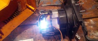
Varistor in the power supply
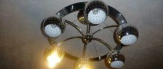
Craftsmen also use varistors when assembling their fakes from LED lamps. And special craftsmen manage to place them in sockets and plugs. You can think of a lot to protect your electronics if you have a problem with power surges in your home. The scope of their application is extensive. These can be installations with a voltage of 20 kV and with a voltage of 3V. This may be a network with alternating current, or it may be with direct current. Truly, varistors can be found almost everywhere.
So what characteristics does a varistor have?
As a rule, the following parameters are used to describe a varistor:
Varistor capacitance in closed state. During operation, its value may change. At particularly high current, it decreases to almost zero. Denoted as Co.
The maximum energy in Joules that a varistor can absorb in one pulse. Indicated by W. Maximum value of pulse current, at 8/20ms. Designated as Ipp. The root mean square value of the alternating voltage in the circuit. Denoted as Um. Limit voltage at direct current. Denoted as Um=. For approximate calculations of operating voltage, we recommend using an Un value of no more than 0.6 with alternating current and 0.8 with direct current.
In 220V networks, varistors with a minimum classification voltage (Un) from 380 to 430 V are used. We should not forget about the varistor capacity when selecting. As a rule, it depends on the size of the varistor. Thus, the varistor TVR 20 431 has a capacity of 900 pF, and TVR 05 431 - 80 pF. These values can always be found in the reference material.
In the diagrams, the varistor is designated as follows:
RU is the designation of the varistor itself. The number next to RU is the sequential number. That is, what number of varistors are they in the circuit? The letter U at the bottom left of the oblique passing through the varistor means that this element has the ability to change voltage. Also, the varistor markings are often indicated on the diagrams. We will talk about marking and its decoding below.
This is how a varistor is designated in diagrams
Main settings
To choose the right varistor, you need to know its main technical characteristics:
- The classification voltage may be designated as Un. This is the voltage at which a current of 1 mA begins to flow through the varistor; with further excess, the current increases like an avalanche. It is this parameter that is indicated in the marking of the varistor.
- Rated power dissipation P. Determines how much the element can dissipate while maintaining its characteristics.
- The maximum energy of a single pulse W. Measured in Joules.
- Maximum pulse current Ipp. Despite the fact that the front rises within 8 μs, and its total duration is 20 μs.
- Container in closed state - Co. Since in the closed state a varistor is like a capacitor, because its electrodes are separated by a non-conducting material, it has a certain capacitance. This is important when the device is used in high-frequency circuits.
Read also: Rules for laying cables underground
There are also two types of stress:
— maximum effective or root mean square variable;
- Um= — maximum constant.
Varistor protection of equipment
Varistor protection is used in household appliances. They can be soldered into the board itself, or brought out and secured with separate wires. Varistors must be connected in parallel. Connecting them in series simply does not make sense. In this case, current simply will not flow through the circuit.
How does varistor protection work?
For example, lightning struck near your house. Or she could have gotten caught in a power line. There is a power surge in the network. The varistor absorbs it and if the pulse is too strong/long, the varistor dies. That is, a varistor guarantees that your sensitive electronics will not burn out from a power surge. However, it should be remembered that the varistor can become a short circuit point during prolonged operation at maximum voltage.
Above we described several ways to avoid this. Use varistors with thermistors or include fuses in the circuit. To simplify everything as much as possible: at low voltage a varistor is a blocking device, at high voltage it is a conductive device.
AC transient waveform
Electric soldering iron with temperature control
Power: 60/80 W, temperature: 200'C-450'C, quality…
More details
Varistors are connected directly to the power supply circuits (phase-neutral, phase-phase) when operating on alternating current, or plus and minus power when operating on direct current and must be designed for the appropriate voltage. Varistors can also be used to stabilize DC voltage and mainly to protect the electronic circuit from high voltage surges.
Varistor selection
To effectively and reliably protect your equipment, you need to choose a varistor wisely. As a rule, to protect household appliances, varistors with a threshold voltage value from 275 to 430 V are used. We will not go into particular detail in the selection of varistors taking into account other values (capacitance, etc.). There are many nuances here that simply cannot be considered in the format of this article. For a more accurate selection of a varistor, we can recommend using reference books on varistors. They indicate all the characteristics that a particular varistor has. This will allow you to choose the most suitable one for your goals and objectives.
Another important parameter when choosing a varistor is the response speed. As a rule, for most varistors it is about 25 ns. But this is not always enough.
Then varistors with shorter response times are suitable for you. An unattainable ideal in terms of response speed are varistors manufactured using the SIOV-CN multilayer structure technology. Their response speed can be less than 1 ns.
Such varistors are necessary for protection against static electricity. In household appliances, such varistors are practically not used.
A varistor set to zero can serve as a guarantee of the life of your equipment during any power surges. Naturally, taking into account the fact that it is installed on the phase too.
Have you probably heard about cases when many people’s electronics burned out at once? This happens precisely due to the fact that only the phase goes through the wires. A varistor also protects against this.
Use in everyday life
The purpose of varistors is to protect the circuit during pulses and overvoltages on the line. This property allowed the elements in question to find their application as protection:
Most cheap power supplies do not install any protection. But in good models, varistors are installed at the input.
In addition, everyone knows that the computer must be connected to power through a special extension cord with a button - a surge protector. It not only filters interference, but varistors are also installed in normal filter circuits.
Electricians often recommend protecting Chinese LED lamps by installing a varistor parallel to the socket. They also protect other devices; some install a varistor in a socket or plug to protect the connected equipment.
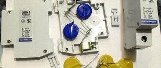
To protect the entire apartment, you can install a varistor on a DIN rail; in good devices, real powerful varistors with a diameter of a fist are located in the housing. An example of such a device is OIN-1, which is shown in the photo below:
In conclusion, I would like to note that the purpose of a varistor is to protect any electrical circuit. The operating principle is based on changing the resistance of the semiconductor structure under the influence of high voltage. The voltage at which a current of 1 mA begins to flow through the element is called classification. This and the diameter of the element are the main parameters when choosing. Perhaps we have clearly explained what a varistor is and what it is needed for, ask questions in the comments if something is not clear to you.
Finally, we recommend watching useful videos on the topic of the article:
You probably don't know:
Currently, varistors are manufactured by industry in accordance with GOST 13453-68, GOST 17598-72. The marking of varistors consists of letters and numbers.
first element —
letters
CH (nonlinear resistance),
the second element is
a number indicating the type of material used (1 – silicon carbide);
third element—
a number indicating the type of structure (1 – rod; 2 – disk);
fourth element -
number - rated voltage (in volts);
fifth Element—
number – permissible deviation from the rated voltage (in percent).
Application of varistors. Varistors are connected in parallel to the load, and when the input voltage surges, the main noise current flows through them, and not through the equipment. Thus, varistors dissipate interference energy in the form of heat. Just like a gas discharger, a varistor is a multiple-action element, but it restores its high resistance much faster after the voltage is removed.
The advantages of varistors compared to gas dischargers are:
§ Inertia-free monitoring of voltage drops;
§ wide range of operating voltages (from 12 to 1800 V);
§ long service life;
§ have a lower cost.
They are used in industrial equipment and household appliances:
§ to protect electronic devices: thyristors, transistors, diodes;
§ for electrostatic protection of radio equipment inputs;
§ for protection against electromagnetic surges in powerful inductive elements;
§ as a spark extinguishing element in electric motors and switches.
The typical response time of varistors when exposed to overvoltage is no more than 25 ns, but to protect some types of equipment it may not be enough (for electrostatic protection no more than 1 ns is needed). Therefore, the improvement of varistor manufacturing technology around the world is aimed at increasing their performance. For example, the company “S+M Epcos”, thanks to the use in the manufacture of varistors of the multilayer structure SIOV-CN and their SMD design (leadless design for surface mounting), is able to achieve a response time of less than 0.5 ns (when such elements are located on To obtain the specified speed, the printed circuit board already needs to minimize the inductance of the external connecting conductors). In the disk design of varistors, due to the inductance of the leads, the response time increases to several nanoseconds.
Short response time, high reliability, excellent peak electrical characteristics over a wide operating temperature range with small dimensions make multilayer varistors the first choice when choosing static charge protection elements.
For example, in the field of cell phone production, multilayer varistors can already be considered a standard in protection against static electricity. CN varistors can reliably protect against static discharges: keyboards, fax and modem connectors, charger connectors, inputs of integrated analog microcircuits, microprocessor outputs.
For application, the operating voltage of varistors is selected based on the permissible dissipation energy and the maximum permissible voltage amplitude. The limiting voltage is approximately equal to the qualification voltage (Un) of the varistor. For approximate calculations, it is recommended that at alternating voltage it does not exceed Uin
Read also: How to measure the diameter of a pipe with a caliper
For a network with an effective voltage of 220 V (50 Hz), varistors with a classification voltage of at least 380.430 V are usually installed. For a varistor with a classification voltage of 430 V, with a current pulse of 100 A, the voltage will be limited to about 600 V.
To increase power dissipation, varistors can be connected in series (or in parallel, if selected according to identical parameters). The sizes of varistors depend on the power, but since such elements operate under pulsed overload, they often indicate the dissipated energy in joules:
The maximum permissible energy dissipation value of the varistor used must exceed this value.
Since overheating of the varistor leads to its damage, such elements are also produced with unique properties, for example, having temperature protection - a breaking mechanical contact in the protected circuit, which significantly increases the reliability of the unit.
Its essence lies in the fact that domestic manufacturers produce components with technical parameters no worse than those produced abroad (however, it is much more difficult for a radio amateur to purchase them - imported ones can often be found on sale).
The main disadvantage of a varistor is its large intrinsic capacitance, which is introduced into the circuit. Depending on the design, type and voltage rating, this capacitance can range from 80 to 30,000 pF. However, for some applications, a large capacitance can be an advantage, for example, in a filter that combines the function of voltage limiting (for such applications, varistors with increased capacitance can be ordered). The second disadvantage is the lower maximum permissible power dissipation compared to arresters (to increase the dissipation power, manufacturers increase the size of the varistor housing).
Switching schemes. To protect equipment from impulse voltages of any kind, the use of varistors is recognized. Varistors are nonlinear resistors whose resistance varies depending on the applied voltage. They have a two-way, symmetrical current-voltage characteristic. Due to this, varistors make it possible to simply and effectively solve the problems of protecting various devices from pulse voltages. The operating principle of a varistor is simple. The varistor is connected in parallel to the protected equipment, i.e. During normal operation, it is exposed to the operating voltage of the protected device. In operating mode (in the absence of pulse voltages), the current through the varistor is negligible, and therefore the varistor under these conditions is an insulator. When a voltage pulse occurs, the varistor, due to the nonlinearity of its characteristics, sharply reduces its resistance to fractions of an Ohm and shunts the load, protecting it and dissipating the absorbed energy in the form of heat. In this case, a current reaching several thousand amperes can flow through the varistor for a short time. Since the varistor is practically inertia-free, after the voltage pulse is extinguished, it again acquires a very high resistance. Thus, connecting a varistor in parallel with electrical equipment does not affect its operation under normal conditions, but shunts interference pulses.
Photoresistor –
a semiconductor device whose conductivity changes when exposed to light.
The principle of operation of photoresistors is based on the phenomenon of photoconductivity of semiconductors. Photoconductivity is an increase in the electrical conductivity of a semiconductor under the influence of light. The reason for photoconductivity is an increase in the concentration of charge carriers - electrons in the conduction band and holes in the valence band. The light-sensitive layer of semiconductor material in such resistors is placed between two conductive electrodes. Under the influence of light flux, the electrical resistance of the layer changes several times (for some types of photoresistance it decreases by two to three orders of magnitude). Depending on the layer of semiconductor material used, photoresistors are divided into lead sulfide, cadmium sulfide, bismuth sulfide and polycrystalline selenium-cadmium. Photoresistors have high sensitivity, stability, they are economical and reliable in operation. In a number of cases, they successfully replace vacuum and gas-filled photocells.
Robot principle. When a photoresistor is illuminated, photon energy is spent on transferring electrons to the conduction band.
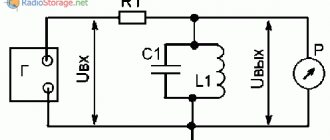
Rice. 2.12.. Connecting a photoresistor to a DC circuit
The number of free electron-hole pairs increases, the resistance of the photoresistor drops, and a light current flows through it, determined by the formula:
If a photoresistor is connected in series with a voltage source (Fig. 2.12.) and is not illuminated, then a dark current IT will flow in its circuit:
where E is the EMF of the power source; RT is the value of the electrical resistance of the photoresistor in the dark, called dark resistance; RH is the load resistance.
The difference between the light and dark current gives the value of the current 1ph, which is called the primary conduction photocurrent
When the radiant flux is small, the primary conduction photocurrent is practically inertia-free and varies in direct proportion to the magnitude of the radiant flux incident on the photoresistor. As the magnitude of the radiant flux increases, the number of conduction electrons increases. Moving inside a substance, electrons collide with atoms, ionize them and create an additional flow of electrical charges, called secondary conductivity photocurrent. An increase in the number of ionized atoms inhibits the movement of conduction electrons. As a result of this, changes in the photocurrent lag in time relative to changes in the light flux, which determines some inertia of the photoresistor.
Design. The basis of a photoresistor is a layer (or film) of semiconductor material on a substrate (or without it) with electrodes applied to it, through which the photoresistor is connected to an electrical circuit. The photoresist layer is obtained by pressing the powder or spraying a water-alcohol suspension of semiconductor material directly on the surface of the substrate, chemical deposition, epitaxy, or sputtering. The layers (films) obtained in this way can be annealed. Depending on the purpose, photoresistors can be single- and multi-element (mosaic), with or without cooling, open and sealed, made as separate units. products or as part of integrated circuits. To expand its function and capabilities, the photoresistor is supplemented with filters, lenses, rasters (optical modulators), preamplifiers (in microminiature version), thermostats, backlighting, cooling systems, etc.
Rice. 2.13. Cooled photoresistor: 1 – input window; 2 – photosensitive element; 3 – contact block; 4 – preamplifier; 5 – heat sink; 6 – electrical terminals; 7-base; 8 - thermistor; 9 – thermoelectric cooler .
Sulfides, selenides and tellurides of various elements, as well as AlMBv-type compounds, are widely used as materials for photoresistors. In the infrared region, photoresistors based on PbS, PbSe, PbTe, InSb can be used, in the region of visible light and the near ultraviolet spectrum - CdS.
Date added: 2015-06-12; ; ORDER A WORK WRITING
Advantages of using a varistor
A varistor is like a Kalashnikov assault rifle. Simple, reliable, cheap. And widespread everywhere. It will always work and will not let you down. The scope of its application is huge. As we wrote above, from 20 kV to 3V. Well, don’t forget about the response time. 25ns for an average varistor is quite good. And there are instances with a response speed below 0.5 ns.
But, like everything in this world, the varistor also has its drawbacks. These include low-frequency noise during operation, large varistor capacitance (from 70 to 3000 pF) and the tendency of varistor materials to become obsolete. The advantages of a varistor outweigh the disadvantages. That is why it has become so widespread. Just like the Kalashnikov assault rifle.
How to check a varistor?
Here are 3 methods available to almost everyone:
- Inspection
- Check the varistor with a multimeter
- Ring the chain.
Let's start with the simplest way - look at the varistor
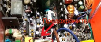
To access it, you will have to disassemble the household appliance and clean it of dust. Here you will need a screwdriver and a brush. Dust is the main problem with power supplies. A damaged varistor can be detected by cracks in the housing, swelling, and obvious signs of exposure to high temperatures. (At a minimum, a slightly melted body, at a maximum - traces of a short circuit).
The varistor is coated on the outside, usually with a ceramic or epoxy coating. When the varistor overheats, the coating cracks.
Multimeter
Testing a varistor with a multimeter is quite simple. We set the measurement limit on the multimeter. We turn it to the maximum, usually 2 megaohms (2MOhm, 2M, less often 2000K). When measuring, the multimeter should show a resistance closer to infinity. Often, it shows 1-2 megaohms.
Do not touch the varistor with your hands when measuring! In this case, the multimeter will show you the resistance of your body, not the varistor.
Ringing
When ringing, you will have to unsolder one of the varistor legs from the circuit. Calling should be done from different directions. The working varistor does not ring, which is understandable. No current flows through it. Resistance doesn't allow it.
Varistor marking
If your varistor is faulty, then knowing the varistor markings will be of great help to replace it. The marking itself is located on the case and is a set of Latin letters and numbers. Despite different manufacturers, for the most part, the markings on varistors are not very different and are quite easy to read.
As an example, here are 2 different varistors from different manufacturers:
- CNR-12D182K
- ZNR V12182U.
The first number 12 indicates the diameter of the varistor in millimeters. The second number is 182K opening voltage. 18 – voltage, 2 – coefficient. CNR is the designation of the varistor material. In this particular example, the varistor is made of metal oxides.
K – used to indicate the accuracy class. That is, if it is written on the varistor body - 275K, then K is the accuracy of 10%, and 275 is the opening voltage. And the opening voltage is calculated as follows - 275 + - 27.5. That is, for example, our 20D471K varistor can be replaced with a TVR20471 varistor. Or any other analogue of a varistor. For example – SAS471D20. You just need to know the basic principles of labeling.
True, this will not work with domestic varistors. You will have to use reference materials. Our varistors are designated as follows: CH2-1, VR-1 and CH2-2. For example: CH-2 – zinc oxide varistors. But this can only be found out from reference materials.
Despite the labeling principles described above, we strongly recommend using reference literature when choosing a varistor. It indicates all the necessary characteristics of the varistor, including those that cannot be recognized by the markings.