Low-power power supplies (up to several hundred watts) usually use single-phase rectifiers.
In powerful sources it is advisable to use three-phase rectifiers. Rectifiers have the following main parameters: a) average value of output voltage uout
Uav= 1/T· T∫0uoutdt
where T is the network voltage period (for an industrial network - 20 ms);
- average value of output current ioutx and Iav= 1/T· T∫0ioutdt
- output voltage ripple factor ε = Um/ Uav, where Um is the amplitude of the lowest (fundamental) harmonic of the output voltage. The ripple factor is often measured as a percentage.
Let's denote it by ε %: ε % = Um/Uav · 100%
These parameters are the most important when using a rectifier.
Rectifier parameters
When designing a rectifier, the following parameters are also widely used to characterize its internal features:
- effective value Uin of the rectifier input voltage;
- maximum reverse voltage Urev.max on a separate diode or thyristor (i.e. on the valve). This voltage is usually expressed through voltage Uav;
- average value Id.av of the current of an individual valve;
- maximum (amplitude) value Id.max of the current of an individual valve.
Currents Id.av and Id.max are usually expressed through Iav. The Urev.max value is used to select a valve based on voltage. Values
Id.sri Id.max are used to select a valve based on current. Here it should be borne in mind that due to the low thermal inertia of the semiconductor valve, it can fail even in the case when its average current Id.srm is small, but the maximum current Id.max is large.
Operating principle and diagrams
If single-phase or bridge single-phase rectifiers are used for low-power DC circuits, then three-phase rectifiers are sometimes needed to power more powerful loads. Three-phase rectifiers make it possible to obtain large values of direct currents with low levels of output voltage ripple, which reduces the requirements for the characteristics of the smoothing output filter. So, first, consider a single-cycle three-phase rectifier, shown in the figure below:
In the single-ended circuit shown in the figure, only three rectifier diodes are connected to the terminals of the secondary windings of a three-phase transformer. The load is connected to the circuit between the common point at which the cathodes of the diodes converge and the common terminal of the three secondary windings of the transformer. Let's now look at the timing diagrams of currents and voltages occurring in the secondary windings of the transformer and on one of the diodes of a three-phase single-ended rectifier:
Schematic diagram of the operation of a three-phase converter
Some DC devices require more supply voltage than the single-ended circuit above can provide. Therefore, in some cases, a three-phase push-pull rectifier circuit is more suitable. Its schematic diagram is shown in the figure below. As we have already noted, the filter requirements are decreasing, you can see this in the diagrams. This circuit is known as a three-phase Larionov bridge rectifier:
Now take a look at the diagrams and compare them with a single-ended circuit. The output voltage in a bridge circuit is easily represented as the sum of the voltages of two single-ended rectifiers operating in opposite phases. Voltage Ud = Ud1+Ud2. The number of output phases is obviously greater and the network ripple frequency is greater.
In this particular case, there are six phases of constant voltage instead of the three that were in the single-cycle circuit. This is why the requirements for the anti-aliasing filter are reduced, and in some cases it can be completely dispensed with.
Three phases of the windings, coupled with two half-cycles of rectification, give a main ripple frequency equal to six times the network frequency (6 * 50 = 300). This can be seen from the voltage and current diagrams. Bridge connection can be considered as a combination of two single-ended three-phase circuits with a zero point, with diodes 1, 3 and 5 being the cathode group of diodes, and diodes 2, 4 and 6 being the anode group. Two transformers seem to be combined into one. At each moment of current passing through the diodes, two diodes are simultaneously involved in the process - one from each group.
Interesting read: what are klystrons.
The cathode diode opens, to which a higher potential is applied relative to the anodes of the opposite group of diodes, and in the anode group exactly that diode opens, to which the potential is applied lower relative to the cathodes of the diodes of the cathode group.
It will be interesting➡ What is electric current, types and conditions of its existence
The transition of working time intervals between diodes occurs at moments of natural switching, the diodes work in order. As a result, the potential of common cathodes and common anodes can be measured by the upper and lower envelopes of the phase voltage graphs (see diagrams). The instantaneous values of the rectified voltages are equal to the potential difference between the cathode and anode groups of diodes, that is, the sum of the ordinates in the diagram between the envelopes.
The rectified current of the secondary windings is shown in the diagram for a resistive load. In the same way, you can get more than six phases of constant voltage from a three-phase transformer: nine, twelve, eighteen and even more. The more phases (the more pairs of diodes) in the rectifier, the lower the level of output voltage ripple.
Rectifier with regulator
Bridge device type
A three-phase bridge rectification circuit uses six diodes (or thyristors if control is required). The output voltage is characterized by three values: minimum U, average U and peak voltage. A full-wave three-phase rectifier is similar to a Heitz bridge. Diagram of a full-wave three-phase device. A conventional three-phase rectifier does not use a neutral. For 230 V / 400 V network between two rectifier inputs. Indeed, there is always a composite voltage U (= 400 V) between the 2 inputs. An uncontrolled device means that the average output U cannot be adjusted for that input U. Uncontrolled rectification uses diodes.
Three-phase diode rectifier
A controlled rectifier allows you to regulate the average output voltage by influencing the response delay of the thyristor (used instead of diodes). This command requires complex electronic circuitry.
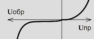
The diode behaves like a thyristor loaded without delay. Output U three-phase output voltage. There are 7 curves in total: 6 sinusoids and a red curve connecting the upper part of the sinusoids (“sinusoidal caps”). 6 sinusoids represent 3 voltages that make up U between phases and 3 identical voltages, but with opposite sign:
U31 = -U13U23 = -U32U21 = -U12.
The red curve represents U at the output of the rectifier, that is, at the terminals of the resistive load. This U does not refer to neutral. She swims. This U fluctuates between 1.5 Vmax and 1.732 Vmax (root of 3). Umax is the peak value of one voltage and is 230 × 1.414 = 325 V.
Properties of three-phase voltage
A curve acting only on a resistive load, uncontrolled rectification (with diodes), does not return to zero, unlike a monofrequency device (Graetz bridge). Thus, the ripple is much lower and the dimensions of the inductor and/or smoothing capacitor are less restrictive than for a Heitz bridge. At least two phases are required to obtain a non-zero output U. Minimum, maximum and average voltage value. Numerically, for a 230 V / 400 V network, the rectified voltage fluctuates between a minimum voltage: 1.5 V min = 1.5 x (1.414×230) = 488 V, and a maximum: 1.732 Vmax = 1.732 x (1.414×230) = 563 IN.
Average value of three-phase rectified voltage: avg = 1.654Vmax = 1.654 x (1.414×230) = 538 V. Output voltage of three-phase output rectifier (zoom). 3-phase full wave rectifier MDS 130A 400V. 5 terminals: 3 phases, + and -. This rectifier contains 6 diodes. Thus, the following points can be summarized:
- 6 diodes, 2 diodes per phase - weak ripple compared to a single-wave rectifier (Heetz bridge);
- average value of rectified voltage: 538 V for a network of 230 V / 400 V;
- the neutral is not used by the three-phase rectifier.
Interesting read! What is a varistor and where is it used?
Diode bridge operation
It consists of four diodes and this configuration is connected across the load. During the positive half cycle of the input signals, diodes D1 and D2 are forward biased and D3 and D4 are reverse biased. When a voltage greater than the threshold level of diodes D1 and D2 begins to conduct, current begins to flow through it, as shown in the figure below on the red line. During the negative half cycle of the AC input signal, diodes D3 and D4 are forward biased and D1 and D2 are reverse biased. Load current starts flowing through diodes D3 and D4 when these diodes start conducting as shown in the figure.
It will be interesting➡ Kirchhoff's laws in simple words: definition for an electrical circuit
In both cases, the direction of the load current is the same, as shown in the figure one way, which means DC. Thus, by using a bridge rectifier, the input current AC is converted to DC. The output to the load using this bridge rectifier is pulsating in nature, but to obtain pure DC, an additional filter such as a capacitor is required. The same operation is applicable for various bridge rectifiers, but in case of controlled rectifiers, the thyristor is triggered to control the current to the load.
Mode 1 (from α to π). In the positive half-cycle of the applied AC signal SC1, T1 and T2 are forward biased and can be turned on at an angle α. The load voltage is equal to the positive instantaneous AC supply voltage.
Mode 2 (π toπ + α). At wt = π the input power is zero, and after π it becomes negative. But inductance counteracts any changes to maintain the DC load and in the same direction.
Operation diagram of a three-phase rectifier
Three-phase rectifier circuit with zero terminal
Its timing diagrams are shown in Fig. 2.76.
The ripple factor of the rectified voltage is 0.25, while for a full-wave single-phase rectifier the ripple factor is 0.67. The ripple frequency in a three-phase rectifier is three times higher than the frequency of the supply network.
Action of the scheme
The operation of a 3-phase fully controlled bridge rectifier circuit is described in this page. A three-phase fully controlled bridge rectifier can be constructed using six thyristors. It can be seen that phase A voltage is the highest of the three phase voltages when Θ is between 30° and 150°.
It can also be seen that phase B voltage is the highest of the three-phase voltages when Θ is between 150 and 270° and that phase C voltage is the highest of the phase voltages when Θ is between 270 and 390° or 30° in the next cycle.
Phase A voltage is the lowest of three-phase voltages when Θ is between 210 and 330°. It can also be seen that phase B voltage is the lowest of the phase voltages when Θ is between 330 and 450° or 90° in the next cycle, and that phase C voltage is lowest when Θ is between 90 and 210°.
If diodes are used, diode d1 instead of s1 would conduct from 30 to 150°, diode d3 would conduct from 150 to 270° and diode d5 from 270 to 390° or 30° in the next cycle. In the same way, diode d4 would conduct from 210 to 30°, diode d6 from 330 to 450° or 90° in the next cycle, and diode d2 would conduct from 90 to 210°. The positive output voltage rail of the bridge connects to the highest segments of the three-phase voltage envelope and the negative output voltage rail to the lowest segments of the envelope.
At any time other than transient periods, when electric current is moved from one diode to another, only one of the following pairs is operating at any one time.
| Interval Θ | Working diode |
| 30 to 90 | D1 and D6 |
| 90 to 150 | D1 and D2 |
| 150 to 210 | D2 and D3 |
| 210 to 270 | D3 and D4 |
| 270 to 330 | D4 and D5 |
| 330 to 360 and 0 to 30 | D5 and D6 |
It will be interesting➡ What is a Faraday cage
If thyristors are used, their activation can be delayed by selecting the desired firing angle. When the thyristors are turned on at angle 0, the output from the bridge rectifier is the same as from the diode circuit. For example, it is clear that d1 begins to conduct only after Θ = 30°. Indeed, it can only begin to conduct after Θ = 30°, as it is reversed up to Θ = 30°. The bias across d1 becomes 0 when Θ = 30° and diode d1 starts to become forward-directional only after Θ = 30°.
When Va(Θ)= E*sin (Θ), diode d1 is reverse directed before Θ = 30° and forward directed when Θ = 30°. At zero opening angle of the thyristors, s1 opens when Θ = 30°. This means that if a clock signal is needed to turn on s1, then the signal voltage Va(Θ) lags by 30° and if the firing angle is Θ, the thyristor s1 is fired when Θ = α + 30°. Provide that conduction is continuous, the following table represents a pair of thyristors in conduction at any instant.
| Interval Θ | Working diode |
| α + 30 to α + 90 | S1 and S6 |
| α + 90 to α + 150 | S1 and S2 |
| α + 150 to α + 210 | S2 and S3 |
| α + 210 to α + 270 | S3 and S4 |
| α + 270 to α + 330 | S4 and S5 |
| α+330 to α+360 and α+0 to α+30 | S5 and S6 |
The operation of a bridge rectifier is illustrated using the applet that follows this paragraph. You can set the opening angle within 0° < opening angle < 180° and you can also set the instantaneous angle.
The applet shows a pair of thyristors in a conducting state at a selected moment. The path of electric current is shown in red on the diagram. The instantaneous angle can be typed into its text field, or changed by moving the scroll line button. The rotating phasor diagram is quite useful to illustrate how the circuit works. Once the opening angle is set, the vector position for the opening angle is set.
Three-phase high power rectifier
Then, with a change in instantaneous angle, the conducting pair connects to the thick orange arcs. (in the picture) One way to imagine is to imagine two brushes that are 120° wide and a device in phase coupled to the behavior of the brushes.
The brush that has the “opening angle” written next to it acts as a brush connected to the positive rail and the other acts as if it is connected to the negative rail. This diagram illustrates how a rectifier circuit acts as a commutator and converts alternating current to direct current. The output voltage is determined by the amplitude of the phase voltage, being a single value.